LEAB RBC 1280 User manual

www.leab.eu
USER MANUAL
VERSION 3
22/06/2021
CHARGER
RBC IP66
LEAB Automotive GmbH Thorshammer 6 24866 Busdorf

Table of Contents
1 About this Manual................................................................................................................ 3
2 Safety......................................................................................................................................... 4
2.1 Intended Use............................................................................................................... 4
2.2 Foreseeable Misuse.................................................................................................. 5
3 About this Product............................................................................................................... 6
4 Technical Specifications.................................................................................................... 8
5 Package Contents................................................................................................................. 9
6 Assembly.................................................................................................................................. 9
7 Setting the Charging Parameters................................................................................... 9
8 Checking the Charging Parameter Settings............................................................... 12
9 Changing charging parameters....................................................................................... 13
10 Installation.............................................................................................................................. 13
11 Operation................................................................................................................................. 16
11.1 Switching On ............................................................................................................... 16
11.2 Switching Off............................................................................................................... 17
12 Maintenance........................................................................................................................... 18
13 Disposal.................................................................................................................................... 18
14 EU Declaration of Conformity.......................................................................................... 18
15 Appendix .................................................................................................................................. 18
Table of Contents LEAB Automotive GmbH

1 About this Manual
Read this manual carefully and keep it in a safe place. This manual is aimed at
Users with prior knowledge of automotive electrics.
Any modifications to the product or its components are prohibited and do not
conform to its intended use. Only use original LEAB or LEAB-approved ac-
cessories.
Throughout the manual, you will be alerted to warnings and safety notices
about potential hazards associated with handling the device. The colours and
signal words indicate the severity of the hazard:
Notice
Possibility of material damage
The signal word
Attention
indicates that there is a possibility of
material damage. To avoid material damage, follow the
instruction.
CAUTION
Danger that can lead to minor injuries
Safety instructions with the signal word
CAUTION
indicate a
hazard which, if not avoided, can result in minor or moderate
injury. Read the safety instructions carefully and follow them to
avoid the hazard.
WARNING
Hazards that can lead to severe injuries or death
Safety instructions with the signal word
WARNING
indicate a
hazard which, if not avoided, can result in death or severe injury.
Read the safety instructions carefully and follow them to avoid
the hazard.
3LEAB Automotive GmbH Thorshammer 6 24866 Busdorf
LEAB Automotive GmbH 1 About this Manual
DANGER
Danger that will lead to severe injury or death
Safety instructions with the signal word
Danger
indicate a hazard
which, if not avoided, will result in death or severe injury. Read
the safety instructions carefully and follow them to avoid the
hazard.
You will find useful tips and tricks in certain parts of the manual. These ap-
pear as follows:
TIP
Tips provides additional, useful information.
Read the tip carefully and follow the instructions where
applicable.
2 Safety
This manual will help you to handle the device safely. Use the device solely in
accordance with its intended use. Any modifications to the device or its com-
ponents are prohibited and do not conform to its intended use. Observe the
safety instructions.
Keep this manual is a place where it can be accessed quickly.
2.1 Intended Use
The charger is a robust charger for permanent installation in vehicles, with 12
and 24 V on-board power supply, for charging lead batteries and LION Brix
lithium batteries.
The device is designed for a temperature range of -35 °C ... 55 °C. Do not
charge batteries with this charger outside the specified temperature range. At
higher temperatures, the output power of the charger automatically de-
creases.
4 LEAB Automotive GmbH Thorshammer 6 24866 Busdorf
2 Safety LEAB Automotive GmbH
WARNING
Risk of fire from overheated battery
Flammable gases can escape if the battery overheats.
1. Always charge batteries in well-ventilated rooms and away
from ignition sources.
WARNING
Burns from escaping acid
Acid can leak out when handling batteries.
1. Wear acid-proof clothing when handling batteries.
WARNING
Risk of injury from damaged, frozen or deformed batteries
Damaged, frozen or deformed batteries can cause injuries.
1. Before using the battery, make sure that the battery is un-
damaged and the electrolyte is not frozen.
2.2 Foreseeable Misuse
The charger is designed for Interior use in vehicles. Never assemble the char-
ger outside the vehicle. The charger is designed to charge all types of Lead-
acid batteries (wet, gel, AGM) and lithium batteries. Charge only the specified
battery types with the charger.
To avoid damage, never pinch the leads of the charger. In the event of dam-
age, unplug the charger immediately and contact your dealer or LEAB.
Notice
Device defects from incorrect installation
Incorrect installation can result in device defects.
1. Install the device in a dry and cool location.
5LEAB Automotive GmbH Thorshammer 6 24866 Busdorf
LEAB Automotive GmbH 2 Safety
3 About this Product
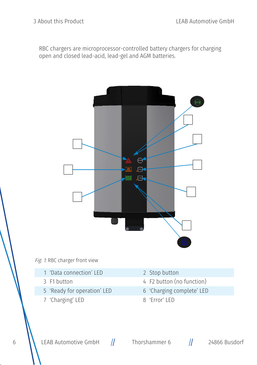
RBC chargers are microprocessor-controlled battery chargers for charging
open and closed lead-acid, lead-gel and AGM batteries.
2
3
4
5
6
7
8
1
Fig.1:
RBC charger front view
1 'Data connection’ LED 2 Stop button
3 F1 button 4 F2 button (no function)
5 'Ready for operation’ LED 6 'Charging complete’ LED
7 'Charging’ LED 8 'Error‘ LED
6 LEAB Automotive GmbH Thorshammer 6 24866 Busdorf
3 About this Product LEAB Automotive GmbH

1 2 3 4 5
Fig.2:
RBC charger connection side
1 Mains connection cable of the
charger 2 Charging cable, red
3 Charging cable, blue 4 Battery data line
5 Mounting bracket
7LEAB Automotive GmbH Thorshammer 6 24866 Busdorf
LEAB Automotive GmbH 3 About this Product
4 Technical Specifications
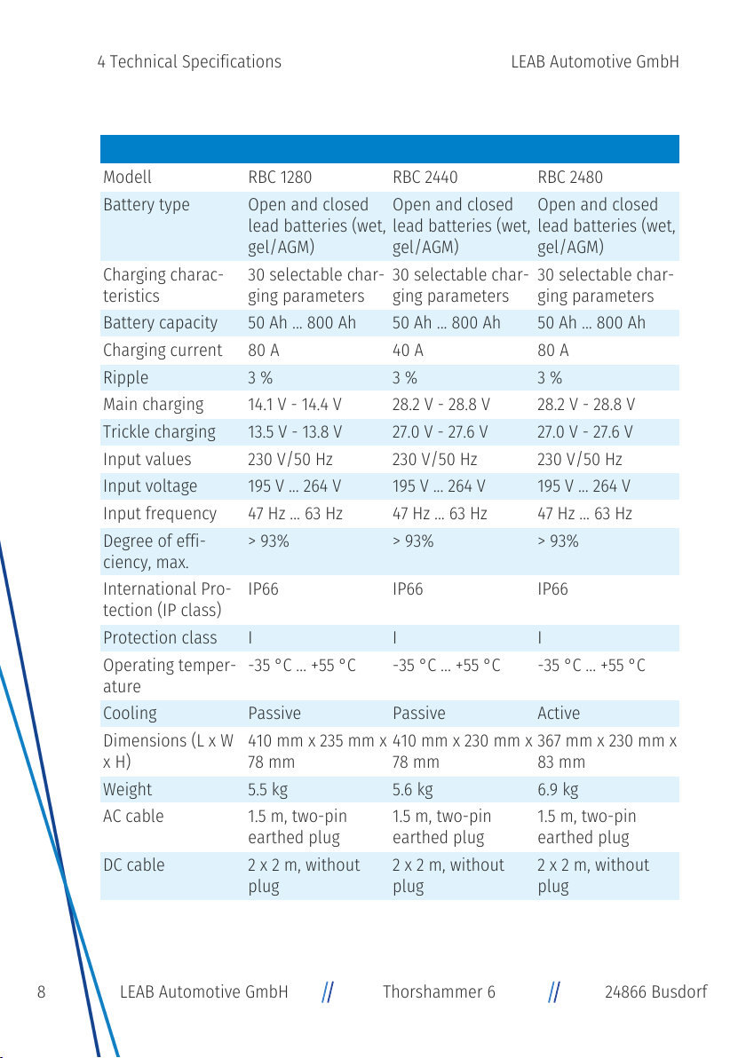
0101036982 0101036991 0101078270
Modell RBC 1280 RBC 2440 RBC 2480
Battery type Open and closed
lead batteries (wet,
gel/AGM)
Open and closed
lead batteries (wet,
gel/AGM)
Open and closed
lead batteries (wet,
gel/AGM)
Charging charac-
teristics 30 selectable char-
ging parameters 30 selectable char-
ging parameters 30 selectable char-
ging parameters
Battery capacity 50 Ah ... 800Ah 50 Ah ... 800Ah 50 Ah ... 800Ah
Charging current 80 A 40 A 80 A
Ripple 3 % 3 % 3 %
Main charging 14.1 V - 14.4 V 28.2 V - 28.8 V 28.2 V - 28.8 V
Trickle charging 13.5 V - 13.8 V 27.0 V - 27.6 V 27.0 V - 27.6 V
Input values 230 V/50 Hz 230 V/50 Hz 230 V/50 Hz
Input voltage 195 V ... 264 V 195 V ... 264 V 195 V ... 264 V
Input frequency 47 Hz ... 63 Hz 47 Hz ... 63 Hz 47 Hz ... 63 Hz
Degree of effi-
ciency, max. > 93% > 93% > 93%
International Pro-
tection (IP class) IP66 IP66 IP66
Protection class I I I
Operating temper-
ature -35 °C ... +55 °C -35 °C ... +55 °C -35 °C ... +55 °C
Cooling Passive Passive Active
Dimensions (L x W
x H) 410 mm x 235 mm x
78 mm 410 mm x 230 mm x
78 mm 367 mm x 230 mm x
83 mm
Weight 5.5 kg 5.6 kg 6.9 kg
AC cable 1.5 m, two-pin
earthed plug 1.5 m, two-pin
earthed plug 1.5 m, two-pin
earthed plug
DC cable 2 x 2 m, without
plug 2 x 2 m, without
plug 2 x 2 m, without
plug
8 LEAB Automotive GmbH Thorshammer 6 24866 Busdorf
4 Technical Specifications LEAB Automotive GmbH

5 Package Contents
Item No.
Battery charger 1x
Mounting plate 1x
User manual 1x
6 Assembly
To assemble the device, proceed as follows:
üChoose a cool, dry and well-ventilated assembly site.
üDo not mount the device directly next to or above batteries.
üGuarantee adequate cooling for an unimpeded supply of cooling air.
1. Mount the assembly plate with the side holes (5 mm Ø) on a flat surface.
2. Slide the device into the mounting rails of the assembly plate.
ðThe device is assembled.
7 Setting the Charging Parameters
The RBC charger contains 30 different charging parameters (charging charac-
teristic, battery capacity and charging mode) which you can select before con-
necting to the battery. A graphical illustration of the charging characteristics
can be found in
Appendix [
}
18]
.
To set the charging parameters, proceed as follows:
üBefore setting, select the desired settings using the table below.
üThe charger is disconnected from the 230 V mains.
üThe charger is not connected to the battery.
1. Connect the mains plug to a 230 V mains supply.
2. As soon as the 'Ready for operation' LED lights up blue (after approx. 5 s),
press the STOP button for 10 s until all LEDs are flashing briefly.
ðYou are in configuration mode.
NOTE!When first used, charging parameters 1 (charging characteristic
LK10-06) and 9 (battery capacity 50 Ah) are preset by default.
9LEAB Automotive GmbH Thorshammer 6 24866 Busdorf
LEAB Automotive GmbH 7 Setting the Charging Parameters

3. To select a parameter from the list, keep pressing the STOP button until you
reach the desired position.
Fig.3: F1 and F2
buttons
4. Select or deselect a setting by pressing the F1 button.
5. Remove the device from the 230 V mains.
ðThe charging parameters are set and saved.
Set the following parameters for the different 'Power
Supply’ charging modes:
NOTE!Depending on the charger, a voltage of 12 V or 24
V is permanently output as standard in the 'Power Sup-
ply' charging modes. If you require a higher voltage,
please contact LEAB directly.
Charging mode Settings
Charging mode (default) 25, Charging mode: OFF
27, CAN mode: OFF
30: Charging mode: OFF
PDO Power Supply 25, Charging mode: OFF
27, CAN mode: ON
30: Charging mode: OFF
SDO Power Supply 25, Charging mode: ON
27, CAN mode: ON
30: Charging mode: OFF
10 LEAB Automotive GmbH Thorshammer 6 24866 Busdorf
7 Setting the Charging Parameters LEAB Automotive GmbH
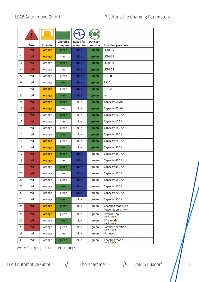
Fig.4:
Charging parameter settings
11LEAB Automotive GmbH Thorshammer 6 24866 Busdorf
LEAB Automotive GmbH 7 Setting the Charging Parameters
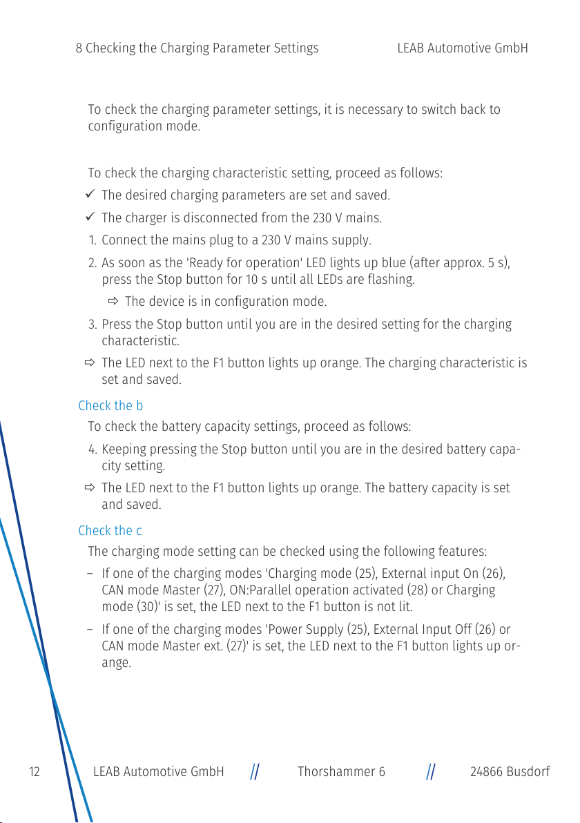
8 Checking the Charging Parameter Settings
To check the charging parameter settings, it is necessary to switch back to
configuration mode.
Check the Charging Characteristic Setting
To check the charging characteristic setting, proceed as follows:
üThe desired charging parameters are set and saved.
üThe charger is disconnected from the 230 V mains.
1. Connect the mains plug to a 230 V mains supply.
2. As soon as the 'Ready for operation' LED lights up blue (after approx. 5 s),
press the Stop button for 10 s until all LEDs are flashing.
ðThe device is in configuration mode.
3. Press the Stop button until you are in the desired setting for the charging
characteristic.
ðThe LED next to the F1 button lights up orange. The charging characteristic is
set and saved.
Check the battery capacity setting
To check the battery capacity settings, proceed as follows:
4. Keeping pressing the Stop button until you are in the desired battery capa-
city setting.
ðThe LED next to the F1 button lights up orange. The battery capacity is set
and saved.
Check the charging mode setting
The charging mode setting can be checked using the following features:
– If one of the charging modes 'Charging mode (25), External input On (26),
CAN mode Master (27), ON:Parallel operation activated (28) or Charging
mode (30)' is set, the LED next to the F1 button is not lit.
– If one of the charging modes 'Power Supply (25), External Input Off (26) or
CAN mode Master ext. (27)' is set, the LED next to the F1 button lights up or-
ange.
12 LEAB Automotive GmbH Thorshammer 6 24866 Busdorf
8 Checking the Charging Parameter Settings LEAB Automotive GmbH

9 Changing charging parameters
The settings of the charging parameters can be changed at any time. To do
this, proceed as follows:
üThe device is disconnected from the 230 V mains supply.
üThe device is not connected to a battery.
1. Connect the mains plug to a 230 V mains supply.
2. As soon as the 'Ready for operation' LED lights up blue (after approx. 5 s),
press the Stop button for 10 s until all LEDs are flashing.
ðThe device is in configuration mode.
3. Set the desired charging parameters as described in
Setting the Charging
Parameters [
}
9]
.
ðThe charging parameters are changed.
10 Installation
Battery Connection
To install the device in the vehicle, proceed as follows:
1. Disconnect the battery from the on-board power supply.
WARNING!Disconnect the negative cable first.
2. Secure the positive cable of the device as close as possible to the vehicle
battery with a suitable fuse.
3. Connect the positive cable of the device to the positive terminal of the bat-
tery.
4. Connect the negative cable of the device to the negative terminal of the
battery.
5. Connect the vehicle battery to the on-board power supply.
ðThe device is installed.
13LEAB Automotive GmbH Thorshammer 6 24866 Busdorf
LEAB Automotive GmbH 10 Installation

Connection to the 230 V Mains
To install the device to the 230 V mains, proceed as follows:
NOTE!The charger is only suitable for connection to fused, earthed 230 V
mains supplies.
1. Connect the mains plug to a 230 V mains supply.
ðThe charger is connected to the 230 V mains supply.
Connecting the Sensor Cable
The sensor cable measures the battery temperature (sensor cable TS) or the
battery temperature and voltage (sensor cable CTS) in order to charge the bat-
tery optimally.
To connect the sensor cable, proceed as follows:
NOTE!When connecting, pay attention to the instructions and notes in the
sensor cable installation instructions.
1. Connect the sensor cable to the charger.
ðThe sensor cable is connected.
Connecting the D-Sub Connector
The integrated D-Sub connector allows you to control various signals.
Pin Description
1 CAN Bus high*
2 Voltage sensor (+)
3 Temperature sensor (+)
4 LED green (+)
5 LEB yellow (+)
7 Insulated ground*
8 Pilot Brix
9 CBL relay contact, normally closed
10 CAN bus low*
11 Remote input (-)*
12 Temperature sensor (-)
14 LEAB Automotive GmbH Thorshammer 6 24866 Busdorf
10 Installation LEAB Automotive GmbH

Pin Description
14 LED red (-)
18 CBL relay contact, normally open
19 Remote input (+)*
20 Voltage sensor (-)
22 LED (-)
25 Insulated 5 V (50 mA) output (+)*
26 CBL input
*The CAN bus signals, CBL, the remote input and the insulated 5 V output are
galvanically isolated from the DC output.
NOTE!Pins that are not listed are not assigned.
External LED Connection
The LED shows the charge status of the battery.
To connect the external LEDs, proceed as follows:
1. Connect the wire ends of the external LEDs to pin 4, pin 5, pin 14 and pin 22.
ðThe external LEDs are connected.
EBrix Connection (24 V)
You can connect the RBC 24 V charger to the eBrix system using a suitable ad-
apter.
CBL Control Relay Connection
A potential-free changeover contact is integrated in the RBC chargers, which
switches during charging operation. This option can be used, for example, to
implement an electrical start interlock with 230 V connection or charge monit-
oring.
15LEAB Automotive GmbH Thorshammer 6 24866 Busdorf
LEAB Automotive GmbH 10 Installation

Switching Function of the Changeover Contact
Fig.5: Switching
Function of the
Changeover Contact
– When the charger is switched off, pin 9 and pin 26 are
connected.
– When the charger is switched on, pin 26 and pin 18 are
connected.
Technical Data (insulation) Capacity (max.values)
Output to hous-
ing: 500V Max. 60 V (DC): 0.25A
Output to ground 120V
To install the CBL control relay, proceed as follows:
1. Solder the end of the cable to the D-sub connector.
2. Connect the wire ends to pin 26, pin 9 and pin 18.
3. Plug the D-sub connector into the connector for the
CBL control relay on the device.
ðThe CBL control relay is installed.
11 Operation
11.1 Switching On
To switch on the device, proceed as follows:
1. Connect the mains plug to a 230 V mains supply.
ðThe device is switched on.
NOTE!After connection to the mains, the LED flashes red for 2 seconds
(device test).
NOTE!When the battery is charging, the 'Charging' LED is lit orange.
NOTE!When the battery is fully charged, the 'Charging complete' LED is lit
green.
16 LEAB Automotive GmbH Thorshammer 6 24866 Busdorf
11 Operation LEAB Automotive GmbH
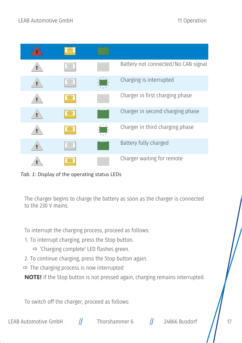
Operating status
Description
Battery not connected/No CAN signal
Charging is interrupted
Charger in first charging phase
Charger in second charging phase
Charger in third charging phase
Battery fully charged
Charger waiting for remote
Tab.1: Display of the operating status LEDs
Charging the Battery
The charger begins to charge the battery as soon as the charger is connected
to the 230 V mains.
Interrupting the Charging Process
To interrupt the charging process, proceed as follows:
1. To interrupt charging, press the Stop button.
ð‘Charging complete' LED flashes green.
2. To continue charging, press the Stop button again.
ðThe charging process is now interrupted
NOTE!If the Stop button is not pressed again, charging remains interrupted.
11.2 Switching Off
To switch off the charger, proceed as follows:
17LEAB Automotive GmbH Thorshammer 6 24866 Busdorf
LEAB Automotive GmbH 11 Operation

1. Disconnect the mains plug from the 230 V mains.
ðThe device is switched off.
12 Maintenance
Check the charger as follows every time before you use it:
– Check the mains cable and mains plug for damage.
– Check charging cables and connections for damage.
– Check the charger for external damage.
– Ensure that the wiring between the charging cable and the charger is se-
cure.
NOTE!For battery maintenance, refer to the battery manufacturer’s instruc-
tions.
13 Disposal
Dispose of the device in accordance with the Waste Elec-
trical and Electronic Equipment Regulations (WEEE).
The system must not be disposed of with household
waste. Take it to a recycling point or return it to your
point of sale.
14 EU Declaration of Conformity
The RBC charger complies with the requirements of the
following directives:
– 2014/30/EU: EMV
– 2014/35/EU: NRL
– 2011/65/EU: RoHS
15 Appendix
Charging Characteristics
NOTE!To select the correct charging characteristic for your battery, refer to
the instructions of your battery manufacturer.
18 LEAB Automotive GmbH Thorshammer 6 24866 Busdorf
15 Appendix LEAB Automotive GmbH
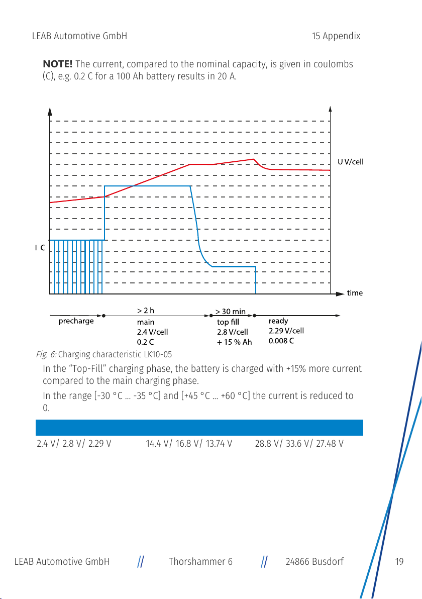
NOTE!The current, compared to the nominal capacity, is given in coulombs
(C), e.g. 0.2 C for a 100 Ah battery results in 20 A.
LK10-05 - Freely ventilated lead-acid
Fig.6:
Charging characteristic LK10-05
In the “Top-Fill” charging phase, the battery is charged with +15% more current
compared to the main charging phase.
In the range [-30 °C ... -35 °C] and [+45 °C ... +60 °C] the current is reduced to
0.
Voltage per cell 12 V system 24 V system
2.4 V/ 2.8 V/ 2.29 V 14.4 V/ 16.8 V/ 13.74 V 28.8 V/ 33.6 V/ 27.48 V
19LEAB Automotive GmbH Thorshammer 6 24866 Busdorf
LEAB Automotive GmbH 15 Appendix

LK10-06 - Freely ventilated lead-acid (default)
Fig.7:
Charging characteristic LK10-06
In the “Top-Fill” charging phase, the battery is charged with +15% more current
compared to the main charging phase.
In the range [-30 °C ... -35 °C] and [+45 °C ... +60 °C] the current is reduced to
0.
In the maintenance phase, the battery voltage is checked periodically; if the
battery voltage falls below 2.17 V per cell, the battery is charged for 2 minutes
with a pulse charge of 0.05 C.
Voltage per cell 12 V system 24 V system
2.4 V/2.8 V/Off 14.4 V/16.8 V/Off 28.8 V/33.6 V/Off
20 LEAB Automotive GmbH Thorshammer 6 24866 Busdorf
15 Appendix LEAB Automotive GmbH
Other manuals for RBC 1280
1
This manual suits for next models
5
Table of contents
Other LEAB Batteries Charger manuals

LEAB
LEAB Champ User manual

LEAB
LEAB 12100 User manual

LEAB
LEAB Champ 1207 User manual

LEAB
LEAB Clayton Power G3 Combi 1012-50 User manual

LEAB
LEAB CHAMP 12 V User manual

LEAB
LEAB TS 24/12-06 User manual

LEAB
LEAB ABC SCHUTZKLASSE II User manual

LEAB
LEAB 600W Series User manual

LEAB
LEAB CPC 1260 User manual

LEAB
LEAB CHAMP PRO 24 V User manual


