Leading Edge ALL-IN-ONE User manual

LIT ID: 406-01
Complete Perimeter Fall Protection System
ALL-IN-ONE
™
PATENT # US 8,448,923
*WARNING*
Serious injury or death may result if this product is used for purposes other than designed. The manufacturer provides the following instruc-
tions for the use and care of this equipment. It is the responsibility of the purchaser to understand and convey explicit instruction to each user.
The AES Manufacturing/Leading Edge Safety All-In-One™ complies with the requirements of the Federal Occupational Safety and Health
Administration (OSHA) when set up and used according to the manufacturers’ instructions.

ALL-IN-ONE™INSTRUCTION MANUAL
1
LEADING EDGE SAFETY, LLC
All-In-One Instruction Manual
Published by Leading Edge Safety, LLC,
North Kansas City, MO
ALL-IN-ONE COMPLETE FALL PROTECTION SYSTEM
is a registered trademark of
Leading Edge Safety, LLC
1345 Taney St
North Kansas City, MO 64116
www.LeadingEdgeSafety.net
Copyright © 2020 by Leading Edge Safety, LLC
PRINTED IN THE UNITED STATES OF AMERICA
E
N
G
L
I
S
H

ALL-IN-ONE™INSTRUCTION MANUAL
2
DIAGRAM OF PARTS
The All-In-One™ System is comprised of numerous parts. Below is a diagram of all the parts and names, in a parapet clamp
mounng conguraon.
E
N
G
L
I
S
H
Top parapet clamp storage
opening
Lumber rail bracket
Metal sliding bracket
w/ droplock pin
Gravelstop
groove
Adjustable clamp
Boom concrete
slab clamp
opening
Flat edge horizontal
mounng plate
Flat edge vercal
mounng plate
Bracket adjuster
Knob (not shown)
Adjustable parapet clamp

ALL-IN-ONE™INSTRUCTION MANUAL
3
1.0 Assembly/Setup
1.1 The rst step in assembling the All-In-OneTM system is determining the layout of the roof to be protected. Access points
and the need for a ladder access system should be examined. Further, any objects that will interfere with the railing
system should be evaluated, and may have to be protected with alternave systems, such as a warning line system for
intrusions into the railing system design.
1.2 The length of the fasteners used to aach the bases will depend on the structural integrity of the roof system. (Unless
the oponal parapet clamps are used, in which case no fasteners are needed.) A competent professional should make
the determinaon as to whether or not the length of fastener selected will be sucient to provide the proper safety
margin. If the oponal parapet clamps are used, a competent professional will need to determine if the parapet has
sucient strength to provide the proper safety margin. OSHA regulaons require that the system be able to withstand
a force of 200 pounds applied in an outward or downward direcon at any point along the railing system. For more
informaon, refer to OSHA regulaon 1926.502 “Guardrail Systems”.
1.3 Determine the rst corner from which work will begin. The bases which comprise the corner secon should be located
no less than 18.5 (eighteen) inches from the actual corner, and no more than 27 (twenty seven) inches from the same
corner.
2.0 Flat Edge and Gravel Stop Conguraon
Wood Applicaons: Four to six #14 coarse thread wood screws with 1.5" penetraon per screw in each All-In-One
Base into a solid wood base that is either an integral part of the structure or securely aached to the structure.
Wood Surface Applicaon
Concrete Low-Edge Applicaons: Four to six #14 coarse thread concrete anchors with 1.5" penetraon per screw in
each All-In-One Base into a solid concrete base.
Metal Deck Applicaons: Six #14 ne thread metal deck anchors in each All-In-One Base into metal deck securely
fastened to the structure.
Gravel Stops: Place the base so that the raised area between the horizontal mounng plate and base sits over the
gravel stop, and then secure the base just like you would in a at edge scenario.
E
N
G
L
I
S
H
Minimum 4 fasteners

ALL-IN-ONE™INSTRUCTION MANUAL
4
All tesng for the All-In-One was done with the above fastener conguraons to meet or exceed the OSHA
requirements per 1926.502 for guardrails. All tests were done with fasteners in the All-In-One base roof / oor
surface.
3.0 Parapet Walls
If the oponal parapet clamps are ulized, the system may be aached without fasteners, provided the parapet itself is
of sucient strength to support the system and meet the OSHA requirement of sustaining 200 pounds of outward or
downward force at any point along the railing.
For parapet walls, remove the parapet clamp from the storage posion and insert it into the horizontal hole with the
two ghtening knobs. Place the base over the parapet, with the main part of the base on the outer side of the parapet
wall and the parapet clamp on the inside (roof side) of the parapet wall.
Parapet Clamp conguraon
4.0 Concrete Slab Overhangs
4.1 For installaons on concrete slab overhangs, insert the parapet clamp aachment into the boom of the vercal post
and secure it by aaching the locking pin.
Concrete Slab Overhang Conguraon
E
N
G
L
I
S
H
(roof side)

ALL-IN-ONE™INSTRUCTION MANUAL
5
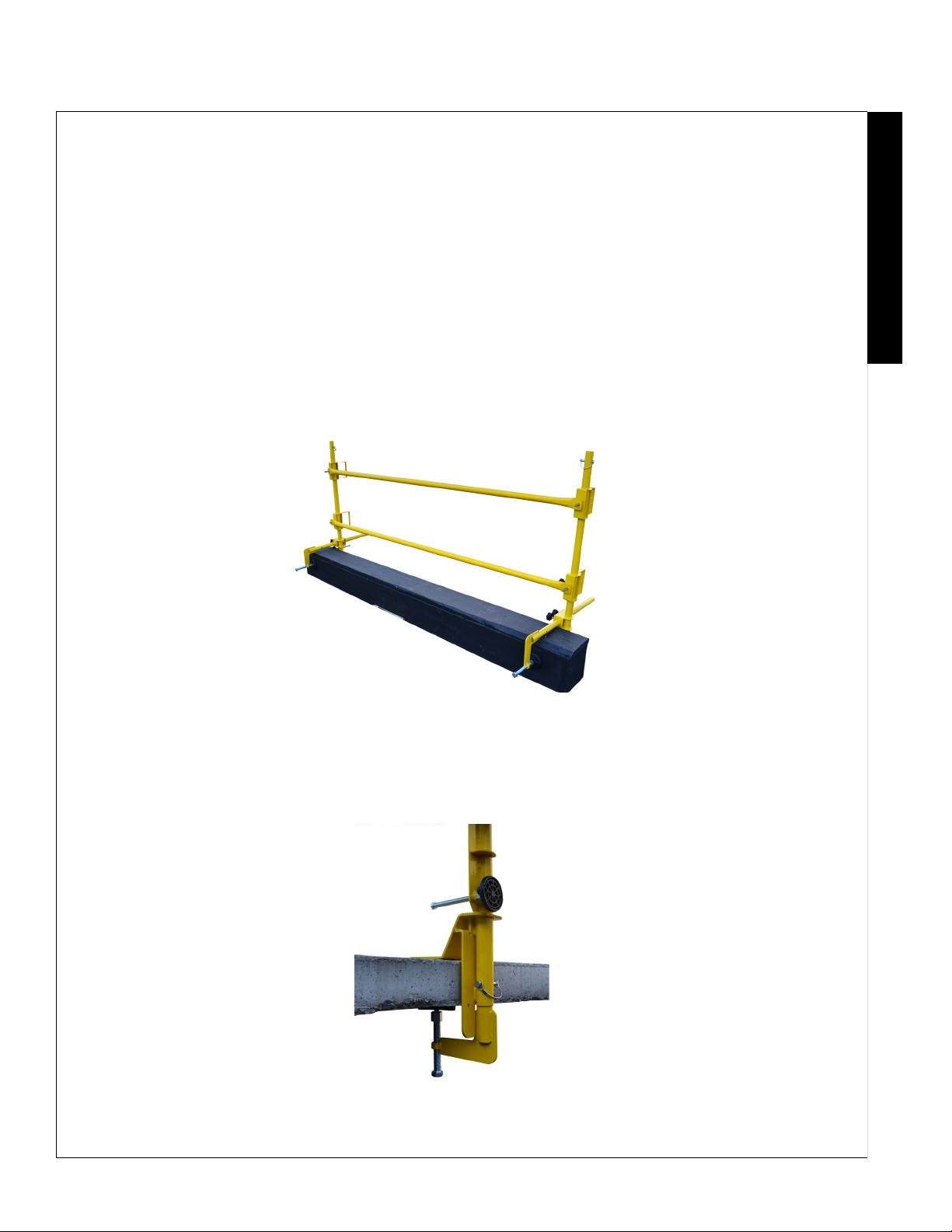
4.2 Tighten the clamp underneath the concrete slab unl the base is ghtly mounted to the concrete slab.
5.0 Installing the Horizontal Rails
5.1 All-In-OneTM can be used with metal RaptorRailTM rails or lumber rails.
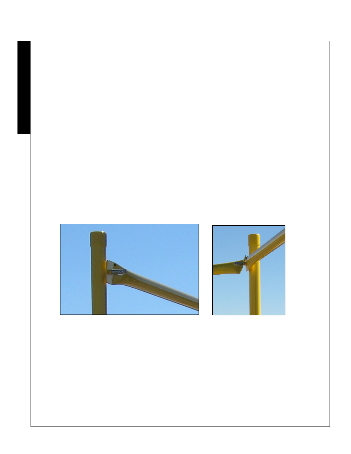
5.2 To install using metal RaptorRailTM Rails, install the bases the width of the rail (8’, 10’, or adjustable). Loosen the rail
brackets on the vercal posts and turn the brackets so that the railing drop-lock pins are facing in toward the working
surface. Then ghten the brackets using the ghtening knobs so that the top rail is 42” +/- 3” above the walking/
working level. Lastly, slide the metal RaptorRailTM onto the droplock pins.
5.3 To install using wood rails, cut the lumber no more than 9’ long. The lumber rail must overlap on either side of the posts
by 6”. The posts in a wood rail system must be spaced a maximum of 8’. Install the posts and bases at a maximum of 8’
apart. Loosen the rail brackets on the vercal posts and turn the brackets so that the wood brackets are facing in to-
ward the working surface. Then ghten the brackets using the ghtening knobs so that the top rail is 42” +/- 3” above
the walking/working level. Slide the wooden rails into the brackets and secure using at least two wood screws.
6.0 General Installaon Tips
6.1 Aer aaching the corner, begin seng up the addional bases at approximately 10 foot intervals. A good technique to
ensure the best possible t is to connect a top rail to an already mounted/xed base, set up the approximate posion of
the next base, connect the rail to the top pin, and set up the base in a vercal posion. Then connect the mid-rail.
When the post/base is connected and veried to be in a fully upright or vercal posion, aach the base either using
mounng screws or, if using the oponal parapet clamps, ghten the clamp.
6.2 Connue this process unl the railing system is complete, or unl the next corner locaon. At the corner, place the two
corner post/bases no less than 18" and no more than 27" from the actual corner. If the distance between your last post/
base and the corner post/base just installed is less than 10 feet, use the adjustable rails for opmum t.
7.0 Applicaons
7.1 The All-In-OneTM is to be used as a railing system for roofs and intermediate level oors. The All-In-OneTM may be used
where worker mobility and fall protecon are required.
7.2 The All-In-OneTM should be used as a part of a complete fall protecon system plan.
E
N
G
L
I
S
H

ALL-IN-ONE™INSTRUCTION MANUAL
6
7.3 The All-In-OneTM can be used with many dierent types of roong, decking, edge, or parapets providing a competent
professional has determined that the roof, deck, or edge is capable of withstanding the weight of the All-In-OneTM
system, and the OSHA required ability to withstand a 200 pounds force applied outward or downward anywhere on
the All-In-OneTM system.
If the parapet clamps are used, a competent professional will need to determine if the parapet has sucient strength
to provide the proper safety margin. OSHA regulaons require that the system be able to withstand a force of 200
pounds applied in an outward or downward direcon at any point along the railing system. For more informaon,
refer to OSHA regulaon 1926.502 “Guardrail Systems”.
8.0 Damage to Rail
Aer sustaining damage: Equipment which has been subject to damaging forces must be removed from service immediately for
inspecon.
9.0 Before Each Use
9.1 OSHA 1926.502 requires that before operang the system there must be an inspecon for damaged equipment.
INSPECTION STEPS
STEP 1: Check for loose, bent or damaged parts.
STEP 2: Check fasteners/connectors for distoron, cracks, or other damage.
STEP 3: Check for corrosion on Parts.
MAINTENANCE AND CARE:
A. Inspect all AES Raptor equipment and parts before and aer each use.
B. Regularly inspect all fasteners. Damaged or missing parts can severely hinder the safety factor of the All-In-OneTM.
C. Maintain paint nish to prevent corrosion.
10.0 General Safety
10.1 USE COMMON SENSE! Most accidents can be avoided by using common sense and concentrang on the job to be done.
10.2 The All-In-OneTM system should not be used by persons whose ability or alertness is impaired by fague, intoxicang
beverages, illegal or prescripon drugs, or any other physical cause that exposes the user or others to injury.
10.3 Always wear proper safety are.
E
N
G
L
I
S
H

Copyright © 2020 by Leading Edge Safety, LLC
1345 Taney, North Kansas City, MO 64116
www.LeadingEdgeSafety.net
PRINTED IN THE UNITED STATES OF AMERICA
This manual suits for next models
1
Table of contents
Other Leading Edge Safety Equipment manuals
Popular Safety Equipment manuals by other brands

KRATOS SAFETY
KRATOS SAFETY Voras FA 20 300 02 manual

Code 3
Code 3 CT0010 Series Installation and operation instructions

MAC PARA
MAC PARA Aegis SQ Operating & Packing Instruction

Tecto Protection
Tecto Protection Airtec PAPR user manual

IKAR
IKAR HRA Series Instructions for the use and inspection records

Petzl
Petzl MGO OPEN 60 TECHNICAL NOTICE

Uwatec
Uwatec EASYDON Dryglove instruction manual

Bornack
Bornack RFZ 1 user manual

HACA LEITERN
HACA LEITERN 0529.1904 Instructions for assembly and use

MSA
MSA OptimAir 3000 Instructions for use

Innotech
Innotech BARRIER-STEIGLEITER manual

Hornady Security
Hornady Security RAPiD SAFE NIGHT GUARD owner's manual