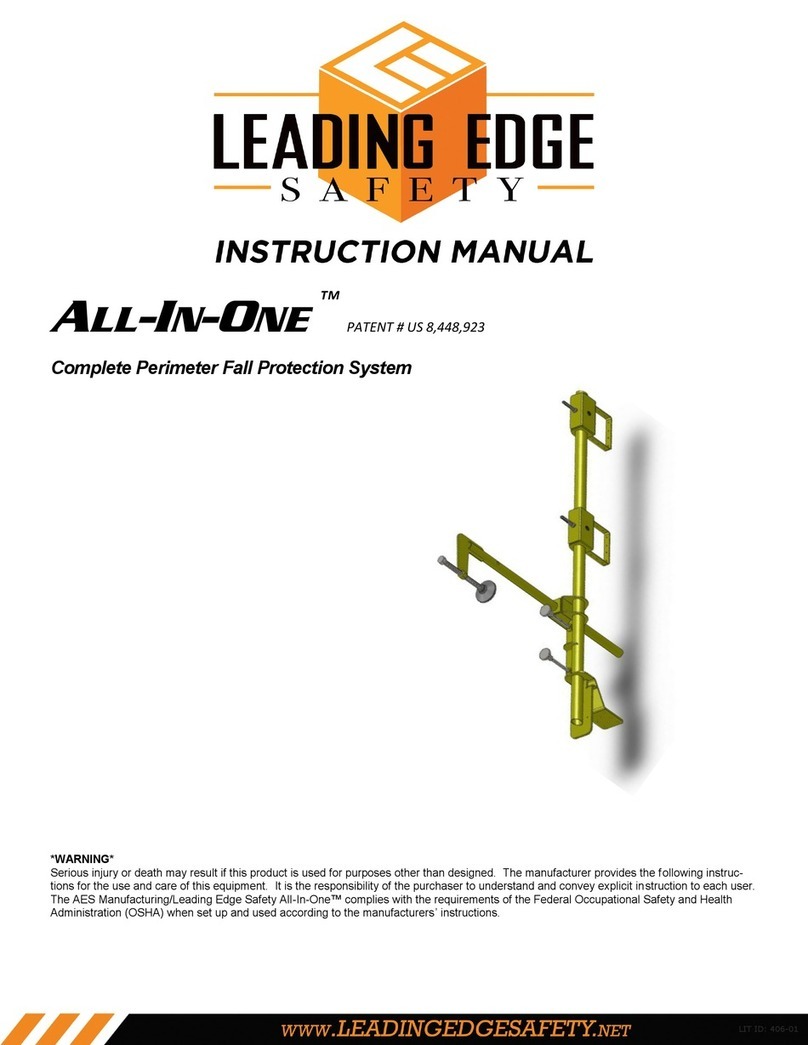
Leading Edge SAFETY BULL User manual

Safety Bull™ – 1
US
DK
DE
PL
SE
NO
FI
CZ
EL
ES
FR
IT
NL
RO
RU
SK
SR
TR
*WARNING*
Serious injury or death may result if this product is used for purposes other than designed. The
manufacturer provides the following instructions for the use and care of this equipment. It is
the responsibility of the purchaser to understand and convey explicit instruction to each user.
set up and used according to the manufacturers’ instructions.
Instruction Manual

1
2PLEASE COPY THIS LOG, FILL IT OUT BEFORE EACH USE, AND KEEP IT IN YOUR RECORDS.
3
4
5
6
7 8 9
10 Overall Cart Parts Yes
11
12 Welded Connection Yes
11
13 Safety Lifeline
Tie-off Rings and
Hoisting D-Rings
11
Yes
14
Cables Yes
11
15 Fall indicator Yes
11
16 Overall Cart Corrosion Yes
11

Safety Bull™ – 3
1. UK – SAFETYBULL INSPECTION AND
MAINTENANCE LOG
3.
Inspection date
8.
11.
13.
1. DK – SAFETY BULL EFTERSYNS- OG
VEDLIGEHOLDELSESLOG
3. Safety Bull serie
Safety Bull model
8.
Vogndele
11.
Svejset forbindelse
13. -
1. DE – INSPEKTIONS- UND
WARTUNGSPROTOKOLL SAFETY BULL
füllen Sie es vor jeder Benutzung aus
und archivieren Sie es.
3. Serie Safety Bull
8.
Wartung durchgeführt
Wagenteile insgesamt
11. Genehmigt durch
13. Zurrringe Sicherheitsleine und
1. PL – DZIENNIK KONTROLI I
KONSERWACJI SAFETY BULL
w swoich rejestrach.
3.
8.
11. Zatwierdzone przez
13. -
1. SE – INSPEKTIONS- OCH
SÄKERHETSLOGG FÖR SAFETYBULL
varje användning och spara den.
3.
8.
Övergripande vagndelar
11.
Svetsade anslutningar
13.
1. NO – SAFETY BULL INSPEKSJONS- OG
VEDLIKEHOLDSLOGG
sammen med papirene dine.
3.
Inspisert element notert
8.
Generelle vogndeler
11.
13.
1. FI – SAFETY BULLIN TARKISTUS- JA
KUNNOSAPITOLOKI
3. Safety Bullin sarjanumero
Safety Bullin malli
8.
11.
13.
1. CZ – PROTOKOL KONTROLY A ÚDRŽBY
ZAŘÍZENÍ SAFETYBULL
záznamech.
3.
8.
11. Schválil
13.
1. EL - ΑΡΧΕΙΟ ΚΑΤΑΓΡΑΦΗΣ
ΕΠΙΘΕΩΡΗΣΗΣ ΚΑΙ ΣΥΝΤΗΡΗΣΗΣ
SAFETY BULL
2. Αντιγράψτε αυτό το αρχείο κατα-
γραφής, συμπληρώνετέ το πριν
από κάθε χρήση και διατηρείτε το
στα αρχεία σας.
3. Αριθμός σειράς Safety Bull
4. Αριθμός μοντέλου Safety Bull
5. Ημερομηνία αγοράς
6. Ημερομηνία επιθεώρησης
7. Σημειώθηκε στοιχείο επιθεώ-
ρησης
8. Απαιτείται διορθωτική ενέργεια
9. Πραγματοποιήθηκε συντήρηση
10. Γενικά εξαρτήματα καλαθιού
11. Εγκρίθηκε από
12. Συγκολλημένη σύνδεση
13. Δακτύλιοι πρόσδεσης και
δακτύλιοι D ανύψωσης γραμμής
ζωής ασφάλειας
14. Καλώδια
15. Ένδειξη πτώσης
16. Γενική διάβρωση καλαθιού
1. ES - REGISTRO DE INSPECCIÓN Y
MANTENIMIENTO DEL SAFETY BULL
de cada uso y guárdelo en sus
archivos.
3.
8.
11.
Juntas de soldadura
13.
elevadores
1. FR - REGISTRE D’INSPECTION ET
D’ENTRETIEN DE SAFETY BULL
remplir avant chaque utilisation et le
conserver dans vos dossiers.
3. Série Safety Bull
8.
11.
13.
levage de sécurité de la ligne de vie
Indicateur de chute
1. IT - REGISTRO ISPEZIONI E
MANUTENZIONI SAFETY BULL
compilarlo prima di ogni uso e
conservarlo nei propri archivi.
3.
Voce ispezione annotata
8.
11.
13.
Indicatore di caduta
1. NL – INSPECTIE- EN
ONDERHOUDSLOGBOEK VOOR
SAFETYBULL
administratie.
3. Serienummer Safety Bull
Inspectiepunt genoteerd
8.
11.
13.
Valindicator
1. RO – JURNAL DE INSPECȚIE ȘI
ÎNTREȚINERE SAFETYBULL
dvs.
3.
8.
11.
13.
1. RU — ЖУРНАЛ ПРОВЕРКИ И
ТЕХОБСЛУЖИВАНИЯ УСТРОЙСТВА
SAFETY BULL
2. Скопируйте этот журнал,
заполняйте его перед каждым
использованием и храните в
своих записях.
3. Серийный номер устройства
Safety Bull
4. Модель устройства Safety Bull
5. Дата покупки
6. Дата проверки
7. Пункт проверки с примечанием
8. Необходимое корректирующее
действие
9. Проведенное техобслуживание
10. Все детали тележки
11. Утвердил
12. Сварное соединение
13. Кольца для пристегивания стра-
ховочного пояса и D-образные
кольца для подъема
14. Кабели
15. Индикатор падения
16. Коррозия всех частей тележки
1. SK – PROTOKOL KONTROLY A ÚDRŽBY
ZARIADENIA SAFETY BULL
3.
8.
11. Schválil
13.
1. BS – SAFETY BULL DNEVNIK INSPEKCE
I ODRŽAVANJA
3.
Safety Bull model
8.
11.
Vareni spoj
13.
Sajle
1. TR – SAFETY BULL DENETİM VE BAKIM
GÜNLÜĞÜ
3.
8.
11.
13.

Inspection log
1
2
3
4
5
6Batch or serial number
7
8
9-
10 -
expert
11
future references.

UK – INSPECTION LOG
1. Installer
Installation date
3.
Batch or serial number
8.
examination
11.
installation documentation needs to be
stored for future references.
DK – PRØVNINGSBOG
1.
3.
8.
11.
opbevares til fremtidig brug.
DE – PRÜFBUCH
1.
3. Standort
8.
Instandsetzungen etc.“
11.
aufbewahrt werden.
PL – KSIĄŻKA KONTROLI
1.
3.
8.
naprawy itp.
11.
przechowywana do odniesienia w
SE – BESIKTNINGSPROTOKOLL
1.
3. Säte
Batch- och serienummer
8.
reparationer osv.
-
11.
-
referens.
NO – PRØVEPROTOKOLL
1.
3. Sted
8.
reparasjoner osv.
11.
for fremtidig referanse.
FI – TARKASTUSKIRJA
1.
3.
8.
11.
CZ – KONTROLNÍ KNIHA
1.
3.
8.
opravy atd.
11.
EL - ΒΙΒΛΙΟ ΕΛΕΓΧΟΥ
1. Όνομα εταιρείας συναρμολό-
γησης
2. Ημερομηνία συναρμολόγησης
3. Τόπος
4. Ημερομηνία θέσης σε λειτουργία
5. Περιγραφή τύπου, πρότυπο
6. Αριθμός παρτίδας και σειράς
7. Ημερομηνία
8. Λόγος επεξεργασίας (τακτικός
έλεγχος ή επισκευή)
9. Ζημιές που διαπιστώθηκαν,
επισκευές που εκτελέστηκαν κτλ.
10. Όνομα και υπογραφή του
ελεγκτή/υπευθύνου
11. Επόμενος έλεγχος
Σύμφωνα με τον Κανόνα 112-198 του
DGUV, τα έγγραφα για την εγκατά-
σταση πρέπει να αποθηκεύονται για
μελλοντική αναφορά.
ES - CUADERNO DE INSPECCIÓN
1.
3.
8.
experto
11.
consultas posteriores.
FR - REGISTRE DE CONTRÔLE
1. Société de montage
3.
8.
de l’expert
11.
doit être conservée pour référence
ultérieure.
IT - REGISTRO DI CONTROLLO
1.
3.
8.
etc.
esperto
11.
documentazione inerente l’installazione
deve essere conservata per consulta-
zioni future.
NL – INSPECTIE LOGBOEK
1.
3.
8. -
reparatie etc.
11. Volgende inspectie
moet de installatiedocumentatie
RO – JURNAL DE VERIFICARE
1.
3.
8.
11.
RU – DENNÍK KONTROLY
1. Názov montážnej rmy
2. Dátum montáže
3. Miesto
4. Dátum uvedenia do prevádzky
5. Typové označenie, norma
6. Číslo šarže a série
7. Dátum
8. Dôvod úpravy (pravidelná
kontrola alebo údržba)
9. Zistené škody, vykonané práce
údržby atď.
10. Meno a podpis skúšajúceho/
kompetentnej osoby
11. Nasledujúca skúška
В соответствии с Правилом 112-198
DGUV, документация по монтажу
должна храниться для дальней-
шего использования.
SK – ZÁZNAM O KONTROLE
1.
3.
8.
11.
BS – EVIDENCA INSPEKCE
1.
3.
8.
11.
TR – KONTROL KAYIT DEFTERİ
1.
3.
8.
11.
-

Assembly manual:
1
A
2
16mm | 5/8”
20Nm | 15lbf ft

1
B
4
2
5
3

8 – Safety Bull™
1
1
1
C
D
E
2
2

1
3
F
2
4
1
4
2
3
E

US
DIAGRAM OF PARTS
Job Box
Side bars
KEEP BRAKE LOCKED UNLESS MOVING CART

Safety Bull™ – 11
US
1. ASSEMBLY
1.1 -
bly instructions for Safety Bull.
2. APPLICATIONS
in a complete mobile fall protection system.
mobility and fall protection are required.
See www.cen.eu for all regulations and
standards.
3. IMPORTANT
3.1 These safety instructions must be studied
carefully prior to the use of the anchorage
using this anchorage system should read
safety instructions. The manufacturer’s
instructions should be strictly observed.
Should a product be distributed in a country
distributor is responsible for ensuring that a
user manual is supplied in the corresponding
local language.
3.3
the anchorage system without the explicit
negatively impact the operation of the
anchorage system and pose a threat to the
user‘s safety.
4. SAFETY GUIDELINES
The recommendations for using other
products in conjunction with this product
must be observed.
The anchorage system was developed to
secure individuals and may not be used for
-
manual for details on the max. number of
individuals allowed to simultaneously use
the anchorage system.
The anchorage system may only be used
by appropriately instructed and trained
personnel.
to cover all possible emergency situations
-
ment.
The use of the anchorage system is not
suitable steps to ensure that the dynamic
force resulting from a fall does not exceed
in any way whatsoever.
service and examined by the manufacturer.
chemicals or other aggressive substances.
-
facturer.
Stainless steel components must not come
into contact with sanding dust or steel tools
as this can cause corrosion.
In case of doubt regarding the safe operation
-
tively the manufacturer should be informed
accordingly.
other object in case of a fall. When calculat-
allow for the fact that the anchorage system
fall. The arresting distance is calculated as
•
•

US
•
•
• -
•
heights.
Should there be any doubt as to the user’s
-
cian prior to usage.
the system.
If the anchorage system is to be used by
user manuals should be handed over in
written form together with these safety
instructions.
for reasons of safety. This is permissible.
too much force as this could lead to defor-
mation of the fall indicator on the anchoring
point. The fall indicator has been specially
The anchoring device is not to be used
for the positioning or abseiling of people
DROP/FALL DISTANCE
2
6
4
5
3
EXAMPLE 1
≥ 2,5 m
2
6
4
5
3
EXAMPLE 2

Safety Bull™ – 13
US
1
5
6
2
4
3
EXAMPLE 3
1
2
3
4
5
6
5. COMPATIBLE EQUIPMENT
The anchorage system must be used in
combination with personal fall protection
-
-
individual component is guaranteed and that
they do not interfere with each other.
only lanyards which are suitable for the
respective application and which have been
incidents resulting from the use of non-com-
patible equipment.
-
connector should render a fall impossible.
of non-compliance.
important to ensure the shortest possible
fall distance.
6. ANNUAL INSPECTION
for having it inspected at regular intervals
according to the respective operating
conditions – by an expert trained and cer-
in perfect condition. This is a general rule
which applies regardless of whether the
anchorage device has actually been used
inspection is important as the user‘s safety
the equipment.
document contained in these instructions
may be used as a template.
legibility during the annual inspection.
service.
7. WARRANTY
We grant a 1 year guarantee against man-
ufacturing faults on all components used
the system be implemented in an environ-
-

US
to absorb energy and which may possibly be
8. SAMPLE LABEL
Product: Anchor device
Model: SafetyBull EU-000-18
Year of Manufacture:
Serial Number:
Number of Users: 1-2
SafetyBull A/S Roskildevej 342 DK-2630 Taastrup
www.SafetyBull.com/info@safetybull.com +45 80 40 56 45
Testet according to EN 795:2012, CEN/TS 16415:2017
Type: SafetyBull
3
2
4
5
6
7
8
2
19
1
2Standards
3
4
5
6Serial number XX XXXXX-XXXX
7
8
9
9. USE AND LIMITATIONS
2 persons:
B
G
I
J
N
O
-
•
•
• Ice
• Snow
•
10. CONCRETE USE LIMITATIONS
When applicable to ANSI/ASSE Z359.6-2009 /
OSHA 1926.502(d)(15) the
concrete fall arrest of a
maximum of 2 (two) when 145+ kg is added to
the SafetyBull.
10.2 When applicable to DIN EN 795:2012, DIN
CEN/TS 16415:2017the SafetyBull™ is rated
for 4,000 - 6,000 psi concrete fall arrest of a
maximum of 1 (one) when 145+ kg is added to
the SafetyBull.
3
8
11. CAPACITY:
11.1
designed for a maximum of two persons for
time.
installed onto is capable of supporting the
assessment of the entire surrounding area
surfaces have the strength and structural
integrity to support users safely.
11.3
•

US
•
are pointing toward the leading edge and
the cart is set to travel parallel to the
12. MAKING CONNECTIONS:
remove from service immediately and
information visit www.safetybull.com and
use connectors that are suitable for each
not use equipment that is not compatible.
13. BEFORE EACH USE:
13.1
there must be an inspection for damaged
equipment.
INSPECTION STEPS:
indicator is present and undamaged.

US
and cable connections have been damaged.
legible.
-
ment plate for freedom of movement.
of movement.
replacement parts.
The fall indicator located at the pin connec-
13.3
•
and parts before and after each use.
•
build-up on the tires can cause the
•
•
prolong the life of the unit or system and will
contribute to the performance of its vital
or lyes for cleaning! We recommend the use
-
14. GENERAL SAFETY
be avoided by using common sense and
concentrating on the job to be done.
whose ability or alertness is impaired by
cause that exposes the user or others to
injury.
power lines.
cart.
in use.
debris.
-
sition for which it has been tested.
attached to the roof.
common sense when moving the unit.
15. HOISTING:
death.
overhead lifting.
standards and the manufacturer’s recom-
mendations.
-
Secure auxiliary equipment and material
a crane with the use of a four-leg wire rope

US
-
HOISTING DIAGRAM
Table of contents
Other Leading Edge Safety Equipment manuals
Popular Safety Equipment manuals by other brands

KRATOS SAFETY
KRATOS SAFETY Voras FA 20 300 02 manual

Code 3
Code 3 CT0010 Series Installation and operation instructions

MAC PARA
MAC PARA Aegis SQ Operating & Packing Instruction

Tecto Protection
Tecto Protection Airtec PAPR user manual

IKAR
IKAR HRA Series Instructions for the use and inspection records

Petzl
Petzl MGO OPEN 60 TECHNICAL NOTICE

Uwatec
Uwatec EASYDON Dryglove instruction manual

Bornack
Bornack RFZ 1 user manual

HACA LEITERN
HACA LEITERN 0529.1904 Instructions for assembly and use

MSA
MSA OptimAir 3000 Instructions for use

Innotech
Innotech BARRIER-STEIGLEITER manual

Hornady Security
Hornady Security RAPiD SAFE NIGHT GUARD owner's manual