Inputting numbers
Pressing any key on the numeric keypad can input the
correspondent number.
For example, pressing will generate the number
"8".
Numeric Keypad
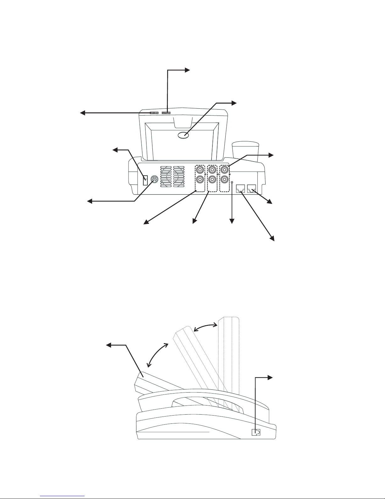
Front view (cont.'d)
8
TUV
2
ABC
1
@_-
3
DEF
5
JKL
6
MNO
4
GHI
9
WXYZ
8
TUV
7
PQRS
0
!;$
.,
Numeric Keypad
Inputting letters
Every button on the numeric keypad has characters printed
on it, in addition to the numbers. Number keys from"2"to"
9 " have English letters on them, so they can be used to input English letters.
When inputting data, pressing a key consecutively will generate the letters on it.
For example, has the number"7"andthealphabets " PQRS " on it.
Pressing this key once will generate the number"7".
Pressing this key twice consecutively will generate the letter"P".
Pressing this key three times consecutively will generate the letter"Q".
Pressing this key four times consecutively will generate the letter"R".
Pressing this key five times consecutively will generate the letter"S".
And it will cycle in such order.
7
PQRS
Inputting punctuation marks
The keypad provides four punctuation marks:
" " " " " " and " ".
.,! ;
" ": Press twice consecutively;
" ": Press three times consecutively.
" ": Press twice consecutively.
" ": Press three times consecutively.
.
,
!
;
Press only once to generate"."when inputting IP addresses.
.,
.,
0
!;$
0
!;$
Inputting special characters
The keypad also provides six special characters: " " " " " " " " " "
and " ".
@_- $
#
" ": Press twice consecutively; " ": Press once.
" ": Press three times consecutively. " ": Press 4 times.
" ": Press four times consecutively. " ": Press once.
@
_$
-#
1
@_-
1
@_-
1
@_-
.,
0
!;$
Switching between upper
case and lower case letters
Press once to switch
between upper and lower case
letters when inputting data.
Speed Dial
When the handset is picked up
or the button is
pressed, pressing can
enable speed dial.
speaker
Videophone User's Manual 5