Leclerc Looms ARTISAT 36 inch User manual

1
1573 Savoie
C. P. 4 Plessisville, Qc.
G6L 2Y6
TEL: 819-362-7207
FAX: 819-362-2045
www.leclerclooms.com
Loom Prepared by:_____________
Inspected by:_________________
Date:____________________
On receiving the loom, unpack and lay
out the loom components.
Do NOT discard any packing material until all
parts are inventoried.
Check the parts received against the
parts list on pages #2 to #6 of the assembly
instructions. Report any discrepancies to
Leclerc immediately.
To assemble this loom, a minimum of 2
people are needed but it is recommended
you use 3.
ARTISAT 36” JACK-TYPE
8 SHAFTS BACK HINGE
TREADLES
1009-3628
14 1/8"
IMPORTANT

2
PARTS LIST
8 FLOATING LAMS
1 CASTLE TOP COVER
1 LEFT-HAND SIDE
with base packed seperatly
1 RIGHT-HAND SIDE
with base and brake treadle packed
seperatly
1 friction control system bolt
1 FRONT CROSS-MEMBER
1 MIDDLE LOWER CROSS-MEMBER
1 TREADLE ROD 27 ¾” with one push nut
1 MORE PUSH NUT 7/16”
2 TREADLE set SUPPORTS
41½ cc
Note for Leclerc in French:
4) Corde de frein coton 40"
5) Surveiller l'amanchement
avec les pattes avant.
39¾"
Note for Leclerc in
French:
1) Poser les 2 vis de la
base de pattes arrière pour
le crochet.
Tête ronde no 12, 1" avec
rondelle de nylon
2) Poser la pièce letée
du contrôle de friction sur
la patte arrière gauche.
3) Faire les trous sur les
sabots pour le séparateur
de pédale + les trous pour
pentures

3
1 PK. 10 YDS FOR BEAM STICK
1 PK 5 YDS FOR BEAMING AND LEASE
STICKS
1 SHUTTLE
1 DOZ. BOBINES 4"
1 CLOTH BEAM WITH RATCHET
WHEEL (wood = 38 1/8")
1 WARP BEAM WITH BRAKE DRUM
(wood = 38 7/8")
1 TAKE-UP MOTION HANDLE
1 BATTEN HANDTREE
1 BATTEN SLEY WITH SHUTTLE RACE
2 BREAST BEAMS

4
36 1/8"
31¼"
1 JACK BOX
(DO NOT REMOVE THE
TAPE UNTILL IT IS
INSTALLED IN THE LOOM)
10 treadles with rocker piece
1 stabilizing post cross member
assembly with 2 stabilizing
back posts
1 Treadle Separator 40” long
10 Treadle springs with
Loop cords 9”
(back part)
20 3/8"
Note for Leclerc in French: La
planche avant et arrière de la
boite à marmousset doit avoir
les vis pour cordes à bascule
et ressort à pédale
2 X 10 vis #12 x ¸¾”

5
10.5"
10.5"
8 SHAFT (harness) FRAMES
1 REED
2 LEASE STICKS
1 BEAM STICK
3 WARP RODS
1000 HEDDLES
1 HEDDLE AND REED HOOK 8 5/8” long
6140-9000
1 Black Screwdriver
1 Red Screwdriver
1 Adjustment wrench
10 treadle hooks 10”
10 pegs to lock the treadle hooks
60 TREADLE CORDS 6½”
1 CRANK FOR BACK BEAM

6
0
1"
2"
3"
4"
Machine bolts
1X 7/16 X 3½" (12 mm X 90 mm)
1 - 9/16 cloth beam
2 - 9/16” treadle set
4 - 5/16” (8 mm)
5 - ¼" (6 mm) SQUARE NUTS
2 - ¼” (6 mm)
2 - 5/16” (8 mm)
1½” 9x Wooden spacers
Wing nuts
6 X - ¼” (6 mm)
2X - 5/16” (8 mm)
Round head screws
6 - #14 X 2” (50 mm)
2 - #8, 1¼” (treadles separator)
8 - #12, 1½” (jack box)
6 - #8, 1” (stab. post hinges)
6 - #14, 2½" (base)
Flat head screws
4X - #12 X 1½” (38 mm)
(castle top)
2X eye screws
10 Loop cords 18½” long for treadle rocker
Instruction Video
showing all stages of the
installation.
Carriage Bolts
2 - ¼ X 3¼” (6 mm x 80 mm) (F. Cross-Member)
2 - ¼” X 3” (6 mm x 75 mm) (Treadle blocs)
2 - ¼” X 1¾” (6 mm x 45 mm)
4 - 5/16 X 2½” (8 mm x 65 mm)
2 - 1/4” X 2¼” (stab. hook)

7
Lay the left side on the oor with
caution (you can put a piece of
cardboard on the oor). Removed
the packing material and using
three #14 round head screw 2½",
afx the base to the left upright
and the back post to the base.
#14 round head screw 2½"
Lay the right side on the oor with
caution (you can put a piece of
cardboard on the oor). Removed
the packing material and using
three #14 round head screw 2½",
afx the base (the brake treadle is
already installed) to the right up-
right and the back post to the base.

8
ATTENTION: Application of soap to the
screws will make their insertion easier.
Place right-hand side A straight up beside the
wall.
Using a 2” (50-mm) round-headed screw no 14,
afx lower middle cross-member B to the bot-
tom of left-hand side A.
The lower middle cross-member has a hole at
either end; the narrow sides B1 must be above
and under the cross-member and the wide faces
B2 must be on the sides.
Unfold the front section of left-hand side A. Using
a ¼” x 1¾ (6mm x 45mm) carriage bolt and a ¼”
(6mm) wing nut, afx metal hook C to left-hand
side front post D.
Using a ¼” x 1¾” (6mm x 45mm) carriage bolt
and a ¼” (6mm) wing nut, afx metal hook C’ to
right-hand side front post D’.

9
Place the take-up motion handle E, with a
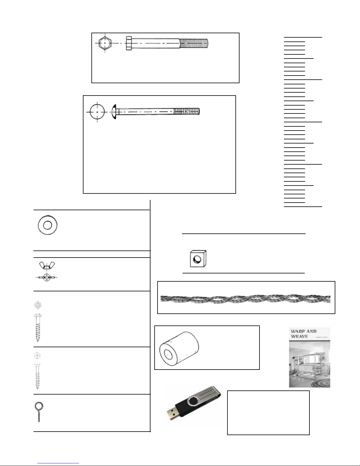
9/16” steel
washer, on the right-hand side end of cloth
beam F.
Note: The ratchet gear is on the right-hand
side beam end.
The ratchet pawl afxed to the take-up mo-
tion handle must be lifted up.
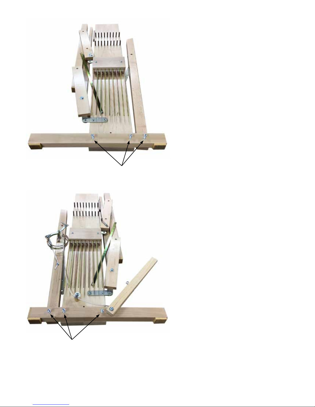
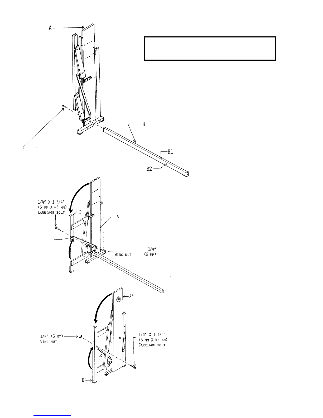
Insert the end of cloth beam F into the holes
in upper front cross-members G and G` The
hole in lower middle cross-member B must
be right beside the hole at the bottom of
right-hand side A`
Using a 2” (50 mm) round-headed screw
no. 14, afx right-hand side A` to lower
middle cross-member B.
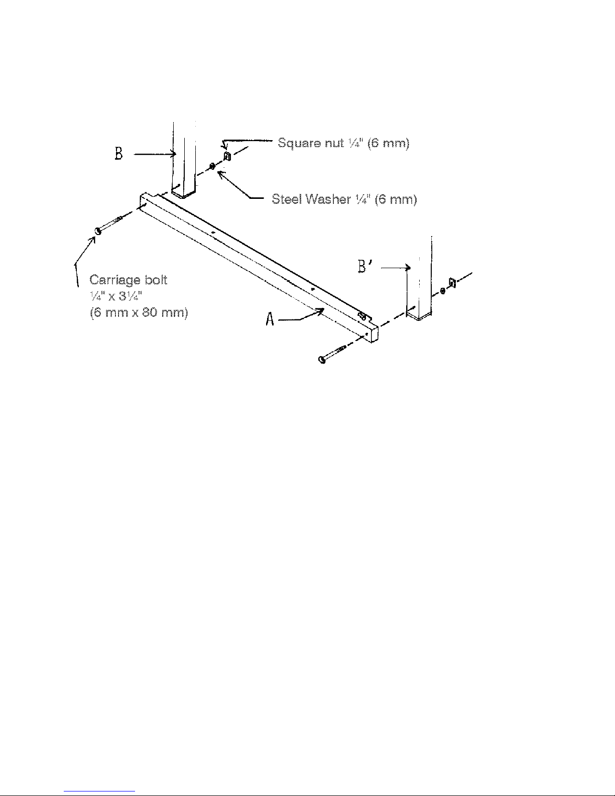
Using two 2” (50 mm) round-headed screws
no. 14, afx one of the two breast beams to
the top of the front posts B and B`
The rounded edge must be towards the out-
side of the loom.

10
Using ¼” x 3¼” (6mm x 80mm) carriage bolts, plus ¼” (6mm) steel washer and square nuts,
attach front cross-member A to front posts B and B`

11
ATTACHING THE STABILIZING ASSEMBLY TO THE LOOM
Install the rear Stabilizing assembly (A) to the Warp Beam Posts using 6 Round Head Screws #8 - 1”
Anchor the hook (B) to the stabilizing post of the loom using 2 carriage bolts ¼” - 2¼” and 2 wing nuts
¼” (the wings nuts go on the outside of the loom)
Wing nut
A
B
12"
TO GROUND
14¼"
Carriage bolts ¼" - 2¼

12
TREADLE SEPARATOR
Afx the Treadle Separator Board on top of the back of the side base
and secure using 2 #8, 1¼” Round Head Screws.
TREADLE SET ASSEMBLY
Assemble the treadle
set (in or out of the loom)
as shown in picture
using:
1 treadle rod 27¾”
10 treadles
9 wood spacers
2 treadle blocks
2 x 9/16" washers
2 X push nuts 7/16”
(one is already on the rod)
Afx treadle set to the treadle
cross-member using:
2 carriage bolts ¼” x 3”
2 washers ¼” (under cross member)
2 Wing nuts ¼”
Treadle
Block
Place one washer between the last treadle and the treadle blocks.

13
Slide jack box B along the middle posts A, from bottom to top, and afx it to
blocks C using eight 1½” (40 mm) round-headed screws no. 12.
NOTE: The 10 screws go in the front bottom of the loom.
The eyescrews go in the back bottom of the loom.
Install the heddles in the shaft
frames. (see “WARP AND
WEAVE” on page 10)
Remove the saran wrap on the
jack box.
Slide shaft frames T between
dividers Q.
The shaft frames must rest on
the plastic supports U of the
jacks
NOTE: Some shafts may be
tight between the castle frame
until the castle top is attached.
The Leclerc Logo goes
in the top front of the
shaft frame
The ratchet pawl Q afxed
to the Side Loom must be
lifted up while inserting
the Jack Box.
Q

14
Join the “S” hook of the jacks D to the eyelet of the
FLOATING lam E.
Castle cover
Complete the assembly by secur-
ing the Castle cover with 4 #12
1½” at screws.
Make sure to screw into the pre-
drilled holes of the castle.

15
Install the treadle cords with the treadle hooks.
Using the carriage bolts, steel washers and square nuts, attach the batten sley A (with shuttle race) to
the batten swords B.
Then afx the batten handtree C to the batten swords B.
Install reed D in the slots of batten
handtree C and batten sley A.
Adjust batten handtree C by sliding
the bolts in the slots of the batten
swords to rmly hold the reed.

16
If the batten does not touch the two bumpers equally, loosen
the bolts of the batten sley and batten handtree and exert
pressure on the batten centering it in its proper place. Tighten
the bolts again.
You can install now or just before weaving the treadles springs.
After the installation, the treadles will be all at the same height.

17
Unhook brake treadle cord C from the brake release treadle.
Hold circular wire brake shoe D up slightly to the rear of the loom.
Insert one end of the warp beam (which has only a metal post) into the left-hand
side back post.
Insert the friction brake drum of the warp beam into the circular wire brake shoe D.
Do not unroll the brake shoe (brake circle), just slide the warp beam into it

18
Insert the brake end of the warp
beam into the hole of the right-hand
side back-post.
Install the 7/16” X 3½” machine bolt through the right-hand
side back post and into the warp beam.
Using crank E, tighten the machine bolt into the warp beam.

19
Using two 2” round-headed screws no 14, afx the breast
back beam to the back posts.
Join the front “S” hook of the brake lever to the brake loop cord so the tension on the spring will be
high enough to lock the warp beam while weaving.
The warp beam should turn with some friction clockwise (while standing at the right side
of the loom near the brake system) and this is the warping rotation. However, you should always
release the tension on the friction brake system by disconnecting the spring from the loop cord (S
hook) when you are warping the loom.
To advance the fabric when weaving, depress the brake treadle just enough to release the
warp beam. Depressing the brake treadle too far may cause the brake cable to come off the brake
drum.
Join the brake treadle to the S Hook in the back of the Brake Lever. Adjust the length so the bake
treadle is at the comfortable height Make a double knot at the brake treadle eye.

20
Threading Hook
FIRST TREADLE TIE-UP
Select any treadle and tie the Lams to the Treadles using
the 7½” cords supplied with the loom. Use the threading
hook to help pass the cord through each hole of the lam.
Install the Treadle Rocker Loop Cord on the
Jack box screw at the black mark as a starting
point.
TREADLE HOOK AND ROCKER LOOP CORD
Slide the Treadle Hook through the Screw
Eyes and the treadle Cord Loops. Before the last
Screw Eye, insert the Hook through the
Treadle Spring loop cord and secure with the peg
in the front.
In the Treadle rest position(up) there should be no
or very little tension on the Spring.
However, slack on the spring cords is not
desirable.
When all treadles are tied up, they should
be at almost the same height. The top front part of
each treadle should be app. at 8¾" to the floor.
Jack box screw
Rocker loop cord
Loop cord of the Treadle spring
Fig. 24
This manual suits for next models
1
Table of contents
Other Leclerc Looms Other manuals
Popular Other manuals by other brands

Rheem
Rheem RRNA-B SERIES installation instructions

CARVIN
CARVIN GUITAR CARE maintenance

Sencor
Sencor SBS 2700 user manual

Horizon Fitness
Horizon Fitness VERT series Installation and operation manual

DITEC
DITEC Entrematic XEL5 Installation handbook

CEMO
CEMO Trolley 60 l AdBlue Car PRO operating instructions