manuals.online logo
Brands
  1. Home
  2. •
  3. Brands
  4. •
  5. LEGRAND
  6. •
  7. Accessories
  8. •
  9. LEGRAND HPM 630R01WE User manual

LEGRAND HPM 630R01WE User manual

This manual suits for next models

1

Other LEGRAND Accessories manuals

LEGRAND Wattstopper DW-311-I User manual

LEGRAND

LEGRAND Wattstopper DW-311-I User manual

LEGRAND HPM Serenity User manual

LEGRAND

LEGRAND HPM Serenity User manual

LEGRAND 5 742 00 User manual

LEGRAND

LEGRAND 5 742 00 User manual

LEGRAND Wattstopper UT-305-1 User manual

LEGRAND

LEGRAND Wattstopper UT-305-1 User manual

LEGRAND C2G 50190 User manual

LEGRAND

LEGRAND C2G 50190 User manual

LEGRAND PW-100-347 User manual

LEGRAND

LEGRAND PW-100-347 User manual

LEGRAND adorne APCB2 User manual

LEGRAND

LEGRAND adorne APCB2 User manual

LEGRAND Raritan LVC-101G2 User manual

LEGRAND

LEGRAND Raritan LVC-101G2 User manual

LEGRAND 896 30 User manual

LEGRAND

LEGRAND 896 30 User manual

LEGRAND WattStopper DW-100 User manual

LEGRAND

LEGRAND WattStopper DW-100 User manual

LEGRAND Radiant WWRR15LACCV2 User manual

LEGRAND

LEGRAND Radiant WWRR15LACCV2 User manual

LEGRAND 0 546 00 User manual

LEGRAND

LEGRAND 0 546 00 User manual

LEGRAND 5 742 54 User manual

LEGRAND

LEGRAND 5 742 54 User manual

LEGRAND DX2 Series User manual

LEGRAND

LEGRAND DX2 Series User manual

LEGRAND 0 624 15 User manual

LEGRAND

LEGRAND 0 624 15 User manual

LEGRAND Pass & Seymour WA1001 Manual

LEGRAND

LEGRAND Pass & Seymour WA1001 Manual

LEGRAND WIREMOLD deQuorum DQFF15BK User manual

LEGRAND

LEGRAND WIREMOLD deQuorum DQFF15BK User manual

LEGRAND Pass & Seymour WSP251 User manual

LEGRAND

LEGRAND Pass & Seymour WSP251 User manual

LEGRAND Plexo 695 56 User manual

LEGRAND

LEGRAND Plexo 695 56 User manual

LEGRAND 094219 User manual

LEGRAND

LEGRAND 094219 User manual

LEGRAND Wattstopper FSP-321B User manual

LEGRAND

LEGRAND Wattstopper FSP-321B User manual

LEGRAND adorne ARTRUSB153 User manual

LEGRAND

LEGRAND adorne ARTRUSB153 User manual

LEGRAND WattStopper DW-100-24-LA User manual

LEGRAND

LEGRAND WattStopper DW-100-24-LA User manual

LEGRAND Radiant Series User manual

LEGRAND

LEGRAND Radiant Series User manual

Popular Accessories manuals by other brands

Quincy lab 140AE-1 operating manual

Quincy lab

Quincy lab 140AE-1 operating manual

HomePro ZIR000 user manual

HomePro

HomePro ZIR000 user manual

DOL 20SCR Technical user guide

DOL

DOL 20SCR Technical user guide

RAB Smart Task installation manual

RAB

RAB Smart Task installation manual

Kemppi KMS 300 quick guide

Kemppi

Kemppi KMS 300 quick guide

Stearns 57,500 Series Installation and service instructions

Stearns

Stearns 57,500 Series Installation and service instructions

iGuzzini TWILIGHT COPENAGHEN manual

iGuzzini

iGuzzini TWILIGHT COPENAGHEN manual

Adelaide Annexe & Canvas Avan Deluxe installation guide

Adelaide Annexe & Canvas

Adelaide Annexe & Canvas Avan Deluxe installation guide

OHAUS 5000 instruction manual

OHAUS

OHAUS 5000 instruction manual

HOME8 WLS1300 quick start guide

HOME8

HOME8 WLS1300 quick start guide

MAXBOTIX MaxSonar quick start guide

MAXBOTIX

MAXBOTIX MaxSonar quick start guide

ioSmart iSmart56 Installation and user guide

ioSmart

ioSmart iSmart56 Installation and user guide

Focusrite Scarlett 18i8 user guide

Focusrite

Focusrite Scarlett 18i8 user guide

Velleman ED38105 user manual

Velleman

Velleman ED38105 user manual

JumpSport SkyBounce user manual

JumpSport

JumpSport SkyBounce user manual

Prima-Temp PRIYA Instructions for use

Prima-Temp

Prima-Temp PRIYA Instructions for use

Tefcold BC85I-BC85I W user manual

Tefcold

Tefcold BC85I-BC85I W user manual

Vaisala WMS302 user guide

Vaisala

Vaisala WMS302 user guide

manuals.online logo
manuals.online logoBrands
  • About & Mission
  • Contact us
  • Privacy Policy
  • Terms and Conditions

Copyright 2025 Manuals.Online. All Rights Reserved.

PIR Movement Sensors
Instruction Manual
Cat. 630R01WE, 630R01BL
1 Specifications
Cat No 630R01WE 630R01BL
Detection Method Passive Infrared (PIR)
Supply Voltage 230-240V a.c. 50Hz
Terminal Wiring Size 1 x 2.5mm2 to 2 x 1.5mm2
Standby Power < 1.0W
Detection / View Angle 360°
Detection Range (ceiling height 4m) Ø6m (at ≤ 24°C)
Recommended Mounting Height 2.2m to 4.0m
Lux Adjustment Range 3 lux to 2000 lux
Time Adjustment Range 10 ± 3 sec to 15 ± 2 min
Switching Function Auto Mode only
IP Rating IP20
Ceiling Cutout Size Ø40mm
Fascia Size Ø50mm
Depth into Ceiling 50mm
Weight 56g
Colour White Black
Cat No 630R01WE 630R01BL
Incandescent 800W
Fluorescent 400VA
Compact Fluorescent Lamp (CFL) 300VA
LED 300VA
This product must be installed by a licensed electrician
Fig. 1
Fig. 1
Max:3m Max:3m
360˚
Fig. 5
Fig. 4
Neutral
Active
Load
3 Where to mount your movement sensor
Before selecting a place to install your movement sensor, you should note that movement across the scan area is more effective than
movement directly toward or away from the sensor (refer to Fig. 2). If movement is made walking directly towards or away from the
sensor and not across, the apparent detection range will be substantially reduced.
Ideally, the sensor should be mounted 2.2m to 4.0m above the area to be scanned (refer to Fig. 1).
4 Installation
Fig. 2
Good Sensitivity Poor Sensitivity
Switch off power source before installation.
Ensure the power supply wiring comes from a circuit protected by a suitable fuse or circuit breaker.
We recommend installing a wall switch for electrical isolation of the sensor.
1. Cut out a Ø40mm hole in the ceiling.
2. Remove the terminal block cover by loosening the screw (Fig. 3).
3. Connect the supply & load cables to the terminal block as shown in Fig. 4. Ensure that the wires are secure and no bare wires are
exposed. This is a class II item, ensure this is maintained during installation.
4. Replace the terminal block cover & tighten the screw.
5. Fold back spring clips & insert unit into the ceiling cutout (Fig. 5).
6. Remove the Fascia by turning it in a counter-clockwise direction (Fig. 6).
7. Set the Controls as described in the next section.
8. Replace the Fascia.
Fig. 3
Fig. 6
Fascia
1. Near water features such as swimming pools or ponds. The movement and reflections are likely to create nuisance switching.
2. Near heat sources such as air conditioners, dryers, heaters or barbecues.
3. Locations which are subject to drastic changes in temperature.
4. Locations which are subject to bright light such as direct sunlight.
5. Locations frequented by animals such as pets or birds.
2 Sensor locations to be avoided
Fig. 2
Fig. 3 Fig. 5 Fig. 6
Fig. 4
Neutral
Active
Load
Fig. 4
5 Setting the Controls
Fig. 7
With the Sensor fully installed by an electrician and power on
1. Turn the TIME knob to minimum and turn the LUX knob to maximum as shown in Fig. 7.
2. Turn the wall switch on. The light/s should turn on immediately and will remain on while the sensor warms up, for approximately
30 seconds. It will then turn off.
3. Walk through the coverage area and the light should turn on. This confirms that the wiring is correct and that the light is operational.
4. Adjust the TIME knob to your desired setting.
5. To set the ambient light level at which the sensor will switch on, turn the LUX knob to its fully anti-clockwise position. Wait for the
desired ambient light level, then turn the LUX knob clockwise while someone walks through the coverage area. When the light
switches on, release the LUX knob.
6 Time Adjustment
The TIME knob controls how long the light/s will stay on after movement is detected. Rotating the TIME knob clockwise increases the
duration time. The duration time varies between approximately 10 seconds (minimum) to approximately 15 minutes (maximum).
Note: Once the light has been triggered by the PIR sensor, any subsequent detection will start the timed period again from the
beginning.
7 Lux Adjustment
The LUX knob controls the ambient light level at which the sensor will switch on. At the fully clockwise position, the sensor will operate
24 hours a day. At the fully anti-clockwise position, the sensor will only operate at night. You can set the sensor to operate at the
desired lux level by adjusting the LUX knob.
8 Maintenance / Cleaning
This product should only be cleaned with a damp cloth. Cleaning agents and solvents should not be used.
Fig. 7
9 Troubleshooting
Warranty
HPM Legrand warrants this product for a period of 3 years from the date of purchase.
These goods come with guarantees that cannot be excluded under the Australian
and New Zealand Consumer Laws. You are entitled to a replacement or a refund for
a major failure and for compensation for any other reasonably foreseeable loss or
damage. You are also entitled to have the goods repaired if the goods fail to be of
acceptable quality and the failure does not amount to a major failure.
See the Warranty card enclosed with this product for further details.
Customer Service
For all Customer Service and Technical Support
please call Monday to Friday during business hours.
LE09423AFA HPML1172
Disclaimers
1. This product must be installed and used as per these instructions.
2. The IP rating of this product is only valid when installed on a flat and non-porous surface. Additional sealing may be required for
irregular surfaces.
3. This product must be used with the loads specified only. Other load types should be used only when written confirmation is given by
HPM Legrand.
4. This product contains no serviceable parts and no attempt should be made to repair this product. If the product is faulty it should be
discarded.
5. This product is not suitable for installation in hazardous and/or corrosive areas.
6. Electrical installations periodically receive transient over voltages. This product has been designed to minimise the effect of such
voltages on connected equipment. It may not give full protection for extreme over-voltage transients such as those resulting from a
close lighting strike.
7. This product utilises intellectual property in the form of registered designs, trademarks, and/or patents. Such intellectual property
remains the property of HPM Legrand in all cases.
8. This product has been designed to operate in ambient temperatures -10°C to 40°C.
9. Extended exposure to UV rays (such as exposure to direct sunlight) may cause discolouration of this product.
10. The material in this product may vary in colour from batch to batch. Colour matching from one batch to another cannot be guaranteed.
11. HPM Legrand reserves the right to modify the specification of this product at any time.
Legrand Australia
1300 369 777
www.hpm.com.au
Legrand New Zealand
0800 476 009
www.hpm.co.nz
ABN: 31 000 102 661
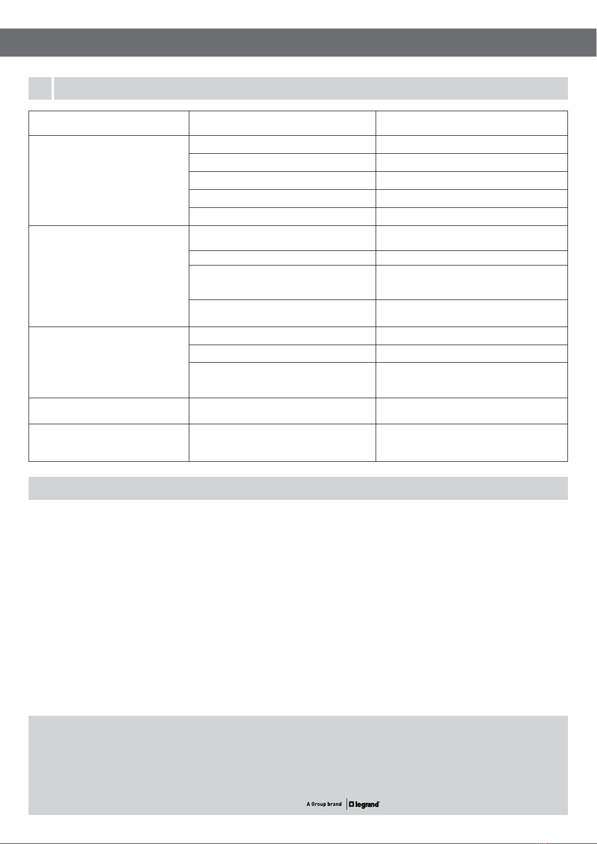
Problem Possible cause Possible solution
Light does not switch on when there is
movement in the coverage area.
1.Power not available Check connections, switches and fuse.
2. Faulty light/globe. Replace light/globe.
3. Incorrect wiring. Recheck all wiring.
4. Controls set incorrectly. Change light adjustment (LUX knob).
5. Nearby lighting is too bright. Relocate the unit.
Light switches on for no apparent reason.
(False triggering)
1. Heat sources (such as air conditioner, heater,
dryer or barbecue) are activating the sensor. Relocate the unit.
2. Animals (birds, pets etc) Possibly unavoidable.
3. Interference on the same circuit from on/off
switching of other electrical devices.
a. Check/Replace faulty switches.
b. Replace noisy fluoro tubes/starters.
c. Connect the unit to a different circuit.
4. Reflective objects (such as swimming pool) in
the coverage area. Relocate the unit.
Light does not switch off after set time
has elapsed.
1. Time is set for too long. Reduce time (TIME knob).
2. Wiring is incorrect. Recheck all wiring.
3. Unit damaged due to maximum load exceeded
or incompatible load type or failure of the load
(such as short circuit).
Identify and fix the cause of the failure.
Replace the unit with a new one.
Light switches on during daylight. 1. LUX knob is set to daylight position. Turn the LUX knob anti-clockwise to suit desired
light setting.
When setting the controls in daylight the
detection distance becomes shorter. 1. Interference by sunlight. Re-set controls at night.