Pass
&
Seymour
Dlegrand
®
Installing and
Testing a
GFCI Receptacle
Please read
this
leaflet
completely·before
getting started.
3. Should you install it?
Installing a GFCI receptacle can be
more complicated than installing a
conventional receptacle.
Make sure that you:
• Understand basic wiring principles
and techniques.
• Can interpret wiring diagrams.
• Have circuit wiring experience.
• Are prepared to take a few minutes
to test your work, making sure that
you have wired the GFCI receptacle
correctly.
A CAUTION
·To
prevent severe shock or electro-
cution, always turn the power OFF
at the service panel before working
with wiring.
• Use this GFCI receptacle with
copper or copper-clad wire. Do not
use it with aluminum wire.
·Do
not install this GFCI receptacle
on a circuit that powers life support
equipment because if the GFCI
trips, it will shut down the
equipment.
• For installation
in
wet locations,
protect the GFCI receptacle with a
weatherproof cover that will keep
both the receptacle and any
plugs dry.
• Must be installed
in
accordance
with national and local electrical
codes.
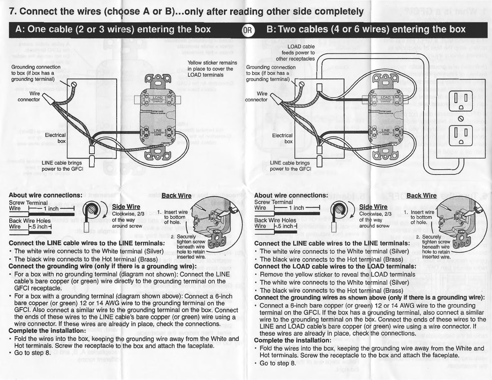
4. LINE vs. LOAD
A cable consists of 2 or 3 wires.
Cable Wires
''"'"'""'"~
LINE cable:
Delivers power from the service panel
(breaker panel or fuse box) to the
GFCI. If there is only one cable enter-
ing the electrical box, it is the LINE
cable. This cable should be connected
to the GFCl's LINE terminals only.
LOAD
cable:
Delivers power from the GFCI to
another receptacle in the circuit. This
cable should be connected to the
GFCl's LOAD terminals only. The LOAD
terminals are under the yellow sticker.
Do not remove the sticker at this time.
1. What is a GFCI?
A GFCI receptacle is different from
conventional receptacles.
In
the event
of a ground fault, a GFCI will trip and
quickly stop the flow of electricity to
prevent serious injury.
Definition
of
a ground fault:
Instead of following its normal safe
path, electricity passes through a
person's body to reach the ground.
For example, a defective appliance
can cause a ground fault.
A GFCI receptacle does
IlQ1
protect
against circuit overloads, short circuits,
or shocks. For example, you can still be
shocked
if
you touch bare wires while
standing on a non-conducting surface
such as a wood floor.
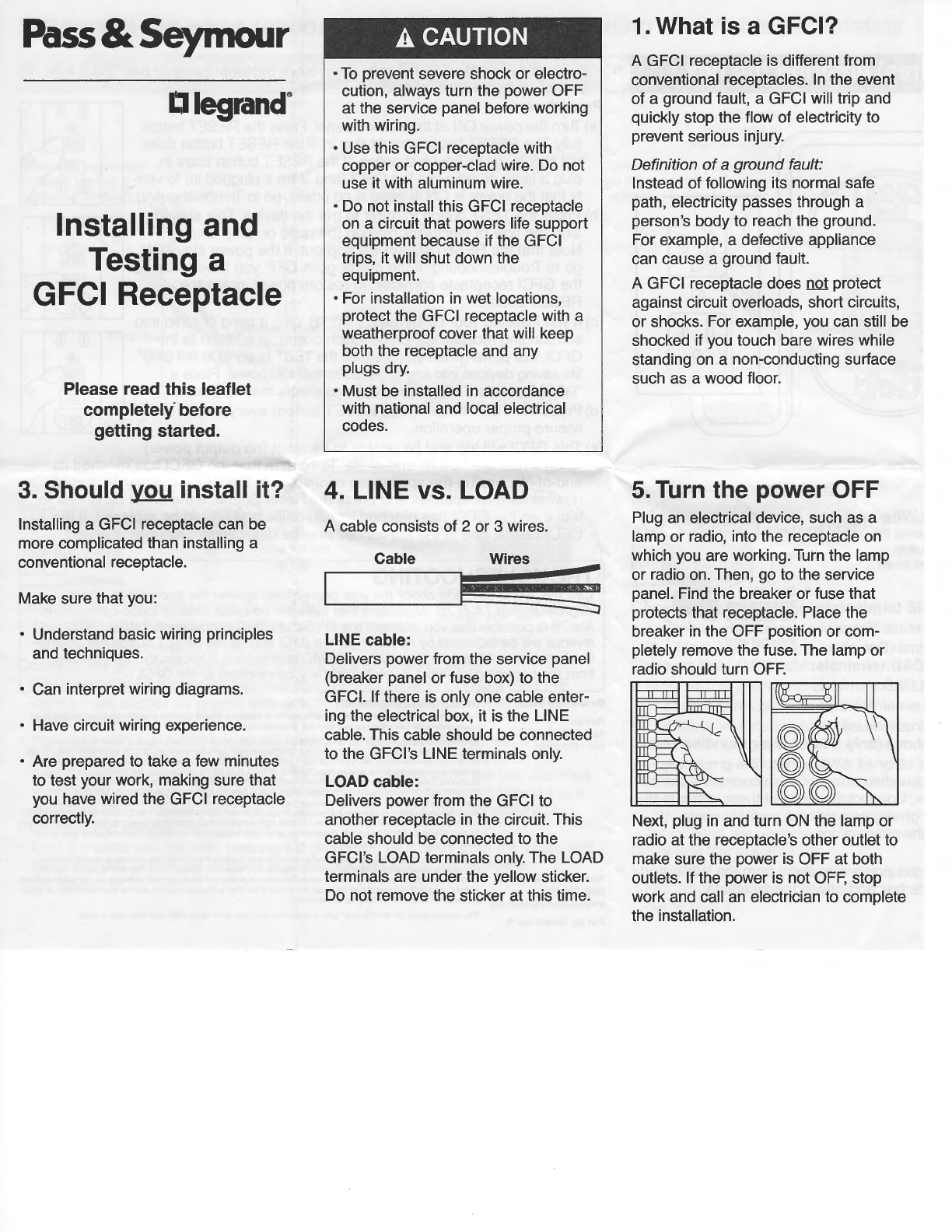
5.
Turn the power OFF
Plug an electrical device, such as a
lamp or radio, into the receptacle on
which you are working. Turn the lamp
or radio on. Then, go to the service
panel. Find the breaker or fuse that
protects that receptacle. Place the
breaker
in
the OFF position or com-
pletely remove the fuse. The lamp or
radio should turn OFF.
Next, plug
in
and turn ON the lamp or
radio at the receptacle's other outlet to
make sure the power is OFF at both
outlets. If the power
is
not
OFF,
stop
work and call an electrician to complete
the installation.