LEGRAND 4 306 26 User manual

USER MANUAL
IP vidéo Decoder 4ch D1
4 306 26
LE05113AA

2
Table of contents
1General Introduction ........................................................................................................................ 4
1.1 Specification .................................................................................................................................4
1.2 Feature..........................................................................................................................................5
2Front panel / Real panel / Installation............................................................................................ 7
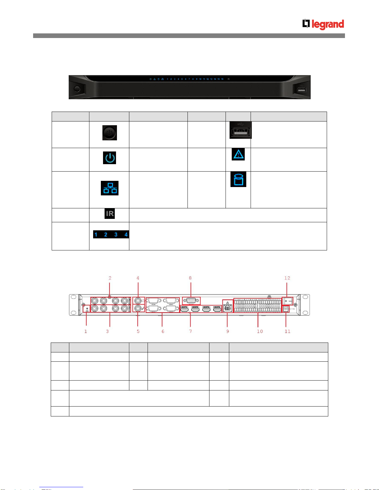
2.1 Front panel....................................................................................................................................7
2.2 Rear Panel.....................................................................................................................................7
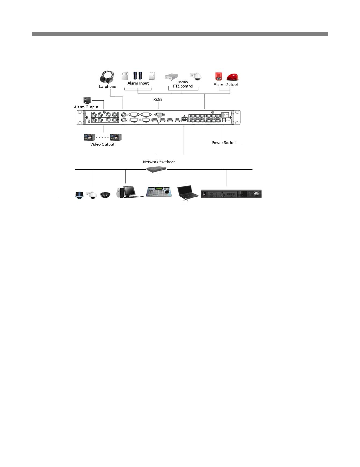
2.3 Connection....................................................................................................................................8
2.3.1 General Connection............................................................................................................................................................. 8
2.3.2 Audio/Video Connection...................................................................................................................................................... 8
2.3.3 Audio Talk Input Connection................................................................................................................................................ 8
2.3.4 Video Output Device and Connection.................................................................................................................................. 8
2.3.5 Audio Output........................................................................................................................................................................ 8
3Operation........................................................................................................................................... 9
3.1 Boot Up and Shut Down ...............................................................................................................9
3.2 Login.............................................................................................................................................9
3.2.1 Preparation.......................................................................................................................................................................... 9
3.2.2 Login.................................................................................................................................................................................. 10
3.3 Main Window...............................................................................................................................11
3.3.1 Decode Channel Information............................................................................................................................................. 12
3.3.2 Decode Channel Setup...................................................................................................................................................... 12
3.3.3 Add /Remove Front-end Device ........................................................................................................................................ 12
3.3.4 File Playback and Time Playback...................................................................................................................................... 13
3.4 Decoder Configuration ...............................................................................................................14
3.4.1 Tour Config....................................................................................................................................................................... 14
3.4.2 Decode Output.................................................................................................................................................................. 15
3.4.3 Video Output...................................................................................................................................................................... 15
3.4.4 TV Adjust........................................................................................................................................................................... 16
3.4.5 Decode Tour...................................................................................................................................................................... 16
3.4.6 Decode strategy................................................................................................................................................................ 17
3.5 Configuration..............................................................................................................................18
3.5.1 System Information............................................................................................................................................................ 18
3.5.2 System Configuration........................................................................................................................................................ 19
3.5.3 Advanced........................................................................................................................................................................... 26
3.5.4 Additional Function............................................................................................................................................................ 27
3.6 Alarm...........................................................................................................................................27
3.7 About ..........................................................................................................................................28
3.8 Log out........................................................................................................................................28
4Alarm Input and Output ................................................................................................................. 28

3
4.1 Alarm Input Port..........................................................................................................................29
4.2 Alarm Output Port.......................................................................................................................29
4.3 Alarm Output Relay Specification ..............................................................................................30
4.3.1 Contact parameters........................................................................................................................................................... 30

4
1 General Introduction
1.1 Specification
System
Parameter
Device Model
4 306 26
Main Processor
High performance industry embedded micro processor
OS
Embedded LINUX
Input Device
Front panel button and keyboard
Shortcut Menu
N/A
Hardware Port
Specification
Video Standard
MPEG4/H.264
Audio Standard
PCM/G711
Decode Display
Resolution
QCIF/CIF/2CIF/ HD1/D1/720P/1080P
Video Frame Rate
PAL:1~25f/s;NTSC:1~30f/s
Bit stream Type
Composite stream/Video stream
Video Output
Channel
4 channels
Video Output Port
VGA/HDMI/BNC
Audio Output
Channel
4 channels
Audio Output Port
HDMI/BNC(Level: 200-3000 mV. Resistance: 5Ω)
Communication Port
One RJ45 10M/ 100M/1000M self-adaptive Ethernet port
One RS232 port
2 duplex RS485
Audio Talk Channel
1 channel
Audio Talk Port
BNC(Level: 2Vrms. Output resistance : 10k ohms)
Alarm input
16 channel
Alarm Output
8-ch relay output (30VDC 1A.125VAC 0/5A activation output)
Working
Environment
and Other
Physical
Specification
Power
DC12V, 5.0A
Power Consumption
≤40W
Working
Temperature
0℃-+55℃
Working Humidity
10%-90% 86kpa-106kpa
Dimension(mm)
440×300×42.1 mm
Weight
3.00—3.50KG

5
1.2 Feature
Network
Property Setup
Network parameter setup such as IP, getaway, subnet mask. Support remote
control.
NTP
Synchronize system time via NTP service.
DHCP
Automatically get network parameter such as IP parameter.
Auto get
After you configured the front-end encode device information, decoder can
automatically connect to the encode device and then begin work
independently and reliably,
Passive receive
In transmit mode, decoder can get the random data bit stream from the
network server to realize decoding output.
Output
Window Split
The first TV supports 1/4/9/16 window split; the second/third/fourth TV
supports 1/4/ window split
Tour
The product has four output interface sets
( VGA,HDMI,TV are contained in each set)
Both two products can realize real-time surveillance via monitor and support
any tour output of 1/4/9 window split or sequence combination, in addition,
both products support decode tour
Alarm
External Alarm
Multiple-channel relay alarm output to activate the peripheral alarm device
(such as on-site light control), manual control and activation video output.
Decoder Alarm
Prompt current decode status in time.
Precaution
Measure
Alarm input port and alarm output port both have protection electricity to
guarantee main device safety.
COM
Common COM
Device debug console.
Network Keyboard
The key board can control the device via network port.
Control Keyboard
The key board can control the device via RS232 port.
Transparent COM
Transparent COM function/
Decode
Decode Capability
NVS0404DH max. supports 28 D1 decode output(2M code-stream), there are
14 720P decode output (4M, the main core for 8 channels, the minor cores for
2 channels each) and 7 1080P decode output (8M, the main core for 4
channels, the minor cores for 1 channel each)
Auto check current decode loading and prompt user decode abnormal event.
Real-time stream
decode
Get the local real-time bit stream of the encoder and then output.
Previous stream
decode
Get the local previous bit stream of the encoder and then output.
Message
feedback
All application ends can accurately get current decoding status.
User
Management
Account
Management
Add, modify, and delete user or user group.
Modify user password.
Right
Management
Set different rights for different users.
Security
Management
Password protection.
Three times login failure may result in account lock.

6
Others
Version
Information
Display device important hardware port information, software version
information and etc.
Log Search
Record device important log. Support search by type.
Time
Synchronization
Set system time manually or synchronization PC time.
Language Option
English
DST
Set proper DST time according to different regions’setup.
Auto maintenance
Auto maintain device regularly.
DNS
Domain service
Upgrade
Support various upgrade types such as U disk, network, and TFTP.
Intelligent
Operation
Support copy function for the same setup.

7
2 Front panel / Real panel / Installation
2.1 Front panel
Name
Icon
Function
Name
Icon
Function
Power button
Press it for three
seconds to boot up or
shut down the device.
USB port
Connect to external USB
device.
Power
indication
light
The indication light
becomes on when
system boots up.
Alarm
indication
light
N/A
Network
indication
light
The indication light
becomes on when
abnormal network
event occurs (offline,
IP conflict and etc.)
HDD
indication
light
N/A
IR receiver
N/A
TV indication
light
When device is in TV working mode.
Only the channel 1 to channel 4 indication lights are effective
The rest channels 5 to channel 16 indication lights are null right now.
2.2 Rear Panel
SN
Port Name
SN
Port Name
SN
Port Name
1
Ground screw hole
2
Audio output port(BNC)
3
Video output port (BNC)
4
Audio talk output
port
5
Audio talk input
port
6
VGA port
7
HDMI port
8
RS232 port
11
Power plug port
9
Network interface(10M/100M/1000Mself-adaptive
Ethernet port)
12
Power switch
10
Relay input, relay output, duplexRS485 port

8
2.3 Connection
2.3.1 General Connection
2.3.2 Audio/Video Connection
All audio and video data are encoding from the front-end device and then input to the network via RJ45 port.
2.3.3 Audio Talk Input Connection
It adopts BNC port.
2.3.4 Video Output Device and Connection
The product adopts four output sets. VGA, HDMI and BNC a set; BNC(1.0VP-P ,75Ω).
2.3.5 Audio Output
The audio output parameter of NVS is 200mv 1KΩ(BNC), it can connect directly to low impedance earphone, active sound boxor
amplifier-drive audio output device.
If the sound box and the pick-up cannot be separated spatially, it is easy to arouse squeaking. In this case you can adopt the following
measures:
Use pick-up with better directing property.
Reduce the volume of the sound box until there is no squeaking.
Using more sound-absorbing materials in decoration to reduce voice echo and improve acoustics environment.
Adjust the layout to reduce risk of the squeaking.

9
3 Operation
3.1 Boot Up and Shut Down
Boot up
Connect the NVS to the power and then press the power button in the front panel. You can see the power indication light becomes on
and NVS boots up.
The system is in multiple-window display mode by default.
Shut down
You can press power button in the front panel for three seconds to shut down the device.
System Restore after Power Failure
When decoder is working, if the power failure occurs, the system can automatically connect to the front-end device and restore
previous working status once the power connection becomes normal.
3.2 Login
3.2.1 Preparation
Before log in, please make sure:
NVS connection is OK.
You have set PC IP address, NVS IP address, subnet mask and gateway. (Please set the IP address of the same section for the PC
and NVS. Please input corresponding gateway and subnetmask if there are routers.) When NVS booted up normally, please input
account name admin and password admin via the PC COM port., then input net –a and then input IP, NETMASK, GATEWAY. The
command mode is: net -a [IP] [NETMASDK] [GATEWAY].
For example:
Username: admin
Password: admin
DeBug>net -a 192.168.XXX.XXX 255.255.XXX.XXX 192.168.XXX.XXX
Use order ping ***.***.***.***(NVS IP address) to check connection is OK or not. Usually the return TTL value should be less than 255.
Open IE and then input the address in the column.
WEB control can be downloaded and installed automatically. System can download the latest Web control and remove the old one.
You can run uninstall web.bat to remove the control
System is compatible with web control of WINVISTA. But you need to disable account control item and then reboot the PC.

10
3.2.2 Login
Open the IE and then input the NVS IP address in the address column.
For example, if your NVS IP address is 192.168.1.100, then please input http:// 192.168.1.100 in IE address column.
System pops up warning information to ask you whether install webrec.cab control or not. Please click yes button.
If you can’t download the ActiveX file, please modify your settings as follows.
After installation, the interface is shown as below.
Please input your user name and password.
Default factory name is admin and password is admin.
Note: For security reasons, please modify your password after you first login.
Input IP address
here.

11
3.3 Main Window
After login successfully, the interface will be shown as below
There are eight sections:
Section 1: Decode channel
There are 28 decode channels. There are four TVs corresponding to four output sets. Click four icons on the upper left to choose.
There are 16 channels in the first TV, please see Figure3-4. There are four channels in the second/third/fourth TV respectively.
TV 1: Decode channel 1 to decode channel 16.
TV2: Decode channel 17 to decode channel 20.
TV3: Decode channel 21 to decode channel 24.
TV4: Decode channel 25 to decode channel 28.
Section 2: Close full-screen monitor
Only close the monitor of the channels of the chosen TV.
Section 3 Channel mapping
For the channel that currently choosing TV only
Section 4 Window split
There are four display modes, namely, single-split, 1/4/9/16 window split. Take the first TV for an example: there are 16 options for
single-split: channel 1, Channel 2……channels 16; 4 options for four-window split: 1-4ch, 5-8 ch, 9-12 ch, 13-16 ch; 2 options for nine-
window split: 1-9ch, 8-16ch; one option for 16-window split: 1-16channel.
Section 5: System menu. Please read the user's manual for further reference.
Section6: Here you can view device channel information. You can add/delete decoder front-end device and realize file playback and
time playback function. There are two shortcut options: mapping channel and close full-screen monitor.
Section7: Bidirectional talk. Please select the corresponding audio talk mode from the drop down list and then enable this function.
Click reboot button you can reboot current device.
Section8: There are three buttons: Play/pause/stop.

12
3.3.1 Decode Channel Information
Single click and choose any decode channel to connect real-time decode output.
1. Front-end device IP address.
2. Front-end real-time monitor channel.
3. The real-monitor channel connection status between the decoder and the front-end.
4. It is a button to control the connection between the decoder and the front-end.
3.3.2 Decode Channel Setup
Please select the output TV and position and then select the device channel in the device list. Double click channel name or drag the
channel name to the destination position and then release, you can see system pops up a dialogue box to inform that your setup is
valid.
3.3.3 Add /Remove Front-end Device
Add device
Click the add device button in the main window. System pops up the following dialogue box.
After inputting the corresponding information, please click OK button. You can see the device begins to connect the newly added front-
end device.
Once the connection is OK, you can see the channel information in section 3.
Delete Device
Select one front-end device and then click delete device button, system can remove it from the list.

13
3.3.4 File Playback and Time Playback
You can select a device you want to playback and then select the corresponding playback mode. There are two modes: file playback
and time playback.
File Playback
Please select the decode channel and then select a front-end (on-line) to playback. Please click the device name and then click file
playback button; you can see an interface is shown as below.
Please select record playback mode, and then select start time, end time and channel. Then please click search button, you can see
the corresponding files in the list.
Select the file first and then click playback button, you can view the video.
Double click decode channel, you can view in full screen.
The playback bar is shown as below.
The three buttons ranges from left to the right are: playback, pause, and stop.
Note:
In parameter column, you can click the dropdown list and then select the corresponding date.
When device is play backing in the decode channel, you can view the related information in current Web. Once you exit the Web and
then log in again, or you log in the Web in another PC, you can not view that current decode channel is playback right now.
If you searched device is offline, system prompts “Channel search failed”or “No record”.

14
Time Playback
Please select the decode channel and then select a front-end (on-line) to playback. Please click the device name and then click time
playback button; you can see an interface is shown as below.
Please select corresponding time period and channel, and then click playback button, system can playback automatically.
The playback bar is the same with file playback mode.
3.4 Decoder Configuration
3.4.1 Tour Config
Here you can set decode output channel and tour channel.
Set decoder output channels and tour channels: any output TV can tour at any channel of this device and execute 1/4/9 window tour.
TV output: You can select decoder output TV.
Windows selection: Here you can select single-split, 1/4 or 1/9 window output mode.
Video channel: You can select output decode channel.
TV output
Choose window-mode
Decode channel
1,2,3,4
Single-window
Display in two lines:
1-16 and 17-28
1,2,3,4
1/4 window
1-4
5-8
9-12
13-16
17-20
21-24
25-28
Note: there are no 1/9-window tour in TV2, TV3 and TV4.

15
3.4.2 Decode Output
The decode output interface is shown as below.
Here you can view current decode information.
Status: Current channel working status. There are four statuses: Monitor/Playback/Decode/Free.
Resolution: Here you can view video resolution.
FPS: You can view the frame rate.
Data Flow: You can view the network data flow current channel received.
Decode flow: You can view the output video flow current channel decoded.
3.4.3 Video Output
The video output interface is shown as below.
Set the resolution of decoder, which is the resolution of the output TV. Supports three resolutions: 1280x1024,1208x720 and
1920x1080. Here you can view there are two connection modes: direction connection and forward connection. When you use WEB or
PSS (Professional surveillance software) to control the device, the device is in direction connection type. When you use DSS to control
the device, the device is in forward mode.
Important:
The connection mode here is read-only.

16
3.4.4 TV Adjust
Here you can adjust the TV display margin.
You can select the TV number and then drag the slide bar to adjust.
3.4.5 Decode Tour
Decode tour: each decode channel is bounded with 32 channels on web. Each channel on the web will be displayed in accordance to
the channel and internal which are previously set in turn.
The decode tour interface is shown as below.
Parameters
Video: Here you can select the decode channel. The value ranges are from 1 to 28. IP: The front-end device IP address.
Port: The front device port value.
Channel: The tour channel of the front-end device.
Stream: The front-end stream type. There are two options: main stream and extra stream.
User: The user name you use to login the front-end device. Please make sure it is useable (Multiple users can use current
account to login at the same time)
Password: The password you use to login the front-end device.
Interval; The period video displayed in current channel. The value ranges from 10 to 120 seconds.

17
Buttons
Add: After you set the decode channel, IP address etc, please click the add button, the device information will be added to the
list on the right panel (Please note it has not been saved in the device.)
Delete: Select an item in the list and then click the button to remove. Please note you need to click save button to complete
the operation (That is to say, you need to click save button to remove the information in the device.)
Modify: Double click an item in the list you can modify the device information. Click modify button to save current modification.
Please note current information has not been saved in the device.
Delete all: Click it to remove all device information in the list. It is to clear all decode tour setups.
Save: Click it to save the setup on the right panel to the device.
Search: Click it to search the tour setup information of corresponding decode channel.
Start: Click it to begin the decode tour of the specified channel.
Stop: Click it to stop the decode tour setup of the specified channel.
Pause: Click it to pause tour. Current tour will be displayed in the channel all the long.
Resume: Click it to resume tour. The tour gets activated and then begins from the next tour setup.
Export: Export all tour setups of the device.
Import: Import all tour setups of the device.
Setup steps:
1. Set the parameters of decode channel, such as IP and channel, then click “add”, the device info will be added into the list on
the right.
2. Click “save” to save those to the device.
3. Click “start” to start the decode tour of the chosen channel.
3.4.6 Decode strategy
Set the delay time of decoder in each decode channel, the buffer time is ms.
Parameters
Explanation
Channel number
Channel 1-28 are available
decoding buffer time
Selectable range: 80~480

18
3.5 Configuration
3.5.1 System Information
Version Information
Here you can view device hardware feature and software version information.
Log
Here you can view system log.
Click backup button, the interface is shown as below.

19
Please refer to the following sheet for log parameter information.
Parameter
Function
Type
Log types include: system operation, configuration operation, alarm event, user
management, log clear.
Search
You can select log type from the drop down list and then click search button to
view the list.
Clear
You can click this button to delete all displayed log files.
Backup
You can click this button to backup log files to current PC.
3.5.2 System Configuration
Please click save button to save your current setup.
General Setup
Here you can set system time, DST, video format and etc.

20
Please refer to the following sheet for detailed information.
Parameter
Function
System Time
Here is for you to modify system time. Please click Save button after your
completed modification
Sync PC
You can click this button to save the system time as your PC current time.
DST
Here you can set day night save time begin time and end time.
Language
You can select the language from the dropdown list. Device needs to reboot to
get the modification activated.
Video
Standard
You can select video format such as PAL. You need to reboot the device to
activate current setup.
Local
Number
Default number 8
RS232
The RS232 interface is shown as below.
Table of contents
Other LEGRAND Media Converter manuals

LEGRAND
LEGRAND C2G 29503 User manual

LEGRAND
LEGRAND 4 130 12 User manual

LEGRAND
LEGRAND LCST 0 335 07 User manual

LEGRAND
LEGRAND UTP-Fiber1G-USB User manual

LEGRAND
LEGRAND Raritan D4CBL-ADUPS2 User manual

LEGRAND
LEGRAND VADDIO EasyIP Decoder User manual

LEGRAND
LEGRAND LVD-102 User manual

LEGRAND
LEGRAND Galea life User manual

LEGRAND
LEGRAND VADDIO AV Bridge Nano User manual

LEGRAND
LEGRAND 4 130 15 User manual