LEGRAND MOSAIC Series User manual

INSTALLATION AND USER GUIDE
TECHNICAL GUIDE
THE GLOBAL SPECIALIST IN ELECTRICAL
AND DIGITAL BUILDING INFRASTRUCTURES
MOSAIC
NURSE CALL UNIT

2
Contents
DESCRIPTION OF THE SYSTEM ARCHITECTURE >>>>>>>>>>>>>>>>>>>>>>>>>>>>>>>>>>>>>>>3
Fundamental rules to follow when installing the Mosaic nurse call system >>>>>>>>>>>>>>>>>>>>>>>>>>>>3
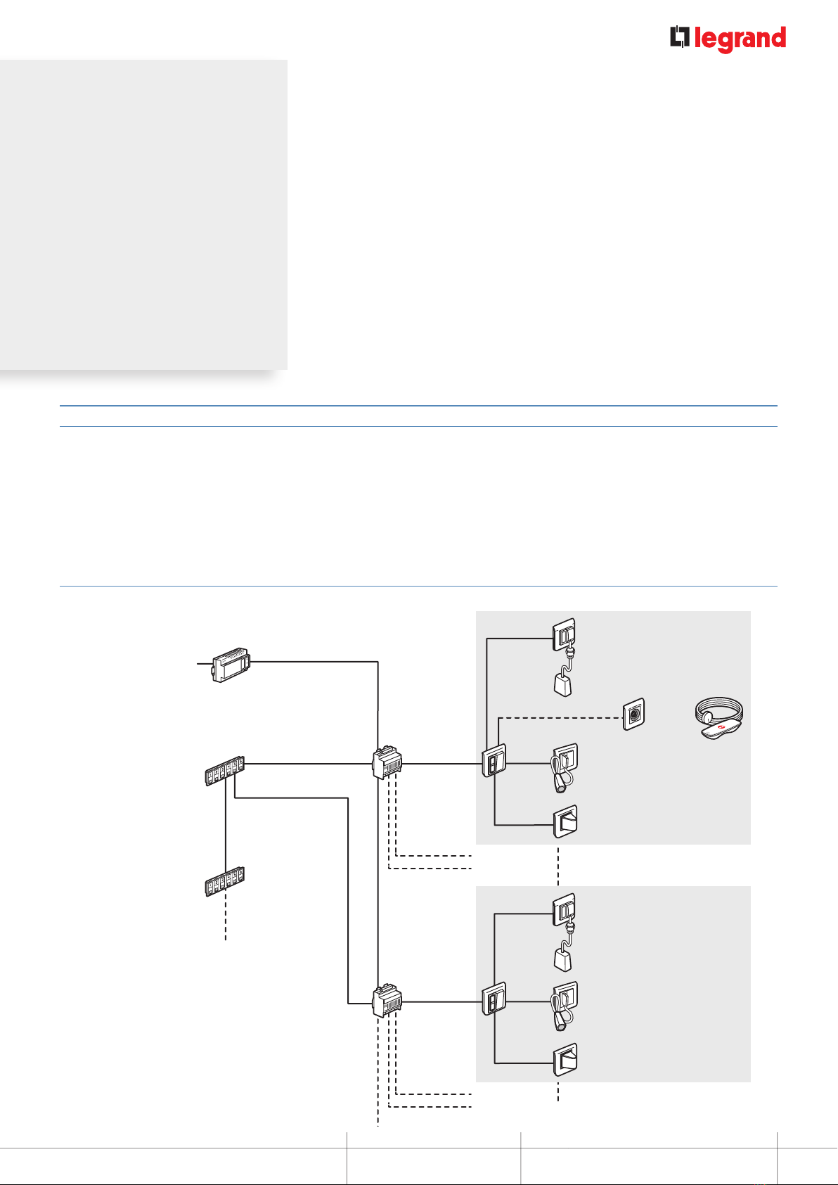
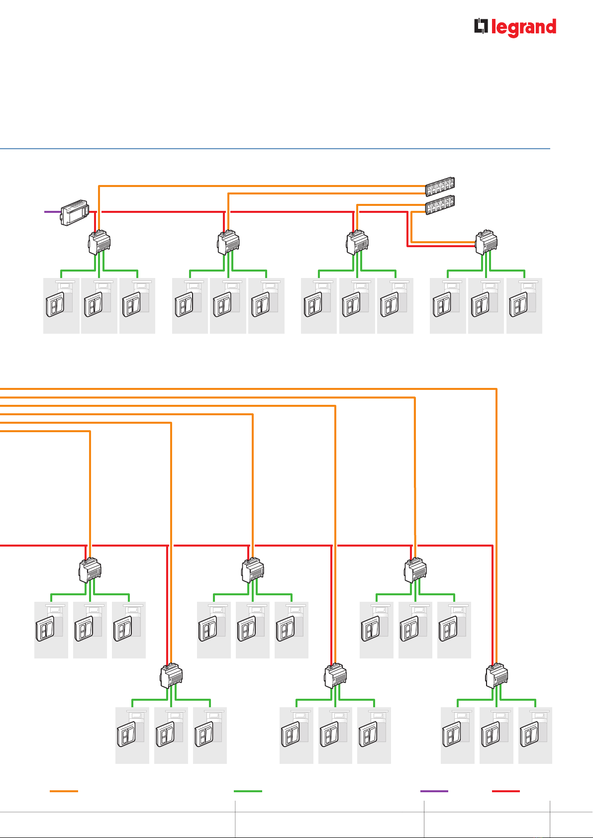
Wiring principle >>>>>>>>>>>>>>>>>>>>>>>>>>>>>>>>>>>>>>>>>>>>>>>>>>>>>>>>>3
Installation principle for a ward >>>>>>>>>>>>>>>>>>>>>>>>>>>>>>>>>>>>>>>>>>>>>>>>>>>4
Installation principle with call-forwarding over DECT and traceability on telephone coupling product (telephony package
notsupplied by Legrand) >>>>>>>>>>>>>>>>>>>>>>>>>>>>>>>>>>>>>>>>>>>>>>>>>>>>>6
Installation principle with call-forwarding over DECT and traceability on telephone coupling product and corridor display
units(telephony package not supplied by Legrand) >>>>>>>>>>>>>>>>>>>>>>>>>>>>>>>>>>>>>>>>8
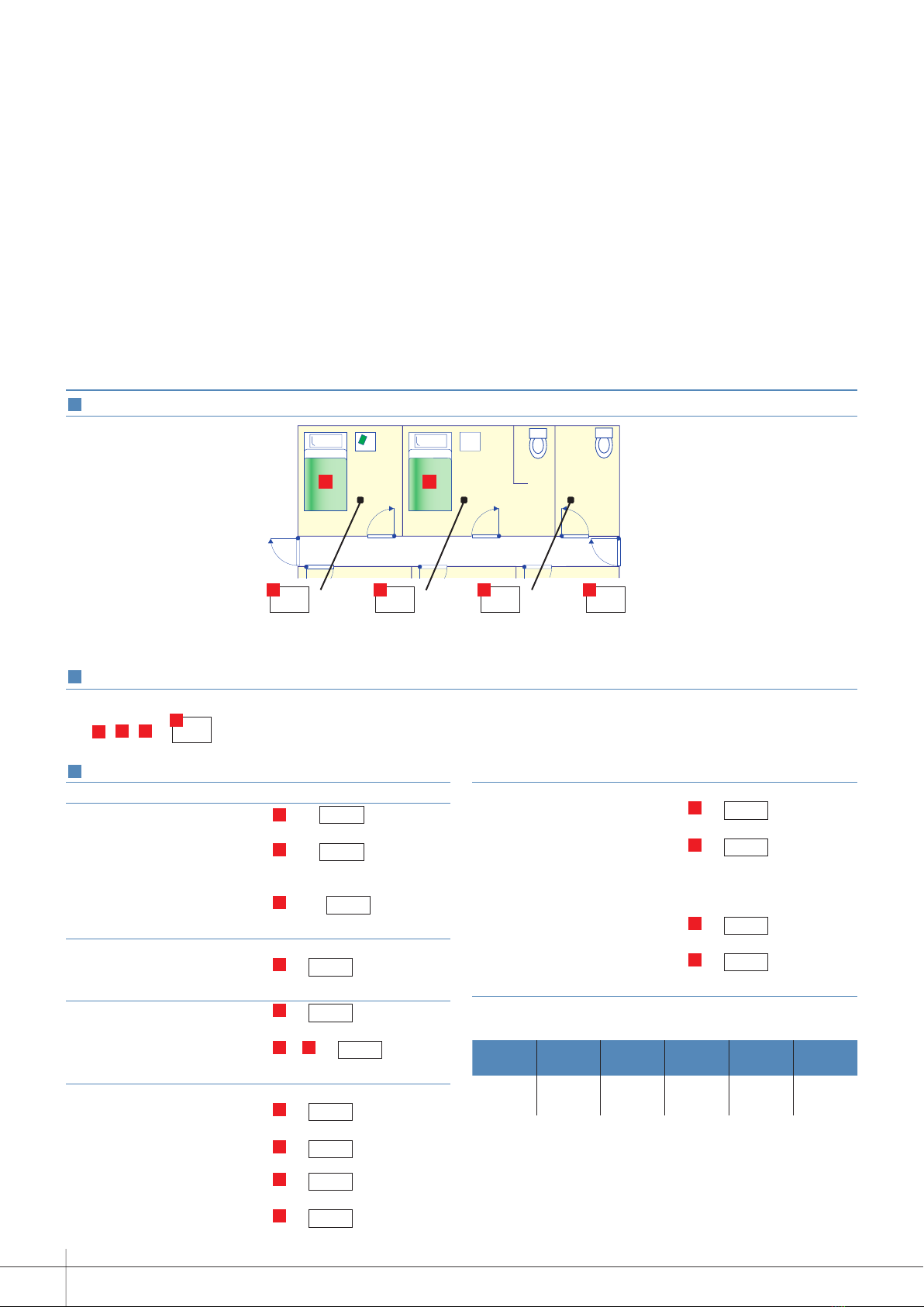
Selection guide: how to draw up your list of equipment >>>>>>>>>>>>>>>>>>>>>>>>>>>>>>>>>>>>> 10
PRESENTATION AND INSTALLATION OF DEVICES >>>>>>>>>>>>>>>>>>>>>>>>>>>>>>>>>>>>>11
0 766 60: 6-direction call display unit >>>>>>>>>>>>>>>>>>>>>>>>>>>>>>>>>>>>>>>>>>>>>>>11
0 782 12: 3-direction management module >>>>>>>>>>>>>>>>>>>>>>>>>>>>>>>>>>>>>>>>>>>>13
0 782 14: table control unit >>>>>>>>>>>>>>>>>>>>>>>>>>>>>>>>>>>>>>>>>>>>>>>>>>> 14
0 782 89/0 035 67 OR E49: power supplies >>>>>>>>>>>>>>>>>>>>>>>>>>>>>>>>>>>>>>>>>>> 14
0 782 04: door unit >>>>>>>>>>>>>>>>>>>>>>>>>>>>>>>>>>>>>>>>>>>>>>>>>>>>>>> 15
0 766 85: bathroom call units or call button >>>>>>>>>>>>>>>>>>>>>>>>>>>>>>>>>>>>>>>>>> 16
0 766 63: socket for corded push-button >>>>>>>>>>>>>>>>>>>>>>>>>>>>>>>>>>>>>>>>>>>> 17
0 783 62: corded push-button >>>>>>>>>>>>>>>>>>>>>>>>>>>>>>>>>>>>>>>>>>>>>>>>> 17
0 782 41/46: sockets for hand-held remote control units >>>>>>>>>>>>>>>>>>>>>>>>>>>>>>>>>>>> 18
0 782 45/47: sockets for hand-held remote control units >>>>>>>>>>>>>>>>>>>>>>>>>>>>>>>>>>>> 19
0 782 01/02/03: hand-held remote control units >>>>>>>>>>>>>>>>>>>>>>>>>>>>>>>>>>>>>>>> 20
0 782 43: clamp for corded push-button >>>>>>>>>>>>>>>>>>>>>>>>>>>>>>>>>>>>>>>>>>>> 21
0 783 77/78/79: remote control modules >>>>>>>>>>>>>>>>>>>>>>>>>>>>>>>>>>>>>>>>>>>>>22
0 766 64: bathroom call pull-cord (18W10) >>>>>>>>>>>>>>>>>>>>>>>>>>>>>>>>>>>>>>>>>>> 24
9 804 12: spare part for bathroom call pull-cord >>>>>>>>>>>>>>>>>>>>>>>>>>>>>>>>>>>>>>>> 24
0 766 72: double display corridor overdoor light >>>>>>>>>>>>>>>>>>>>>>>>>>>>>>>>>>>>>>>> 25
0 766 71: call transfer light for corridors >>>>>>>>>>>>>>>>>>>>>>>>>>>>>>>>>>>>>>>>>>>> 26
0 766 42: electronic buzzer >>>>>>>>>>>>>>>>>>>>>>>>>>>>>>>>>>>>>>>>>>>>>>>>>>> 26
0 771 50 + 0 782 07: biomedical call plug and socket >>>>>>>>>>>>>>>>>>>>>>>>>>>>>>>>>>>>>> 27
OPERATING MODE >>>>>>>>>>>>>>>>>>>>>>>>>>>>>>>>>>>>>>>>>>>>>>>>>>>>>>>28
Call + nurse present >>>>>>>>>>>>>>>>>>>>>>>>>>>>>>>>>>>>>>>>>>>>>>>>>>>>>> 28
Bathroom call + nurse present >>>>>>>>>>>>>>>>>>>>>>>>>>>>>>>>>>>>>>>>>>>>>>>>> 29
Call for nurse assistance (emergency) >>>>>>>>>>>>>>>>>>>>>>>>>>>>>>>>>>>>>>>>>>>>> 30
Nurse present + call from another room >>>>>>>>>>>>>>>>>>>>>>>>>>>>>>>>>>>>>>>>>>>> 31
Nurse present + call from another bathroom >>>>>>>>>>>>>>>>>>>>>>>>>>>>>>>>>>>>>>>>>> 32
Call priorities >>>>>>>>>>>>>>>>>>>>>>>>>>>>>>>>>>>>>>>>>>>>>>>>>>>>>>>>>>>33
MOSAIC NURSE CALL UNIT WIRING >>>>>>>>>>>>>>>>>>>>>>>>>>>>>>>>>>>>>>>>>>>>>34
Call + presence installation for nursing homes and residential homes for the elderly >>>>>>>>>>>>>>>>>>>>>>34
Call + presence installation with hand-hand-held remote control units and magnetic sockets >>>>>>>>>>>>>>>>> 36
Call + presence installation with call via push-button with indicator and information transfer >>>>>>>>>>>>>>>>> 38
Bed + armchair call + presence installation for nursing homes and residential homes for the elderly with DECT interface
(integrated traceability) >>>>>>>>>>>>>>>>>>>>>>>>>>>>>>>>>>>>>>>>>>>>>>>>>>>>>>40
Call + biomedical + presence installation for clinics and hospitals with corridor display units (integrated traceability) >>>>> 42
230 V cable for patient call + corridor display units and IP network cabling >>>>>>>>>>>>>>>>>>>>>>>>>>> 44
COMMISSIONING >>>>>>>>>>>>>>>>>>>>>>>>>>>>>>>>>>>>>>>>>>>>>>>>>>>>>> 46
Check before switch-on >>>>>>>>>>>>>>>>>>>>>>>>>>>>>>>>>>>>>>>>>>>>>>>>>>>> 46
Resetting the module >>>>>>>>>>>>>>>>>>>>>>>>>>>>>>>>>>>>>>>>>>>>>>>>>>>>>> 47
TROUBLESHOOTING >>>>>>>>>>>>>>>>>>>>>>>>>>>>>>>>>>>>>>>>>>>>>>>>>>>> 48

3
INSTALLATION AND USER GUIDE
MOSAIC NURSE CALL UNIT
DESCRIPTION
OF THE SYSTEM
ARCHITECTURE
Fundamental rules to follow when installing the Mosaic nurse call system
Patient call system products are associated with personal safety. They should therefore be installed by a qualified electrician, in strict
accordance with the conditions of installation and the operating instructions.
A single protection device should be installed for the entire nurse call system.
To ensure continuous operation during a mains failure, connect the system to an uninterruptible power supply (generator set and/or
inverter). If there is a mains failure longer than 1 s, all calls prior to the outage may be lost.
Note: The Mosaic nurse call system is recommended for installations with 1 to 72 directions*.
* Direction: room from which the calls originate
* 2 x 0.6 mm2pairs: 50 m max
2 x 0.9 mm2pairs: 100 m max
Between the management module and the door unit
DESCRIPTION OF THE SYSTEM ARCHITECTURE
Wiring principle
2 x 1.5 mm2
2 x 1.5 mm2
Bathroom call unit Cat. No. 0 766 64
Door unit
Cat. No.
0 782 04
230 V±
Power supply
Cat. No. 0 782 89
Management
module
Cat. No. 0 782 12
Room 1
Room 4
Room 2
Room 3
Room 5
Separate WC Room 7
6-direction display unit
Cat. No. 0 766 60
(main control unit)
6-direction display unit
Cat. No. 0 766 60
(secondary control unit)
4 control
units max.
{
2 pairs* per direction
2 pairs
6 x 0.6 mm2pairs for 3 directions
2 x 6 x 0.6 mm2
pairs for
3 directions
1 pair
2 pairs
Bathroom call unit
Cat. No. 0 766 64
Door unit
Cat. No.
0 782 04
Management
module
Cat. No. 0 782 12
1 pair
2 pairs
2 pairs
Corridor overdoor light unit
Cat. No. 0 766 72
Hand-held remote
control unit
Cat Nos. 0 782 01
or 0 782 02/03
Socket
Cat Nos. 0 782 41/46
or 0 782 45/47
Socket Cat No. 0 766 63
and corded push-button Cat No. 0 783 62
2 pairs
Corridor overdoor light unit
Cat. No. 0 766 72
Socket Cat No. 0 766 63
and corded push-button Cat No. 0 783 62

4
DESCRIPTION OF THE SYSTEM ARCHITECTURE
Power supply
Cat. No. 0 782 89
230 V
Door unit
Cat. No. 0 782 04
Door unit
Cat. No. 0 782 04
Door unit
Cat. No. 0 782 04
Room
01
Room
02
Room
03 Room
04
Room
05
Room
06
Management module
Cat. No. 0 782 12
Management module
Cat. No. 0 782 12
Door unit
Cat. No. 0 782 04
Door unit
Cat. No. 0 782 04
Door unit
Cat. No. 0 782 04
6-direction display unit
Cat. No. 0 766 60
(main control unit)
6-direction display units
Cat. No. 0 766 60 x 6 in
table control unit
Cat. No. 0 782 14 x 1
Power supply
Cat. No. 0 782 89
230 V
Management module
Cat. No. 0 782 12
Door unit
Cat. No. 0 782 04
Door unit
Cat. No. 0 782 04
Door unit
Cat. No. 0 782 04
Room
01
Room
18
Room
02
Room
03
Room
04
Room
05
Room
06
Management module
Cat. No. 0 782 12
Door unit
Cat. No. 0 782 04
Door unit
Cat. No. 0 782 04
Door unit
Cat. No. 0 782 04
Room
07
Room
08
Room
09
Room
10
Room
11
Room
12
Management module
Cat. No. 0 782 12
Door unit
Cat. No. 0 782 04
Door unit
Cat. No. 0 782 04
Door unit
Cat. No. 0 782 04
Room
13
Room
14
Room
15
Room
16
Room
17
Management module
Cat. No. 0 782 12
Door unit
Cat. No. 0 782 04
Door unit
Cat. No. 0 782 04
Door unit
Cat. No. 0 782 04
Management module
Cat. No. 0 782 12
Door unit
Cat. No. 0 782 04
Door unit
Cat. No. 0 782 04
Door unit
Cat. No. 0 782 04
Management module
Cat. No. 0 782 12
Door unit
Cat. No. 0 782 04
Door unit
Cat. No. 0 782 04
Door unit
Cat. No. 0 782 04
Management module
Cat. No. 0 782 12
Door unit
Cat. No. 0 782 04
Door unit
Cat. No. 0 782 04
Door unit
Cat. No. 0 782 04
Room
19
Room
36
Room
20
Room
21
Room
22
Room
23
Room
24
Management module
Cat. No. 0 782 12
Door unit
Cat. No. 0 782 04
Door unit
Cat. No. 0 782 04
Door unit
Cat. No. 0 782 04
Room
25
Room
26
Room
27
Room
28
Room
29
Room
30
Management module
Cat. No. 0 782 12
Door unit
Cat. No. 0 782 04
Door unit
Cat. No. 0 782 04
Door unit
Cat. No. 0 782 04
Room
31
Room
32
Room
33
Room
34
Room
35
Management module
Cat. No. 0 782 12
Door unit
Cat. No. 0 782 04
Door unit
Cat. No. 0 782 04
Door unit
Cat. No. 0 782 04
Management module
Cat. No. 0 782 12
Door unit
Cat. No. 0 782 04
Door unit
Cat. No. 0 782 04
Door unit
Cat. No. 0 782 04
Management module
Cat. No. 0 782 12
Door unit
Cat. No. 0 782 04
Door unit
Cat. No. 0 782 04
Door unit
Cat. No. 0 782 04
6 x 0.6 mm2pairs (50 m max) or 6 x 0.9 mm2pairs (100 m max) 2 x 0.6 mm2pairs (50 m max) or 2 x 0.9 mm2pairs (100 m max) 2G 1.5 mm² 2G 1.5 mm²
INSTALLATION PRINCIPLE FOR A WARD
6-room ward
36-room ward

5
MOSAIC NURSE CALL UNIT
DESCRIPTION OF THE SYSTEM ARCHITECTURE
Power supply
Cat. No. 0 782 89
230 V
Door unit
Cat. No. 0 782 04
Door unit
Cat. No. 0 782 04
Door unit
Cat. No. 0 782 04
Room
01 Room
02
Room
03 Room
04 Room
05 Room
06
Door unit
Cat. No. 0 782 04
Door unit
Cat. No. 0 782 04
Door unit
Cat. No. 0 782 04
Room
07 Room
08 Room
09 Room
10 Room
11 Room
12
Management module
Cat. No. 0 782 12 Management module
Cat. No. 0 782 12
Door unit
Cat. No. 0 782 04
Door unit
Cat. No. 0 782 04
Door unit
Cat. No. 0 782 04
Door unit
Cat. No. 0 782 04
Door unit
Cat. No. 0 782 04
Door unit
Cat. No. 0 782 04
6-direction display units
Cat. No. 0 766 60 x 2
6-direction display units
Cat. No. 0 766 60 x 6 in
table control unit
Cat. No. 0 782 14 x 1
Power supply
Cat. No. 0 782 89
230 V
Management module
Cat. No. 0 782 12
Door unit
Cat. No. 0 782 04
Door unit
Cat. No. 0 782 04
Door unit
Cat. No. 0 782 04
Room
01
Room
18
Room
02
Room
03
Room
04
Room
05
Room
06
Management module
Cat. No. 0 782 12
Door unit
Cat. No. 0 782 04
Door unit
Cat. No. 0 782 04
Door unit
Cat. No. 0 782 04
Room
07
Room
08
Room
09
Room
10
Room
11
Room
12
Management module
Cat. No. 0 782 12
Door unit
Cat. No. 0 782 04
Door unit
Cat. No. 0 782 04
Door unit
Cat. No. 0 782 04
Room
13
Room
14
Room
15
Room
16
Room
17
Management module
Cat. No. 0 782 12
Door unit
Cat. No. 0 782 04
Door unit
Cat. No. 0 782 04
Door unit
Cat. No. 0 782 04
Management module
Cat. No. 0 782 12
Door unit
Cat. No. 0 782 04
Door unit
Cat. No. 0 782 04
Door unit
Cat. No. 0 782 04
Management module
Cat. No. 0 782 12
Door unit
Cat. No. 0 782 04
Door unit
Cat. No. 0 782 04
Door unit
Cat. No. 0 782 04
Management module
Cat. No. 0 782 12
Door unit
Cat. No. 0 782 04
Door unit
Cat. No. 0 782 04
Door unit
Cat. No. 0 782 04
Room
19
Room
36
Room
20
Room
21
Room
22
Room
23
Room
24
Management module
Cat. No. 0 782 12
Door unit
Cat. No. 0 782 04
Door unit
Cat. No. 0 782 04
Door unit
Cat. No. 0 782 04
Room
25
Room
26
Room
27
Room
28
Room
29
Room
30
Management module
Cat. No. 0 782 12
Door unit
Cat. No. 0 782 04
Door unit
Cat. No. 0 782 04
Door unit
Cat. No. 0 782 04
Room
31
Room
32
Room
33
Room
34
Room
35
Management module
Cat. No. 0 782 12
Door unit
Cat. No. 0 782 04
Door unit
Cat. No. 0 782 04
Door unit
Cat. No. 0 782 04
Management module
Cat. No. 0 782 12
Door unit
Cat. No. 0 782 04
Door unit
Cat. No. 0 782 04
Door unit
Cat. No. 0 782 04
Management module
Cat. No. 0 782 12
Door unit
Cat. No. 0 782 04
Door unit
Cat. No. 0 782 04
Door unit
Cat. No. 0 782 04
6 x 0.6 mm2pairs (50 m max) or 6 x 0.9 mm2pairs (100 m max) 2 x 0.6 mm2pairs (50 m max) or 2 x 0.9 mm2pairs (100 m max) 2G 1.5 mm² 2G 1.5 mm²
12-room ward

6
DESCRIPTION OF THE SYSTEM ARCHITECTURE
Volt-free contact
interface unit
16 I/O to IP
Volt-free contact
interface unit
16 I/O to IP
Volt-free contact
interface unit
16 I/O to IP
Volt-free contact
interface unit
16 I/O to IP
Volt-free contact
interface unit
16 I/O to IP
Volt-free contact
interface unit
16 I/O to IP
Volt-free contact
interface unit
16 I/O to IP
Volt-free contact
interface unit
16 I/O to IP
Vl
tf
tt
Volt-free contact
interface unit
16 I/O to IP
Volt-free contact
interface unit
16 I/O to IP
Traceability on standard computer with icon
congured as a xed IP address.
For use by:
- Nurses
- Maintenance
- Management
Congured by the network integrator.
Management module Cat. No. 0 782 12
9-room Neurology ward
Riser
VDI package
ELV equipment room
Autocom cabinet
Main cross-connect
cabinet
Telephone
coupler with
xed IP address
3rd oor
2nd oor
1st oor
Management module Cat. No. 0 782 12
Nurse call package
9-room Ophthalmology ward
Management module Cat. No. 0 782 12
Nurse call package
18-room Dermatology ward
Management module Cat. No. 0 782 12
Nurse call package
36-room Urology ward
Management module Cat. No. 0 782 12
Nurse call package
30-room General surgery department
Nurse call package
12-room Cardiology ward
Management module Cat. No. 0 782 12
Nurse call package
Telephony packageTelephony package
UTP/FTP cable Cat. 5e minimum
PABX/IPBX
RS232
DECT
TERMINAL
DECT
TERMINAL
DECT
TERMINAL
Cables with 2 x 0.6 mm2pairs (50 m max) or 0.9 mm2pairs (100 m max)
*Répartiteur Général Informatique (main cross-connect)
90 m max.
90 m max.
INSTALLATION PRINCIPLE WITH CALLFORWARDING OVER DECT AND TRACEABILITY ON TELEPHONE COUPLING PRODUCT TELEPHONY PACKAGE NOT SUPPLIED BY LEGRAND

7
MOSAIC NURSE CALL UNIT
DESCRIPTION OF THE SYSTEM ARCHITECTURE
Volt-free contact
interface unit
16 I/O to IP
Volt-free contact
interface unit
16 I/O to IP
Volt-free contact
interface unit
16 I/O to IP
Volt-free contact
interface unit
16 I/O to IP
Volt-free contact
interface unit
16 I/O to IP
Volt-free contact
interface unit
16 I/O to IP
Volt-free contact
interface unit
16 I/O to IP
Volt-free contact
interface unit
16 I/O to IP
Vl
tf
tt
Volt-free contact
interface unit
16 I/O to IP
Volt-free contact
interface unit
16 I/O to IP
Traceability on standard computer with icon
congured as a xed IP address.
For use by:
- Nurses
- Maintenance
- Management
Congured by the network integrator.
Management module Cat. No. 0 782 12
9-room Neurology ward
Riser
VDI package
ELV equipment room
Autocom cabinet
Main cross-connect
cabinet
Telephone
coupler with
xed IP address
3rd oor
2nd oor
1st oor
Management module Cat. No. 0 782 12
Nurse call package
9-room Ophthalmology ward
Management module Cat. No. 0 782 12
Nurse call package
18-room Dermatology ward
Management module Cat. No. 0 782 12
Nurse call package
36-room Urology ward
Management module Cat. No. 0 782 12
Nurse call package
30-room General surgery department
Nurse call package
12-room Cardiology ward
Management module Cat. No. 0 782 12
Nurse call package
Telephony packageTelephony package
UTP/FTP cable Cat. 5e minimum
PABX/IPBX
RS232
DECT
TERMINAL
DECT
TERMINAL
DECT
TERMINAL
Cables with 2 x 0.6 mm2pairs (50 m max) or 0.9 mm2pairs (100 m max)
*Répartiteur Général Informatique (main cross-connect)
90 m max.
90 m max.
INSTALLATION PRINCIPLE WITH CALLFORWARDING OVER DECT AND TRACEABILITY ON TELEPHONE COUPLING PRODUCT TELEPHONY PACKAGE NOT SUPPLIED BY LEGRAND

8
DESCRIPTION OF THE SYSTEM ARCHITECTURE
Telephony package
Volt-free contact
interface unit
16 I/O to IP
Volt-free contact
interface unit
16 I/O to IP
Volt-free contact
interface unit
16 I/O to IP
Volt-free contact
interface unit
16 I/O to IP
Volt-free contact
interface unit
16 I/O to IP
Volt-free contact
interface unit
16 I/O to IP
Volt-free contact
interface unit
16 I/O to IP
Volt-free contact
interface unit
16 I/O to IP
Volt-free contact
interface unit
16 I/O to IP
Volt-free contact
interface unit
16 I/O to IP
230 V
or PoE
230 V
or PoE
230 V
or PoE
230 V
or PoE
Management module Cat. No. 0 782 12
9-room Neurology ward
Riser
VDI package
ELV equipment room
Main cross-connect
cabinet
3rd oor
2nd oor
1st oor
Management module Cat. No. 0 782 12
Nurse call package
9-room Ophthalmology ward
Management module Cat. No. 0 782 12
Nurse call package
18-room Dermatology ward
Management module Cat. No. 0 782 12
Nurse call package
36-room Urology ward
Management module Cat. No. 0 782 12
Nurse call package
30-room General surgery department
Nurse call package
12-room Cardiology ward
Management module Cat. No. 0 782 12
Nurse call package
Telephony package
UTP/FTP cable Cat. 5e minimum
RS232
DECT
TERMINAL
DECT
TERMINAL
DECT
TERMINAL
Cables with 2 x 0.6 mm2pairs (50 m max) or 0.9 mm2pairs (100 m max)
*Répartiteur Général Informatique (main cross-connect)
23
o
r
2
o
r
2
o
r
V
o
E
90 m max.
90 m max.
Autocom cabinet
PABX/IPBX
Traceability on standard computer with icon
congured as a xed IP address.
For use by:
- Nurses
- Maintenance
- Management
Congured by the network integrator.
Telephone
coupler with
xed IP address
INSTALLATION PRINCIPLE WITH CALLFORWARDING OVER DECT AND TRACEABILITY ON TELEPHONE COUPLING PRODUCT AND CORRIDOR DISPLAY UNITS TELEPHONY PACKAGE NOT SUPPLIED BY LEGRAND

9
PRESENTATION AND INSTALLATION OF DEVICES MOSAIC NURSE CALL UNIT
Telephony package
Volt-free contact
interface unit
16 I/O to IP
Volt-free contact
interface unit
16 I/O to IP
Volt-free contact
interface unit
16 I/O to IP
Volt-free contact
interface unit
16 I/O to IP
Volt-free contact
interface unit
16 I/O to IP
Volt-free contact
interface unit
16 I/O to IP
Volt-free contact
interface unit
16 I/O to IP
Volt-free contact
interface unit
16 I/O to IP
Volt-free contact
interface unit
16 I/O to IP
Volt-free contact
interface unit
16 I/O to IP
230 V
or PoE
230 V
or PoE
230 V
or PoE
230 V
or PoE
Management module Cat. No. 0 782 12
9-room Neurology ward
Riser
VDI package
ELV equipment room
Main cross-connect
cabinet
3rd oor
2nd oor
1st oor
Management module Cat. No. 0 782 12
Nurse call package
9-room Ophthalmology ward
Management module Cat. No. 0 782 12
Nurse call package
18-room Dermatology ward
Management module Cat. No. 0 782 12
Nurse call package
36-room Urology ward
Management module Cat. No. 0 782 12
Nurse call package
30-room General surgery department
Nurse call package
12-room Cardiology ward
Management module Cat. No. 0 782 12
Nurse call package
Telephony package
UTP/FTP cable Cat. 5e minimum
RS232
DECT
TERMINAL
DECT
TERMINAL
DECT
TERMINAL
Cables with 2 x 0.6 mm2pairs (50 m max) or 0.9 mm2pairs (100 m max)
*Répartiteur Général Informatique (main cross-connect)
23
o
r
2
o
r
2
o
r
V
o
E
90 m max.
90 m max.
Autocom cabinet
PABX/IPBX
Traceability on standard computer with icon
congured as a xed IP address.
For use by:
- Nurses
- Maintenance
- Management
Congured by the network integrator.
Telephone
coupler with
xed IP address
INSTALLATION PRINCIPLE WITH CALLFORWARDING OVER DECT AND TRACEABILITY ON TELEPHONE COUPLING PRODUCT AND CORRIDOR DISPLAY UNITS TELEPHONY PACKAGE NOT SUPPLIED BY LEGRAND

10
SELECTION GUIDE: HOW TO DRAW UP YOUR LIST OF EQUIPMENT
Gather the following information
1
Calculate the number of directions
To determine the number of directions, simply add:
2
3
Number of
separate
rooms
Number
of rooms
with WC
Number of
separate WCs
Number
of beds
DD
A B C D
DD
E
+ + =
B C
A
Draw up your list of equipment
Nurses' station and management equipment
Display unit Cat. No. 0 766 60 = E/6 or display units
Management module
Cat. No. 0 782 12 = E/3 or modules
Option:
Table control unit
Cat. No. 0 782 14 = E/36 or control units
Corridor equipment
Corridor overdoor light units
Cat. No. 0 766 72 = Eor overdoor lights
Room/bathroom equipment
Door unit Cat. No. 0 782 04 = Eor door units
Bathroom call unit
Cat. No. 0 766 64 = B+ Cor call units
Bed equipment
Socket for corded push-button
Cat. No. 0 766 63 = Dor sockets
Corded push-button
Cat. No. 0 783 62 = Dor corded buttons
OR
Magnetic socket Cat. No. 0 782 46 = Dor sockets
Hand-held remote control unit
for call only Cat. No. 0 782 01 = Dor hand-held
remote
control units
Bed equipment (continued)
OR
Magnetic socket Cat. No. 0 782 47 = Dor sockets
Hand-held remote control unit for
call only Cat. Nos. 0 782 02/03 = Dor hand-held
remote
control units
Option:
Shunt plug for biomedical
alarm Cat. No. 0 782 07 = Dor plugs
Socket for biomedical alarm
Cat. No. 0 771 50 = Dor sockets
Power supply:
Power supply Cat. No. 0 782 89
Number of power supplies to be calculated using the table below
0 782 04 0 766 72 0 766 64 0 782 01/
02/03
0 782 12 0 766 60
0.7 W 0.9 W 0.7 W 0.8 W 1 W 0.4 W per
direction
Recommendation: 1 power supply for 36 directions (corresponds to 30% of
simultaneous calls max.)
DESCRIPTION OF THE SYSTEM ARCHITECTURE

11
PRESENTATION AND INSTALLATION OF DEVICES MOSAIC NURSE CALL UNIT
PRESENTATION AND
INSTALLATION
OF DEVICES
1- Management module terminals
2- Room 6 terminals
3- Room 1 terminals
4- Room 2 terminals
5- Room 3 terminals
6- Room 4 terminals
7- Room 5 terminals
0 766 60
1 2
34 5 6 7
Technical characteristics
nPower supply: 24 V=
nConsumption: min. 0.4 W - max. 2.8 W
nOperating temperature: 5 to 40°C
nStorage temperature: -20 to 70°C
nProtection index: IP40
nDimensions: 135 x 22.5 mm
nInstallation:
- On table control unit Cat. No. 0 782 14
- Flush-mounted in box depth 50 mm Cat. No. 0 800 53
- Surface-mounted in box depth 40 mm Cat. No. 0 802 86
nSound level:
- 65 dB (A) at 1 m placed on table
- 75 dB (A) fixed to wall 1.60 m off the floor
- 62 dB (A) at 1 m placed on table
- 72 dB (A) fixed to wall 1.60 m off the floor
ConnectionPerforms the main and secondary display functions.
Main display unit: used to monitor rooms in the ward from the
nurses' station.
Secondary display unit: used to transfer information from the
main display unit. 4 secondary display units max.
Indicates calls by lighting up numbered indicator lights and
generating an audible signal.
Can indicate several calls simultaneously.
Displays the call and nurse presence
and mute setting.
Calls can be transferred to 4 other display units (treatment room,
rest area, etc).
Supplied without plate.
Supplied with sheets of numbered stickers from 1 to 99.
0 766 60: 6DIRECTION* CALL DISPLAY UNIT
Direction
identification*
Mute button
Identification
labelssupplied
* Direction: room from which the calls originate

12
PRESENTATION AND INSTALLATION OF DEVICES
Cat. No. 0 800 53 Cat. No. 0 801 26
Cat. No. 0 802 76
Cat. No. 0 802 53 Cat. No. 0 802 66
Cat. No. 0 802 66
Cat. No. 0 766 60
Cat. No. 0 766 60
Cat. No. 0 802 53
Cat. No. 0 788 16
Cat. No. 0 788 16
Cat. No. 0 766 60
Cat. No. 0 788 36
Cat. No. 0 788 36
Cat. No. 0 766 60
Cat. No. 0 802 86
Flush-mounted wall installation Flush-mounted 2-gang wall installation
Surface-mounted 2-gang wall installation
Surface-mounted wall installation
* Direction: room from which the calls originate
0 766 60: 6DIRECTION* CALL DISPLAY UNIT CONTINUED

13
PRESENTATION AND INSTALLATION OF DEVICES MOSAIC NURSE CALL UNIT
0 782 12: 3DIRECTION MANAGEMENT MODULE*
Technical characteristics
nPower supply: 24 V=
nConsumption (min): 39 mA
(max): 300 mA
nOperating temperature: 5 to 40°C
nStorage temperature: -20 to 70°C
nSize: 4 DIN modules
ConnectionManages 3 directions.
Option of forwarding:
- for indicator
- for buzzer via a solid state relay
- to DECT, via a telephone coupling product
- to master indicator (lights up if the indicator on at least one of
the 3 directions is lit up).
1- 24 V= power supply terminals
2- Master indicator or solid state relay
terminals
3- Call display unit terminals
4- Door unit direction 1
5- Door unit direction 2
6- Door unit direction 3
7- Volt-free contact for DECT call
forwarding or indicator or buzzer
3
4567
1
2
* Direction: room from which the calls originate
Max : 24 V 0,5 A
nContact beat frequency
Normal call (0.5 Hz)
Emergency call (1 Hz)

14
Technical characteristics
nSupply voltage: 230 VA+10% - 50/60 Hz
nOutput voltage: 24 V=
nMax. current: 2 A
nMax. power: 48 W
nOperating temperature: 5 to 40°C
nStorage temperature: -20 to 70°C
nProtection index: IP30
nSize: 6 DIN modules
Cat. No. 0 782 09: Powers the system with SELV.
Recommendation: 1 power supply for 36 directions (corresponds
to 30% of simultaneous calls max.).
0 782 89/0 035 67 OR E49: POWER SUPPLIES
Cat. No. 0 035 67 or E49: Powers the solid state relay for
information transfer (indicator or buzzer).
Technical characteristics
nSupply voltage: 230VA
nBUS output voltage: 27 V=
nMax. BUS current: 600 mA
nMax. power: 21.5 W
nMax. consumption: 26.8 W
nOperating temperature: 5 to 40°C
nStorage temperature: -20 to 70°C
nProtection index: IP20
nSize: 2 DIN modules
PRESENTATION AND INSTALLATION OF DEVICES
0 782 14: TABLE CONTROL UNIT
Technical characteristics
nProtection index: IP 40 with blanking plates
nDimensions: 310 x 295 x 75 mm (36 modules)
Support frame which can take up to 6 display units
Cat.No.076660.
Makes it easier to run cables when installing several display units.
Fit blanking plates over unused positions.
Installation
Cat. No. 0 770 71

15
PRESENTATION AND INSTALLATION OF DEVICES MOSAIC NURSE CALL UNIT
Antimicrobial
Antimicrobial
R
W
0 782 04: DOOR UNIT
R - Red LED indicator
W - White LED indicator
- Bathroom or biomedical pull cord
- Corded push-button or hand-held remote control
- Door unit
Technical characteristics
nPower supply: via management module Cat. No. 0 782 12
nOperating temperature: 5 to 40°C
nStorage temperature: -20 to 70°C
nAntimicrobial
nProtection index: IP20
nDimensions (H x W x D): 82 x 82 x 43 mm
nInstallation:
- in 1-gang (2 modules) flush-mounting box Cat. No. 0 800 41
or Cat. No. 0 801 41 (concrete)
- in surface-mounting box Cat. No. 0 802 81 (IP 20)
nLED indicators with resistor in parallel:
- Impedance: 1 kΩ
- DC voltage: 9 to 31 V
Connection (from 15W22)
Flush-mounted wall installation
Surface-mounted wall installation
Consisting of 2 white indicators to be covered with stickers (red,
green, orange or blue) and a push-button for acknowledging the
call and nurse presence.
Recommendation: Place the red sticker over the call indicator
(top indicator).
Cat. No. 0 800 41
Cat. No. 0 801 41
Door unit
Cat. No. 0 782 04
Management
module
Cat. No. 0 782 12
Not used

16
R
W
R
R
W
R
0 766 85: BATHROOM CALL UNITS OR CALL BUTTON
Technical characteristics
nPower supply: via management module Cat. No. 0 782 12
nOperating temperature: 5 to 40°C
nStorage temperature: -20 to 70°C
nAntimicrobial
nProtection index: IP20
nDimensions (H x W x D): 82 x 82 x 43 mm
nInstallation:
- in 1-gang (2 modules) flush-mounting box Cat. No. 0 800 41 or
Cat. No. 0 801 41 (concrete)
- in surface-mounting box Cat. No. 0 802 81 (IP 20)
Recommendation: Place the red sticker over the call indicator (top
indicator).
Bathroom call button connection (from 15W22)
Bedroom call button connection (from 15W22)
Flush-mounted wall installation
Surface-mounted wall installation
Cat. No. 0 800 41
Cat. No. 0 801 41
Antimicrobial
Antimicrobial
PRESENTATION AND INSTALLATION OF DEVICES
Door unit
Cat. No. 0 782 04
Bathroom call
button
Cat. No. 0 766 85
Bedroom call
button
Cat. No. 0 766 85
Door unit
Cat. No. 0 782 04
R - Red LED indicator
W - White LED indicator
R - Red LED indicator
W - White LED indicator
Not used

17
PRESENTATION AND INSTALLATION OF DEVICES MOSAIC NURSE CALL UNIT
0 766 63: SOCKET FOR CORDED PUSHBUTTON
Technical characteristics
nPower supply: via management module Cat. No. 0 782 12
nOperating temperature: 5 to 40°C
nStorage temperature: -20 to 70°C
nProtection index: IP20
nDimensions: 82 x 82 x 36 mm
nInstallation:
- in 1-gang (2 modules) flush-mounting box Cat. No. 0 800 41 or
Cat. No. 0 801 41 (concrete)
- on the wall with surface-mounting box Cat. No. 0 802 81
n12 mm fixing centres
Technical characteristics
nPower supply: via socket for corded push-button
nOperating temperature: 5 to 40°C
nStorage temperature: -20 to 70°C
nProtection index: IP20
nCord length: 2 m
nEjectable from 45° angle
nFactory-fitted NC contact.
NO contact possible by replacing the brown wire in the plug with
the black wire.
Connection
Socket for corded push-button or biomedical alarm.
Supplied on 2-module plate with blanking plate.
Allows patients to call a nurse via the door unit.
For use in conjunction with socket Cat. No. 0 766 63.
With 12 mm fixing centre plug for 2P socket Cat. No. 0 771 50.
Socket for
corded push-
button
Cat. No. 0 766 63
0 783 62: CORDED PUSHBUTTON
R
W
Conductor marking
Closed in rest mode
Factory wiring
Connect
blue and
brown
Door unit
Cat. No. 0 782 04
R - Red LED indicator
W - White LED indicator

18
PRESENTATION AND INSTALLATION OF DEVICES
0 782 41/46: SOCKETS FOR HANDHELD REMOTE CONTROL UNITS
Technical characteristics
nPower supply: via the door unit
nOperating temperature: 5 to 40°C
nStorage temperature: -20 to 70°C
nAntimicrobial
nProtection index: IP40
nDimensions:
- Cat. No. 0 782 41: 45 x 45 x 36 mm
- Cat. No. 0 782 46: 82 x 82 x 36 mm
nInstallation:
- in 1-gang flush-mounting box (2 modules)
- on wall with surface-mounting box Cat. No. 0 802 81
- in a strip using special holder supplied
• Connection
Example: 1 bed in a room.
• Flush-mounted wall installation with 1-gang
flush-mounting box
• Surface-mounted wall installation with box Cat. No. 0 802 81
Sockets Cat. No. 0 782 41 for mounting in a strip and 0 782 46 for
call-only hand-held remote control unit.
Magnetic connection between hand-held unit and socket: can be
ejected in any direction with pull-out force designed to avoid any
damage to the equipment.
Antimicrobial.
Non-indexed magnetic connection socket for hand-held remote
control unit Cat. No. 0 782 01.
0 782 41
0 782 46
0 782 01
R
W
1234
+-
Door unit
Cat. No. 0 782 04
Hand-held unit
socket
Cat. No. 0 782 46
R - Red LED indicator
W - White LED indicator

19
PRESENTATION AND INSTALLATION OF DEVICES MOSAIC NURSE CALL UNIT
0 782 45/47: SOCKETS FOR HANDHELD REMOTE CONTROL UNITS
Technical characteristics
nPower supply:
- via the door unit for nurse calls
- via remote control module Cat. No. 0 783 77 or 0 783 78 or 0
783 79 for lighting and roller blinds
nOperating temperature: 5 to 40°C
nStorage temperature: -20 to 70°C
nAntimicrobial
nProtection index: IP40
nDimensions:
- Cat. No. 0 782 45: 45 x 45 x 36 mm
- Cat. No. 0 782 47: 82 x 82 x 36 mm
nInstallation:
- in 1-gang flush-mounting box (2 modules)
- on wall with surface-mounting box Cat. No. 0 802 81
Connection
Example: 1 bed in a room.
Flush-mounted wall installation with 1-gang flush-
mountingbox
Surface-mounted wall installation with box Cat. No. 0 802 81
Sockets Cat. Nos. 0 782 45 and 0 782 47 for hand-held remote
control units for calls and controls.
Magnetic connection between hand-held unit and socket: can be
ejected in any direction with pull-out force designed to avoid any
damage to the equipment.
Antimicrobial.
Indexed magnetic connection socket for hand-held remote control
unit Cat. Nos. 0 782 02 and 782 03.
R
W
12 11 10 987
123456
+-
0 782 47
0 782 45
0 782 03
0 782 02
Hand-held unit
socket
Cat. No. 0 782 47
Door unit
Cat. No. 0 782 04
R - Red LED indicator
W - White LED indicator

20
1234
24 V
+ –
PRESENTATION AND INSTALLATION OF DEVICES
0 782 01/02/03: HANDHELD REMOTE CONTROL UNITS
Hand-held remote control unit for calls and controls
Cat. No. 0 782 02
For use with socket Cat. No. 0 782 45 or 0 782 47.
Hand-held remote control unit for call only (corded push-button)
Cat. No. 0 782 01
For use with socket Cat. No. 0 782 41 or 0 782 46.
Connection
Allow patients to call a nurse (using an NC push-button with call
confirmation indicator) via the door unit.
Magnetic connection between hand-held units and sockets: can
be ejected in any direction with pull-out force designed to avoid
any damage to the equipment.
These products are compatible with other nurse call systems with
an NC (Normally Closed) contact on 2 terminals and LED call
confirmation indicator on 2 terminals.
Recommended cleaning: use wipes impregnated with detergent
for food contact surfaces (Dettol, etc).
1- Nurse call button
2- Reading light control (NO push-button)
3- Room lighting control (NO push-button)
2.50 m cord
0 782 01
0 782 41/46
0 782 01
Nurse call
button
3
1
2
Red call confirmation
indicator
Red call confirmation
indicator
Hand-held remote control unit for calls and controls
Cat. No. 0 782 03
For use with socket Cat. No. 0 782 45 or 0 782 47.
1- Nurse call button
2- Reading light control (NO push-button)
3- Room lighting control (NO push-button)
4- Red call confirmation indicator
5 and 6- Roller blind control (NO push-button)
7- Free function button (NO push-button)
6
2
3
1
5
7
4
Other manuals for MOSAIC Series
1
This manual suits for next models
27
Table of contents
Other LEGRAND Medical Equipment manuals
Popular Medical Equipment manuals by other brands

Integra
Integra MAYFIELD A1108 instruction manual

Stryker
Stryker System 8 8203-026-000 Instructions for use

Braun
Braun Aesculap Neurosurgery Instructions for use/Technical description

Beckman Coulter
Beckman Coulter UniCel DxC 660i Training manual

Lloyd
Lloyd GALAXY 900HS Operation manual

KCI
KCI V.A.C.Via Instructions for use