manuals.online logo
Brands
  1. Home
  2. •
  3. Brands
  4. •
  5. LEGRAND
  6. •
  7. Switch
  8. •
  9. LEGRAND Whad 5-6 kVA User manual

LEGRAND Whad 5-6 kVA User manual

This manual suits for next models

2

Other LEGRAND Switch manuals

LEGRAND In One Celiane 672 56 User manual

LEGRAND

LEGRAND In One Celiane 672 56 User manual

LEGRAND Excel Life EM883 User manual

LEGRAND

LEGRAND Excel Life EM883 User manual

LEGRAND Niloe 7 64X 71 User manual

LEGRAND

LEGRAND Niloe 7 64X 71 User manual

LEGRAND Arteor 5 722 69 User manual

LEGRAND

LEGRAND Arteor 5 722 69 User manual

LEGRAND In One 882 10 User manual

LEGRAND

LEGRAND In One 882 10 User manual

LEGRAND In One Mosaic 916 19 User manual

LEGRAND

LEGRAND In One Mosaic 916 19 User manual

LEGRAND Niloe LE-764500 User manual

LEGRAND

LEGRAND Niloe LE-764500 User manual

LEGRAND 0 676 94 User manual

LEGRAND

LEGRAND 0 676 94 User manual

LEGRAND 2500 W RF User manual

LEGRAND

LEGRAND 2500 W RF User manual

LEGRAND Wattstopper LMSW-101 User manual

LEGRAND

LEGRAND Wattstopper LMSW-101 User manual

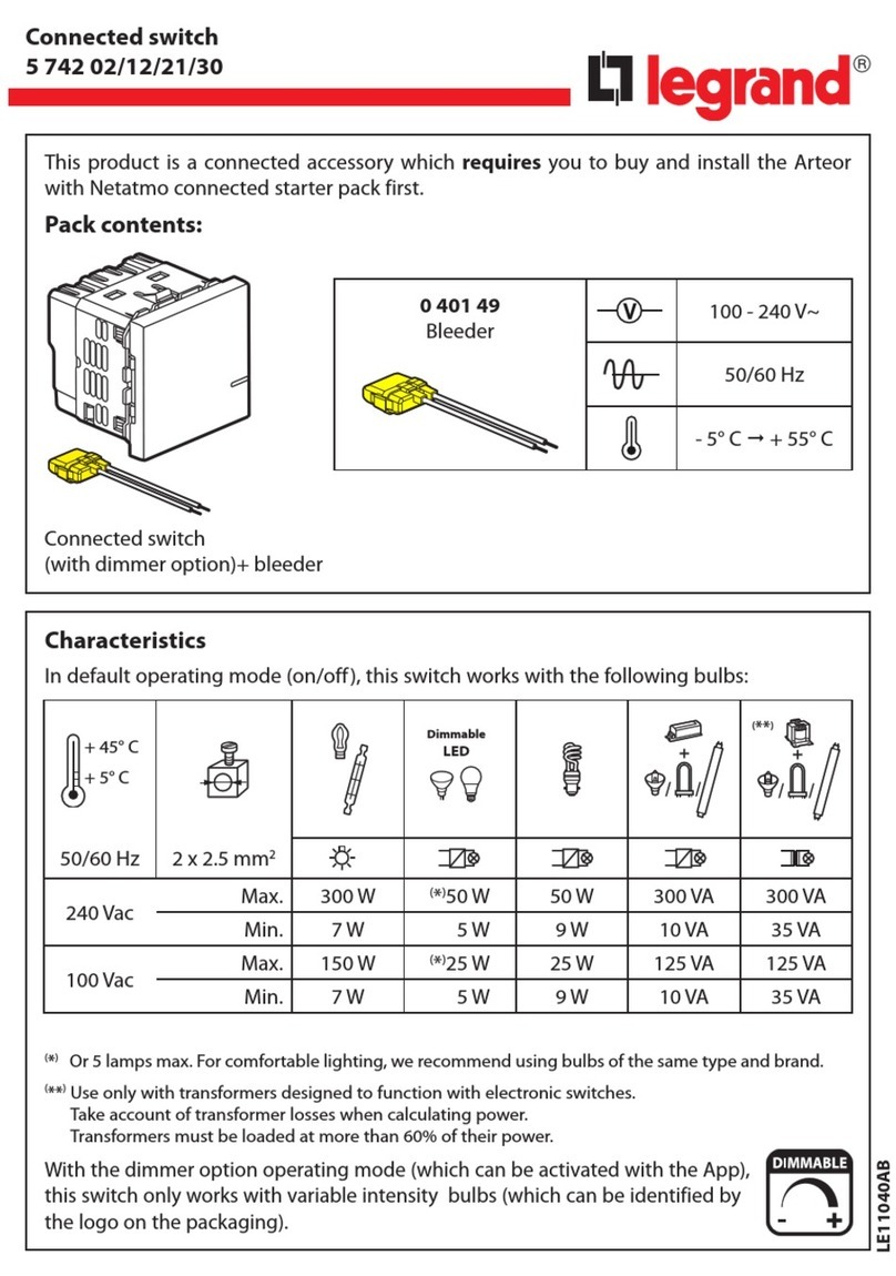
LEGRAND 5 742 02 User manual

LEGRAND

LEGRAND 5 742 02 User manual

LEGRAND Luxul SW-510-48P-F User manual

LEGRAND

LEGRAND Luxul SW-510-48P-F User manual

LEGRAND Wattstopper HDLS1SS User manual

LEGRAND

LEGRAND Wattstopper HDLS1SS User manual

LEGRAND Mosaic Manageable switch Operator's manual

LEGRAND

LEGRAND Mosaic Manageable switch Operator's manual

LEGRAND Soliroc 778 51 User manual

LEGRAND

LEGRAND Soliroc 778 51 User manual

LEGRAND 672 63 User manual

LEGRAND

LEGRAND 672 63 User manual

LEGRAND Mosaic 0 766 60 User manual

LEGRAND

LEGRAND Mosaic 0 766 60 User manual

LEGRAND PRO 21 7756 36 User manual

LEGRAND

LEGRAND PRO 21 7756 36 User manual

LEGRAND PRO 21 7756 16 User manual

LEGRAND

LEGRAND PRO 21 7756 16 User manual

LEGRAND adorne sofTap Dimmer ADTP600RMH User manual

LEGRAND

LEGRAND adorne sofTap Dimmer ADTP600RMH User manual

LEGRAND Galion 2 824 26 User manual

LEGRAND

LEGRAND Galion 2 824 26 User manual

LEGRAND Arteor 5 7 Series User manual

LEGRAND

LEGRAND Arteor 5 7 Series User manual

LEGRAND 496 05 User manual

LEGRAND

LEGRAND 496 05 User manual

LEGRAND Wattstopper LMDM-101-B User manual

LEGRAND

LEGRAND Wattstopper LMDM-101-B User manual

Popular Switch manuals by other brands

SMC Networks SMC6224M Technical specifications

SMC Networks

SMC Networks SMC6224M Technical specifications

Aeotec ZWA003-S operating manual

Aeotec

Aeotec ZWA003-S operating manual

TRENDnet TK-209i Quick installation guide

TRENDnet

TRENDnet TK-209i Quick installation guide

Planet FGSW-2022VHP user manual

Planet

Planet FGSW-2022VHP user manual

Avocent AutoView 2000  AV2000BC AV2000BC Installer/user guide

Avocent

Avocent AutoView 2000 AV2000BC AV2000BC Installer/user guide

Moxa Technologies PT-7728 Series user manual

Moxa Technologies

Moxa Technologies PT-7728 Series user manual

Intos Electronic inLine 35392I operating instructions

Intos Electronic

Intos Electronic inLine 35392I operating instructions

Cisco Catalyst 3560-X-24T Technical specifications

Cisco

Cisco Catalyst 3560-X-24T Technical specifications

Asante IntraCore IC3648 Specifications

Asante

Asante IntraCore IC3648 Specifications

Siemens SIRIUS 3SE7310-1AE Series Original operating instructions

Siemens

Siemens SIRIUS 3SE7310-1AE Series Original operating instructions

Edge-Core DCS520 quick start guide

Edge-Core

Edge-Core DCS520 quick start guide

RGBLE S00203 user manual

RGBLE

RGBLE S00203 user manual

Thrustmaster FLIGHT SIMULATOR X quick guide

Thrustmaster

Thrustmaster FLIGHT SIMULATOR X quick guide

Southwire SURGE GUARD 41390 RVC troubleshooting guide

Southwire

Southwire SURGE GUARD 41390 RVC troubleshooting guide

Buhler Nivotemp NT 61 Brief instructions

Buhler

Buhler Nivotemp NT 61 Brief instructions

Kramer VS-41HDCP user manual

Kramer

Kramer VS-41HDCP user manual

Techly IDATA AU-270 user manual

Techly

Techly IDATA AU-270 user manual

Belkin F1U109 user manual

Belkin

Belkin F1U109 user manual

manuals.online logo
manuals.online logoBrands
  • About & Mission
  • Contact us
  • Privacy Policy
  • Terms and Conditions

Copyright 2025 Manuals.Online. All Rights Reserved.

The manual bypass enables the disconnection and reconnection of the
UPS to the protected load without any interruption of the power supply.
It is possible therefore to service the UPS with no downtime and
therefore without causing any inconvenience to the user.
• Box contents:
1 pcs Manual by pass
1 Instructions
2 pcs self threading screws 2.9 x 9.5
2 pcs screws 2.9 x 9.5
1 pcs protection panel
• Installation:
The manual bypass must be installed by qualified personnel.
1) Switch off the UPS
2) Disconnect the UPS input cable from the mains supply and the
UPS output cable from the load
3) Unscrew the 2 fixing screws and remove the I/O connections box
on the rear of the UPS
4) Unwire the two cables from the I/O plug: they are used to connect
the UPS to the bypass
5) Connect the input wire and the output wire to the connector taking
care to to respect the indications re. IN/OUT, phase and neutral,
and then tighten the cable guide ring nuts.
6) Fix the protection panel and fix with the self threading screws
provided
7) Install the bypass onto the UPS by inserting it in the UPS socket
and fixing it with the two M4x70 screws which were removed
previously and 2,9x9,5 screws.
Il by-pass di servizio permette di scollegare e riconnettere l’UPS
all’utilizzo senza interruzioni di alimentazione; è così possibile
fare manutenzione all’UPS senza disagi per l’utente.
• Contenuto dell’imballo:
n. 1 Centrale by-pass
n. 1 Foglio istruzioni
n. 2 viti autofilettanti 2,9 x 9,5
n. 2 viti 2,9 x 9,5
n. 1 pannello di protezione
• Installazione:
L’installazione deve essere eseguita da personale tecnico qualificato.
1) Spegnere l’UPS a cui si vuole collegare il by-pass.
2) Scollegare il cavo di alimentazione dalla rete e il cavo di uscita
dagli utilizzi.
3) Togliere il connettore di ingresso sul retro dell’UPS, svitando le due
viti che lo fissano.
4) Scollegare i due cavi dalla presa interna al connettore perché
saranno utilizzati per il collegamento all’unità by-pass.
5) Collegare il cavo di ingresso e il cavo di uscita alla morsettiera
rispettando le indicazioni di IN/OUT e quelle di fase e neutro;
stringere le ghiere dei passacavi dopo il collegamento.
6) Mettere il pannello di protezione, fissandolo con le due viti
autofilettanti in dotazione alle rispettive torrette.
7) Connettere l’unità by-pass all’UPS, inserendola sulla presa e
fissandola con le due viti M4x70 del connettore smontato in
precedenza e con le due viti 2,9x9,5.
07/2012-01 GF
LE05833AA
• Bypass Whad 5-6 kVA
3 109 77 ®
Live
Neutral
PE
Live
Neutral
PE
OUTIN
• Test
Connect the input cable to the mains power supply, connect a
load to the UPS output (e.g. a lamp) and, with the UPS switched
off, check the following:
- bypass switch in position I (mains) - yellow light is on - the load
receives power
- bypass switch in position 0 (UPS) - yellow light is off - the load
receives no power
Switch on the UPS and check that the load receives power when
the bypass switch is in both positions.
If this does not take place, check the connection of the cables,
the supply voltage rating and that the bypass is fully inserted into the
UPS socket.
• Use of the bypass in normal operating conditions
When the UPS is operating in normal conditions, the bypass
switch must remain in position 0 (UPS).
NOTE: Never leave the bypass switch in position I (mains)
during normal UPS operation: the load is not protected in
case of a mains supply blackout because the UPS output is
not connected.
• Use of the bypass for service
To disconnect the UPS:
- commute the bypass switch to position I (mains)
- switch off the UPS
- Unscrew the fixing screws on the bypass and then remove the
bypass from the UPS socket.
NOTE: the load now receives power directly from the mains
power supply. If the bypass switch is put to position 0 (UPS), the
power supply to the load will be interrupted.
To reconnect the UPS:
- replace the bypass into the UPS socket (refer to point 7 of the
installation procedure)
- switch on the UPS
- commute the bypass switch to position 0 (UPS)
• Collaudo iniziale
Collegare il cavo di ingresso alla rete, collegare un utilizzo di
segnalazione all’uscita (es. una lampada) e con UPS spento
verificare che:
- con l’interruttore in posizione I (spia gialla accesa), l’utilizzo sia
alimentato;
- con l’interruttore in posizione 0 (spia gialla spenta), l’utilizzo non sia
alimentato.
Accendere l’UPS e verificare che, con l’interruttore in entrambe
le posizioni, l’utilizzo sia sempre alimentato. Nel caso che il
comportamento non sia quello indicato, controllare i collegamenti
dei cavi, la tensione della rete di alimentazione e che la presa dell’unità
by-pass sia ben inserita.
• Modo d’uso normale
Quando l’UPS viene utilizzato nel modo normale tenere l’nterruttore del
by-pass in posizione 0.
Non lasciare mai l’interruttore nella posizione I durante il modo
d’uso normale, perché, in caso di interruzione dell’alimentazione
da rete, l’UPS non é collegato all’uscita.
• Modo d’uso service
Per scollegare l’UPS:
- Portare l’interruttore del by-pass in posizione I.
- Spegnere l’UPS.
- Togliere l’unità by-pass dal retro dell’UPS, togliendo prima le viti di
fissaggio, sfilare poi il by-pass dalla presiera.
ATTENZIONE: in questa condizione gli utilizzi sono alimentati
direttamente da rete, portando l’interruttore nella posizione 0 si
interrompe l’alimentazione all’utilizzo.
Per ricollegare l’UPS:
- reinserire l’unità by-pass (vedi punto 7 dell’installazione)
- accendere l’UPS
- portare l’interruttore del by-pass in posizione 0.
2
Technical
data
3 101 00
By-Pass
3 101 01
By-Pass
Input Voltage 184 - 265V 184 - 265V
Output Voltage 184 - 265V 184 - 265V
Input & Output current 23 A max 26 A max
Max UPS power 5000VA 6000VA
Degree of Protection IP 20 IP 20
Size 240x145x59 240x145x59
Caratteristiche
tecniche
3 101 00
By-Pass
3 101 01
By-Pass
Tensione d’ingresso 184 - 265V 184 - 265V
Tensione d’uscita 184 - 265V 184 - 265V
Corrente ingresso e uscita 23 A max 26 A max
Potenza commutabile 5000VA 6000VA
Grado di protezione IP 20 IP 20
Dimensioni 240x145x59 240x145x59