manuals.online logo
Brands
  1. Home
  2. •
  3. Brands
  4. •
  5. LEGRAND
  6. •
  7. UPS
  8. •
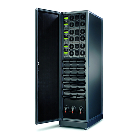
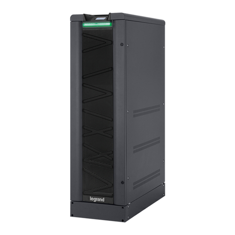
  9. LEGRAND 3 108 43 User manual

LEGRAND 3 108 43 User manual

SAFETY REGULATIONS
DANGER
Before carrying out any operation on the equipment, it is necessary
to read carefully these safety regulations. It is forbidden a use and
installation different than those specified in this instructions sheet.
CAUTION
This product should be installed in compliance with installation rules,
preferably by a qualified electrician. Incorrect installation and use can
lead to risk of electric shock or fire.
CAUTION
A battery can present a risk of electrical shock and high short circuit
current. The following precautions should be observed when working
on batteries:
a) remove watches, rings or other metal objects;
b) use tools with insulated handles;
c) wear rubber gloves and boots;
d) do not lay tools or metal parts on top of batteries;
e) disconnect the charging source prior to connecting or disconnecting
battery terminals;
f) determine if battery is inadvertently grounded. If inadvertently
grounded, remove source from ground. Contact with any part of a
grounded battery can result in electrical shock. The likelihood of
such shock can be reduced if such grounds are removed during
installation and maintenance (applicable to equipment and remote
battery supplies not having a grounded supply circuit).
CAUTION
• Do not dispose of batteries in a fire. The batteries may explode.
• Do not open or mutilate batteries. Released electrolyte is harmful to
the skin and eyes. It may be toxic.
• The batteries must be disposed of correctly. For the disposal
requirements refer to local laws and relevant standards.
WARNING: battery drawers must be added/replaced always
in multiples of 4 (1 KB). It is also necessary to ensure that
the brand of the 4 battery drawers is the same and that the
production dates are close (see the text yyWxx on the label
of the packaging box where yy is the year and xx is the
week).
PRESCRIZIONI DI SICUREZZA
PERICOLO
Prima di effettuare qualsiasi operazione è necessario leggere
attentamente queste prescrizioni di sicurezza. E’ vietata l’installazione o
l’utilizzo in modalità differenti da quelle indicate in questo foglio istruzioni.
ATTENZIONE
Questo prodotto deve essere installato in conformità con le regole
d’installazione e di preferenza da un elettricista qualificato. L’eventuale
installazione e utilizzo improprio dello stesso possono comportare rischi
di shock elettrico o incendio.
ATTENZIONE
Una batteria può costituire un rischio di scossa elettrica e di un’elevata
corrente di cortocircuito. Quando si opera sulle batterie devono essere
osservate le seguenti precauzioni:
a) rimuovere orologi da polso, anelli ed altri oggetti metallici;
b) utilizzare utensili con impugnatura isolate;
c) indossare guanti e scarpe di gomma;
d) non appoggiare utensili od oggetti metallici sulla parte superiore delle
batterie;
e) scollegare la sorgente di carica prima di collegare o scollegare i
morsetti della batteria;
f) verificare se la batteria sia stata inavvertitamente collegata a terra.
In questo caso, scollegare la sorgente da terra. Il contatto con
una parte qualsiasi della batteria messa a terra può causare una
scossa elettrica. La probabilità può essere ridotta se i collegamenti
di terra vengono interrotti durante l’installazione e la manutenzione
(applicabile ad apparecchiature e ad alimentazioni a batteria poste a
distanza, prive di circuito di alimentazione messo a terra).
ATTENZIONE
• Non gettare le batterie nel fuoco. Possono esplodere.
• Non aprire o rompere le batterie. L’elettrolita fuoriuscito può essere
dannoso per la pelle e gli occhi e risultare tossico.
• Le batterie devono essere smaltite in modo corretto. Per i requisiti di
smaltimento fare riferimento alle disposizioni locali e alle normative di
settore.
ATTENZIONE: I cassetti batterie devono sempre essere
aggiunti/sostituiti a multipli di 4 (1KB). E’ inoltre necessario
verificare che la marca delle batterie dei 4 cassetti sia la
stessa e che le date di produzione siano vicine (si veda il
dato yyWxx sull’etichetta della scatola di imballaggio, dove
yy sta per l’anno e xx per la settimana).
•3 108 54 Battery Drawer Assembly Instructions:
1. Join one end of the two 762 mm nylon laces and insert them in the
two proper slits placed in the front and the back side of the chassis
base.
2. Insert short and long wirings in the two proper slits and fix them
with proper brackets as shown in Fig. 1.
3. Place the first battery in the front side of the chassis (the handle
side) with red faston towards the external side of the chassis (the
handle side) as shown in Fig.2. Repeat this step for the remaining
batteries.
•
Procedura di assemblaggio di un cassetto batterie del kit 3 108 54:
1. Unire le due fascette in nylon da 762 mm ed inserirle nelle due
apposite fessure presenti nella parte anteriore e posteriore del
basamento del telaio del cassetto.
2. Inserire i cablaggi corto e lungo nelle apposite aperture presenti nel
telaio e fissarli con l’apposita staffa verificando la corretta polarità
illustrata in Fig.1.
3. Collocare la prima batteria nella parte anteriore del telaio
(lato maniglia) con il faston rosso verso il lato esterno del telaio
(lato maniglia) come illustrato in Fig.2. Ripetere la procedura per le
restanti batterie.
09/2016 -01 WP
LE05773AC
• Trimod HE UPS battery drawer
• Cassetto batterie UPS Trimod HE
3 108 43 - 3 108 45 - 3 108 54 - 3 108 75 ®
Fig. 1 Fig. 2
2
•3 108 54 Battery Drawer Assembly Instructions:
4. Connect the long wiring red cable to the red faston of the first
battery of the drawer (starting from the handle side) and the black
cable to the black faston of the second battery.
5. Connect the short wiring red cable to the red faston of the third
battery of the drawer and the black cable to the black faston of the
fifth battery (the last one).
6. Use one of the black middle cables to connect the black faston of
the first battery with the red faston of the second battery.
7. Use one of the black middle cables to connect the black faston of
the third battery with the red faston of the fourth battery
8. Use one of the black middle cables to connect the black faston of
the fourth battery with the red faston of the fifth battery
9. Group the cables and fix them through the plastic clamp (See Fig. 3).
10. Close the other side of the two 762 mm nylon laces in order to fix
batteries and cables to the chassis. All the cables must lay under
these two laces (See Fig. 4).
•
UPS Trimod HE Battery Drawer Installation/Replacement Procedure:
Three different procedures of Trimod HE battery drawer installation/
replacement are possible. Read carefully the installation and
maintenance manual in addition to the following instructions before
operating on the UPS.
WARNING: battery drawers must always be added/replaced
in multiples of 4 (1 KB). It is also necessary to ensure that
the brand of the 4 battery drawers is the same and that the
production dates are close (see the text yyWxx on the label
of the packaging box where yy is the year and xx is the
week).
Note: if total KB number installed in the UPS is varied after the
installation/replacement procedure, you must update the KB number
setting from the control panel.
After performing battery drawer installation/replacement, perform a
battery calibration to obtain precise data about UPS total runtime.
A) Battery drawers installation/replacement with UPS switched off
WARNING: the shut down procedure must only be applied
if the load is off or does not need powering by the UPS.
1. Keep the ON/OFF key on the control panel of the UPS unit pressed
for at least 2 seconds. When the display shows the text “Turn off the
UPS?”, press the ENTER key.
2. Open the mains input switch, the bypass input switch and output
disconnector switch by bringing them to the OFF position.
3. Open the battery breakers of the UPS and the Trimod HE
BATTERIES (if present). Press the ON/OFF key to discharge any
internal capacity.
4. Remove the 4 battery drawers related to just one KB. Do not
remove any battery drawer to add an additional KB.
5. Insert the 4 new battery drawers in the first 4 free slots
starting from the bottom.
6. Fix all the battery drawers using the supplied screws.
7. Repeat steps 4, 5 and 6 for all KB to be installed/replaced.
8. Follow the start procedure in the Installation and Maintenance
manual to turn the UPS on.
•
Procedura di assemblaggio di un cassetto batterie del kit 3 108 54:
4. Collegare il cavo rosso del cablaggio lungo al faston rosso della
prima batteria del cassetto (numerazione crescente a partire dalla
maniglia del cassetto) ed il cavo nero al faston nero della seconda
batteria.
5. Collegare il cavo rosso del cablaggio corto al faston rosso della
terza batteria e il cavo nero al faston nero della quinta batteria.
6. Utilizzare un cavo per il collegamento del faston nero della prima
batteria con il faston rosso della seconda batteria.
7. Utilizzare un cavo per il collegamento del faston nero della terza
batteria con il faston rosso della quarta batteria.
8. Utilizzare un cavo per il collegamento del faston nero della quarta
batteria con il faston rosso della quinta batteria.
9. Raggruppare e fermare con fascetta i cavi (vedere Fig.3).
10. Chiudere le due fascette in nylon da 762 mm in modo da fissare
saldamente le batterie e i cablaggi al telaio. Tutti i cablaggi devono
restare sotto le due fascette in nylon da 762 mm (vedere Fig. 4).
•Procedura di installazione/sostituzione di un cassetto batterie
UPS Trimod HE:
Sono possibili tre diverse procedure di installazione/sostituzione
dei cassetti batterie Trimod HE. Leggere attentamente il manuale
d’installazione e manutenzione per Trimod HE oltre alle seguenti
indicazioni prima di operare sull’UPS.
ATTENZIONE: i cassetti batterie devono sempre essere
aggiunti/sostituiti a multipli di 4 (1 KB). E’ inoltre necessario
verificare che la marca delle batterie dei 4 cassetti sia la
stessa e che le date di produzione siano vicine (si veda il
dato yyWxx sull’etichetta della scatola di imballaggio dove
yy sta per l’anno e xx per la settimana)
Nota: se la procedura di installazione/sostituzione modifica il numero
totale di KB installati nell’UPS, è necessario aggiornare l’impostazione
dei KB tramite pannello di controllo.
Dopo aver concluso le operazioni di installazione/sostituzione,
effettuare una calibrazione batteria per ottenere indicazioni precise
sull’autonomia totale dell’UPS.
A) Installazione/sostituzione cassetti batterie con UPS spento
ATTENZIONE: la procedura di spegnimento va applicata solo
se il carico è spento o non necessita di alimentazione dall’UPS
1. Tenere premuto il tasto ON/OFF per almeno 2 secondi. Quando
il display visualizza il testo “Spegnere l’UPS?”, premere il tasto
ENTER.
2. Aprire i sezionatori di rete, di ingresso bypass e di uscita portandoli
in posizione OFF.
3. Aprire i sezionatori di batteria dell’UPS e dei Trimod HE BATTERY
(qualora presenti). Premere il tasto ON/OFF per scaricare eventuali
capacità interne.
4. Estrarre i 4 cassetti batterie relativi a un solo KB. Per aggiungere
un ulteriore KB non rimuovere nessun cassetto batterie.
5. Inserire i 4 cassetti batterie nuovi nei primi 4 vani disponibili
partendo dal basso.
6. Fissare tutti i cassetti con le viti fornite in dotazione.
7. Ripetere i punti 4, 5 e 6 per tutti i KB da installare/sostituire.
8. Se si vuole avviare l’UPS, seguire la procedura di avvio sul
manuale d’installazione e manutenzione.
Fig. 3 Fig. 4
B) Battery drawers installation/replacement with UPS in
maintenance manual bypass
WARNING: during forced and maintenance bypass
operations, the load is not protected because it is
supplied from the bypass input line
1. Enable UPS forced bypass operation from the control panel.
2. Close the maintenance manual bypass switch bringing it to the ON
position.
3. Open the output disconnector switch bringing it to the OFF position.
4.
Shutdown the UPS by holding the ON/OFF key down for a few
seconds. When the display shows the question “Turn off the UPS?”
press the ENTER key.
5. Open the mains input switch and the bypass input switch bringing
them to the OFF position.
6. Open the battery breakers of the UPS and all the Trimod HE
BATTERIES (if present). Press the ON/OFF key to discharge any
internal capacity.
7. Remove the 4 battery drawers related to just one KB. Do not
remove any battery drawer to add an additional KB.
8. Insert the 4 new battery drawers in the first 4 free slots, starting
from the bottom.
9. Fix all the battery drawers using the supplied screws.
10. Repeat steps 7, 8 and 9 for all KB to be installed/replaced.
11. Verify that the output disconnector switch (S2) is open (OFF
position).
12. Close the battery breakers of the UPS and the Trimod HE
BATTERIES (if present). Close the mains input switch and bypass
input switch bringing them to the ON position.
13. Press the ON/OFF key to start up the UPS. When the display
shows the text “<ENTER> to confirm UPS turn ON”, press the
ENTER key. Wait for the UPS to be completely on.
14. Close the output disconnector switch bringing it to the ON position.
15. Open the maintenance manual bypass switch bringing it to the OFF
position. Enable the UPS in inverter (on-line) mode from the control
panel.
C) Battery drawers installation/replacement with UPS on-line
If the UPS has installed more than 1 KB for each 10 kVA of power
supplied on output (example: at least 4 KB for a Trimod HE 30), it is
possible to replace 4 battery drawers (1KB) at a time with UPS on-line.
The replacement procedure is the following:
1. Check that the UPS has installed more than 1 KB every 10 kVA of
power supplied on output.
2. Check that the UPS is not in battery operation and that battery
charger is in “maintenance” or “standby” status.
3.
Remove the 4 battery drawers belonging to the same KB (see Fig. 5
and 6). Do not remove any battery drawer to add an additional KB.
4. Insert the 4 new battery drawers and fix them with the supplied
screws.
5. Repeat steps 2, 3 and 4 for all KB to be installed/replaced.
WARNING: always replace only 1 KB at a time.
Note: it is always possible to add KB to a Trimod HE UPS or BATTERY
while the UPS is on-line installing new battery drawer in multiples of 4,
starting from the bottom free slots that are covered by the free batteries
slots protections of the kit 3 108 65.
Note: if the UPS transfers to battery operation during the procedure,
don’t remove or insert any drawer. It is possible to complete the
procedure when UPS returns to on-line operation.
Note: if during the procedure the input line mains is missing, the
runtime is reduced: carefully evaluate this possibility according to your
application before starting the procedure.
B) Installazione/sostituzione cassetti batterie con UPS in bypass
manuale di manutenzione
ATTENZIONE: durante il funzionamento in bypass forzato
e di manutenzione il carico non è protetto in quanto
alimentato dalla rete di ingresso bypass
1. Abilitare il funzionamento dell’UPS a bypass forzato dal pannello di
controllo.
2. Chiudere il sezionatore di bypass manuale di manutenzione
portandolo in posizione ON.
3. Aprire il sezionatore d’uscita portandolo in posizione OFF.
4. Spegnere l’UPS tenendo premuto per qualche secondo il tasto ON/
OFF. Quando il display visualizza la domanda “Spegnere l’UPS?”,
premere il tasto ENTER.
5. Aprire i sezionatori di ingresso rete e di ingresso bypass portandoli
in posizione OFF.
6. Aprire i sezionatori di batteria dell’UPS e di tutti i Trimod HE
BATTERY (qualora presenti). Premere il tasto ON/OFF per
scaricare eventuali capacità interne.
7. Estrarre i 4 cassetti batterie relativi a un solo KB. Per aggiungere
un ulteriore KB, non rimuovere nessun cassetto batterie.
8. Inserire i 4 cassetti batterie nuovi nei primi 4 vani disponibili,
partendo dal basso.
9. Fissare tutti i cassetti con le viti fornite in dotazione.
10. Ripetere i punti 7, 8 e 9 per tutti i KB da installare/sostituire.
11.
Verificare che il sezionatore d’uscita (S2) sia aperto (posizione OFF).
12. Chiudere tutti i sezionatori di batteria dell’UPS e di tutti i Trimod
HE BATTERY (qualora presenti). Chiudere i sezionatori di ingresso
rete e di ingresso bypass portandoli in posizione ON.
13. Premere il tasto ON/OFF per accendere l’UPS. Quando il display
visualizza il testo “<ENTER> per conferm. accensione UPS”,
premere il tasto ENTER. Attendere il completamento della
procedura di accensione.
14. Chiudere il sezionatore di uscita portandolo in posizione ON.
15. Aprire il sezionatore di bypass manuale di manutenzione
portandolo in posizione OFF. Abilitare il funzionamento dell’UPS a
inverter (on-line) dal pannello di controllo.
C) Installazione/sostituzione cassetti batterie con UPS on-line
Se l’UPS dispone complessivamente di più di 1 KB per ogni 10 kVA di
potenza erogata in uscita (esempio: almeno 4 KB per un Trimod HE 30),
è possibile sostituire 4 cassetti batterie (1 KB) alla volta con UPS on-line.
La procedura di sostituzione è la seguente:
1. Verificare che l’UPS abbia installati più di 1 KB ogni 10 kVA di
potenza erogata.
2. Verificare che l’UPS non sia in funzionamento a batteria e che il
caricabatterie sia nello stato “maintenance” o “standby”.
3.
Estrarre i 4 cassetti batterie relativi a un solo KB (vedi Fig. 5 e 6). Per
aggiungere un ulteriore KB non rimuovere nessun cassetto batterie.
4. Inserire i 4 cassetti batterie nuovi e fissarli con le viti fornite in
dotazione.
5. Ripetere i passi 2, 3 e 4 per ogni KB da installare/sostituire.
ATTENZIONE: sostituire sempre 1 solo KB alla volta.
Nota: è sempre possibile aggiungere KB a un UPS Trimod HE o al
cabinet Trimod HE BATTERY mentre l’UPS è on-line installando nuovi
cassetti batterie in multipli di 4, partendo dagli slot liberi in basso e
coperti con le mascherine di chiusura slot batterie vuoti del kit 3 108 65.
Nota: se l’UPS commuta nel funzionamento a batteria durante
l’operazione, non estrarre né inserire cassetti batterie. E’ possibile
riprendere l’operazione quando l’UPS torna a funzionare on-line.
Nota: se durante l’operazione viene a mancare la rete di ingresso,
l’autonomia è ridotta: occorre quindi valutare attentamente tale evenienza
in relazione all’applicazione prima di iniziare la procedura.
3
KB N°1
KB N°3
KB N°2
KB N°1
KB N°3
KB N°2
KB N°5
KB N°4
4
Fig. 5 Fig. 6

This manual suits for next models

3

Other LEGRAND UPS manuals

LEGRAND KEOR MOD User manual

LEGRAND

LEGRAND KEOR MOD User manual

LEGRAND KEOR MULTIPLUG 600 User manual

LEGRAND

LEGRAND KEOR MULTIPLUG 600 User manual

LEGRAND Daker DK 4.5-6 kVA User manual

LEGRAND

LEGRAND Daker DK 4.5-6 kVA User manual

LEGRAND NUMERIC 2000 HR-V IBB 28AH User manual

LEGRAND

LEGRAND NUMERIC 2000 HR-V IBB 28AH User manual

LEGRAND Trimod HE Reference guide

LEGRAND

LEGRAND Trimod HE Reference guide

LEGRAND KEOR SPX Series User manual

LEGRAND

LEGRAND KEOR SPX Series User manual

LEGRAND Daker DK 1 kVA User manual

LEGRAND

LEGRAND Daker DK 1 kVA User manual

LEGRAND KEOR PDU Series User manual

LEGRAND

LEGRAND KEOR PDU Series User manual

LEGRAND Trimod HE User manual

LEGRAND

LEGRAND Trimod HE User manual

LEGRAND Keor MOD Series User manual

LEGRAND

LEGRAND Keor MOD Series User manual

LEGRAND KEOR DC User manual

LEGRAND

LEGRAND KEOR DC User manual

LEGRAND KEOR HP Series Installation manual

LEGRAND

LEGRAND KEOR HP Series Installation manual

LEGRAND KEOR HP Series Installation and operation manual

LEGRAND

LEGRAND KEOR HP Series Installation and operation manual

LEGRAND 332 75 User manual

LEGRAND

LEGRAND 332 75 User manual

LEGRAND KEOR SPE R/T User manual

LEGRAND

LEGRAND KEOR SPE R/T User manual

LEGRAND NUMERIC intizon User manual

LEGRAND

LEGRAND NUMERIC intizon User manual

LEGRAND Keor MOD Series Manual

LEGRAND

LEGRAND Keor MOD Series Manual

LEGRAND DAKER DK Plus Series User manual

LEGRAND

LEGRAND DAKER DK Plus Series User manual

LEGRAND KEOR T EVO 10-60 KVA User manual

LEGRAND

LEGRAND KEOR T EVO 10-60 KVA User manual

LEGRAND KEOR HPE 100 kVA User manual

LEGRAND

LEGRAND KEOR HPE 100 kVA User manual

LEGRAND PREMIUS Operating manual

LEGRAND

LEGRAND PREMIUS Operating manual

LEGRAND DAKER DK Plus Series User manual

LEGRAND

LEGRAND DAKER DK Plus Series User manual

LEGRAND KEOR MULTIPLUG 600 User manual

LEGRAND

LEGRAND KEOR MULTIPLUG 600 User manual

LEGRAND KEOR S 3KVA 1 Manual

LEGRAND

LEGRAND KEOR S 3KVA 1 Manual

Popular UPS manuals by other brands

MGE UPS Systems EX 5 Installation and user manual

MGE UPS Systems

MGE UPS Systems EX 5 Installation and user manual

Vertiv Liebert APM Plus user manual

Vertiv

Vertiv Liebert APM Plus user manual

ABB PowerValue 11 LI Pro 600 VA user manual

ABB

ABB PowerValue 11 LI Pro 600 VA user manual

Eaton MX Frame 15000 RT Installation and user manual

Eaton

Eaton MX Frame 15000 RT Installation and user manual

TREND TONN/BAT installation instructions

TREND

TREND TONN/BAT installation instructions

Atlantis HostPower 1102 user manual

Atlantis

Atlantis HostPower 1102 user manual

SWEEX PP300 Quick installation guide

SWEEX

SWEEX PP300 Quick installation guide

Furman F1500-UPS E owner's manual

Furman

Furman F1500-UPS E owner's manual

CyberPower UP425 Specification sheet

CyberPower

CyberPower UP425 Specification sheet

Tescom DS3100A user manual

Tescom

Tescom DS3100A user manual

Powerware 8 - 15 kVA user guide

Powerware

Powerware 8 - 15 kVA user guide

HP R1500 user guide

HP

HP R1500 user guide

Sonnen sonnenProtect 2500-AU-ATS installation instructions

Sonnen

Sonnen sonnenProtect 2500-AU-ATS installation instructions

Vertiv Liebert NXL Series Operation and maintenance manual

Vertiv

Vertiv Liebert NXL Series Operation and maintenance manual

Omron S8BA-B120L instruction manual

Omron

Omron S8BA-B120L instruction manual

Ditek DTK-UPS400 user manual

Ditek

Ditek DTK-UPS400 user manual

Best Power Fortress 750 VA user guide

Best Power

Best Power Fortress 750 VA user guide

Alpha Technologies Tri Power X33 MOD HP2 Series user manual

Alpha Technologies

Alpha Technologies Tri Power X33 MOD HP2 Series user manual

manuals.online logo
manuals.online logoBrands
  • About & Mission
  • Contact us
  • Privacy Policy
  • Terms and Conditions

Copyright 2025 Manuals.Online. All Rights Reserved.