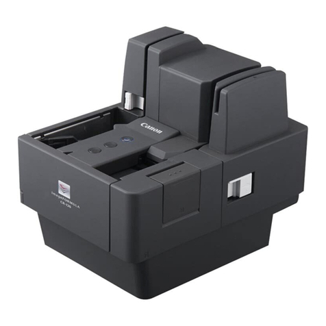
Leica Geosystems ScanStation C10 User manual

Leica
ScanStation C10/C5
User Manual
Version 5.0
English

2
ScanStation C10/C5, Introduction
Introduction
Purchase Congratulations on the purchase of a ScanStation C10/C5 instrument.
This manual contains important safety directions as well as instructions for setting
up the product and operating it. Refer to "6 Safety Directions" for further informa-
tion.
Read carefully through the User Manual before you switch on the product.
Product
identification
The type and the serial number of your product are indicated on the type plate.
Enter the model and serial number in your manual and always refer to this informa-
tion when you need to contact your agency or Leica Geosystems authorised service
workshop.
Type: _______________
Serial No.: _______________

ScanStation C10/C5, Introduction 3
Symbols The symbols used in this manual have the following meanings:
Trademarks • Windows is a registered trademark of Microsoft Corporation
All other trademarks are the property of their respective owners.
Validity of this
manual
This manual applies to the ScanStation C10 and C5 instruments. Differences for the
C5 model are marked and described.
Type Description
Danger Indicates an imminently hazardous situation which, if not
avoided, will result in death or serious injury.
Warning Indicates a potentially hazardous situation or an unintended
use which, if not avoided, could result in death or serious
injury.
Caution Indicates a potentially hazardous situation or an unintended
use which, if not avoided, may result in minor or moderate
injury and/or appreciable material, financial and environmental
damage.
Important paragraphs which must be adhered to in practice as
they enable the product to be used in a technically correct and
efficient manner.

4
ScanStation C10/C5, Table of Contents
Table of Contents
In this manual Chapter Page
1 Description of the System 8
1.1 Packing / Unpacking 8
1.2 Container Contents 9
1.3 Instrument Components 11
1.4 Power Supply 13
1.5 Other Components 19
1.6 Cabling 20
1.7 Field of View (FoV) 26
1.8 Description of the User Interface 27
1.9 HDS
Cyclone
Software Suite 39
2 Setting Up the Instrument 42
2.1 General Information 42
2.2 Scanner Setup on Tripod 43
2.3 Setup Over a Benchmark with the Internal Laser Plummet 45
2.4 Instrument Height 48
2.5 Power Supply and Charging 50

ScanStation C10/C5, Table of Contents 5
3Scanning 62
3.1 Switching the System On/Off 62
3.2 Ambient Conditions 63
3.3 Onboard Controls 65
3.3.1 Scan 68
3.3.2 Manage 69
3.3.3 Status 71
3.3.4 Configuration 74
3.3.5 Tools 76
3.4
Cyclone
SCAN 78
4 Troubleshooting 80
5 Care and Transport 86
5.1 Check & Adjust 86
5.2 Transport 87
5.3 Storage 88
5.4 Cleaning and Drying 89
5.5 Glass Cleaning Procedure 90
5.6 Adjustment of the Circular Level 92
5.7 Service of the Tripod 94
5.8 Adjustment of the Laser Plummet 95

6
ScanStation C10/C5, Table of Contents
6 Safety Directions 98
6.1 General 98
6.2 Intended Use 99
6.3 Limits of Use 101
6.4 Responsibilities 102
6.5 Hazards of Use 103
6.6.1 General 110
6.6.2 Distance Laser 111
6.6.3 Laser Plummet 116
6.7 Electromagnetic Compatibility EMC 119
6.8 FCC Statement, Applicable in U.S. 122
7 Technical Data 128
7.1 General Technical Data of the Instrument 128
7.2 System Performance 129
7.3 Laser Scanning System 130
7.4 Electrical 133
7.5.1 Scanner 135
7.5.2 GEB271 / GKL271 / GEB241 136
7.6 Physical 137
7.7 Accessories 142

8
ScanStation C10/C5, Description of the System
1 Description of the System
1.1 Packing / Unpacking
Unpacking When in its transport container, the ScanStation C10/C5 can sit in either a face-up or
face-down position.
Pack the instrument the same way it is delivered.
To take the instrument out of its container,
grasp the handle and the base of the instru-
ment, and lift.
Use caution due to the weight of the instru-
ment (13 kg).
C10_001

ScanStation C10/C5, Description of the System 9
1.2 Container Contents
Transport
container for
ScanStation C10/C5
a) ScanStation C10/C5 User
Manual
b) Ethernet cable
c) Allen keys
d) Protection cover
e) GHT196 distance holder for
height meter
f) GEB241 internal batteries
g) Cleaning tissue
h) GHM008 height meter
i) GEV230 AC power supply (not
supplied with system)
j) Power cable, country specific
k)
Cyclone
DVD and C10/C5
System CD-ROM
l) USB memory stick, not
supplied with system
m) ScanStation C10/C5
C10_002
abc de f fgh
ij kl m

10
ScanStation C10/C5, Description of the System
Transport
container for
ScanStation C10/C5
accessories
a) GEB271 external battery pack
b) GKL271 charging station
c) GEV225 AC power supply for
GKL271 charging station
d) GKL212 basic charger
including car adapter cable
e) GEB241 internal batteries
f) AC/DC adapter for basic
charger with daisy chain cable
C10_003
a
cde f
b

ScanStation C10/C5, Description of the System 11
1.3 Instrument Components
Overall system
a) ScanStation C10/C5
b) Laptop, not supplied with
system
c) GEV228 ethernet cable
d) GEB241 internal batteries
e) GEV230 AC power
adapter
f) GEV97 power cable
g) GEV225 AC power supply
for GKL271
h) GKL271 charging station
and GEB271 battery pack
i) Tribrach
j) Tripod
k) Transport container for
ScanStation C10/C5
l) Transport container for
ScanStation C10/C5
accessories
C10_004
a
b
c
d
f
g
e
h
i
j
k
l

12
ScanStation C10/C5, Description of the System
ScanStation C10/C5
a) Removable handle
b) Rotating mirror (laser and
camera aperture)
c) Battery compartment B
d) Circular level
e) Socket for power supply,
5pinfemale
f) Antenna
g) ON/OFF button
h) USB socket
i) Stylus
j) Touchscreen user interface
k) Battery compartment A
l) Ethernet socket, 8 pin
female
C10_005
a
b
c
d
e
f
g
i
h
j
k
l

ScanStation C10/C5, Description of the System 13
1.4 Power Supply
GEB241 Li-Ion
internal battery
GKL212 basic
charger
a) GEB241 internal battery
b) Electrical contacts
C10_006
a
b
a) Mains cable socket on the
charger
b) Socket for daisy chain cable
c) Charging bay for battery
d) Capacity and error indicators
e) Mains cable, country
specific
For more details refer to the GKL212 User Manual.
C10_007
b
c
d
e
a

14
ScanStation C10/C5, Description of the System
GKL221 profes-
sional charger
a) Mains cable, country specific
b) Mains cable socket on the charger
c) Adapter bays I and II for the GDI221
battery adapter
d) Vehicle adapter GDC221 - optional
e) Vehicle cable socket on the charger
f) Function indicator
g) Capacity and error indicators
h) Selection button
i) Status indicator for external battery
connection
j) GDI 221 battery adapter
k) Battery status indicators
For more details refer to the GKL221 User Manual.
d
hgi
ab c
C10_008
k
j
e
f

ScanStation C10/C5, Description of the System 15
GEB271 battery
pack The GEB271 battery pack can only be used together with the GKL271
charging station.
a) Battery pack
b) Battery connector interface,
female
c) Guide rail for fitting with
charging station
a
c
b
C10_009

16
ScanStation C10/C5, Description of the System
GKL271 charging
station
GKL271 charging station for the GEB271 battery pack.
a) Charging station
b) Battery connector inter-
face, male
c) Guide rail for fitting with
battery pack
d) Select button
e) Power and error indicators
f) Lock/unlock button
g) Clip for tripod mount
h) Port P2 for power output
i) Port P1 for power output
j) Port P3 for power input
a
c
hij
d
e
f
g
b
C10_010

ScanStation C10/C5, Description of the System 17
GEV225 AC power
supply
GEV97
ScanStation C10/C5
power cable
GEV225 AC power supply for the GKL271 charging station.
a) AC power supply cable
b) Connector 3 pin, male
c) Control LED; lights when the
AC power supply is
connected to a power plug.
d) AC power supply
e) Mains power cable, country
specific
a
b
e
d
c
C10_011
Connects ScanStation C10/C5 scanner to GKL271 charging station.
a) Cable
b) Connector 5 pin, male
a
b
GEV97

18
ScanStation C10/C5, Description of the System
GEV230 AC power
supply
AC power supply for the ScanStation C10/C5 scanner.
a) GEV97 ScanStation C10/C5
power cable
b) Cable and connector, 5 pin
female
c) Control LED; lights when the AC
power supply unit is connected
to an AC power supply.
d) GEV230 AC power supply unit
e) Mains power cable, country
specific
C10_012
c
b
a
d
e

ScanStation C10/C5, Description of the System 19
1.5 Other Components
GEV228 ethernet
cable
a) Cable
b) Connector, 8 pin male
c) Ethernet connector
a
b
c
GEV228

20
ScanStation C10/C5, Description of the System
1.6 Cabling
Cabling for
ScanStation C10/C5
with GEB271
battery pack
a) ScanStation C10/C5
b) GEV97 power cable
c) GEB271 battery pack
d) GKL271 charging station
a
b
c
d
C10_013
This manual suits for next models
1
Table of contents
Other Leica Geosystems Scanner manuals

Leica Geosystems
Leica Geosystems 3D Disto User manual

Leica Geosystems
Leica Geosystems T-Scan User manual

Leica Geosystems
Leica Geosystems BLK360 How to use

Leica Geosystems
Leica Geosystems BLC ARC User manual

Leica Geosystems
Leica Geosystems ScanStation P40 User manual

Leica Geosystems
Leica Geosystems Scan Station P16 Manual

Leica Geosystems
Leica Geosystems ScanStation P16 User guide