Lektro-Vend VS-99-D User manual


-
c
-T!!!EZC
TABLE OF CONTENTS
PAGE
WARRANTY................................................................................................................................................
1
GENERAL INFORMATION ........................................................................................................................
2
VENDING COMPARTMENT SPECIFICATIONS .......................................
.
...............................................
3
EQUIPMENT INSTALLATION.. ...............................................................................................................
4-5
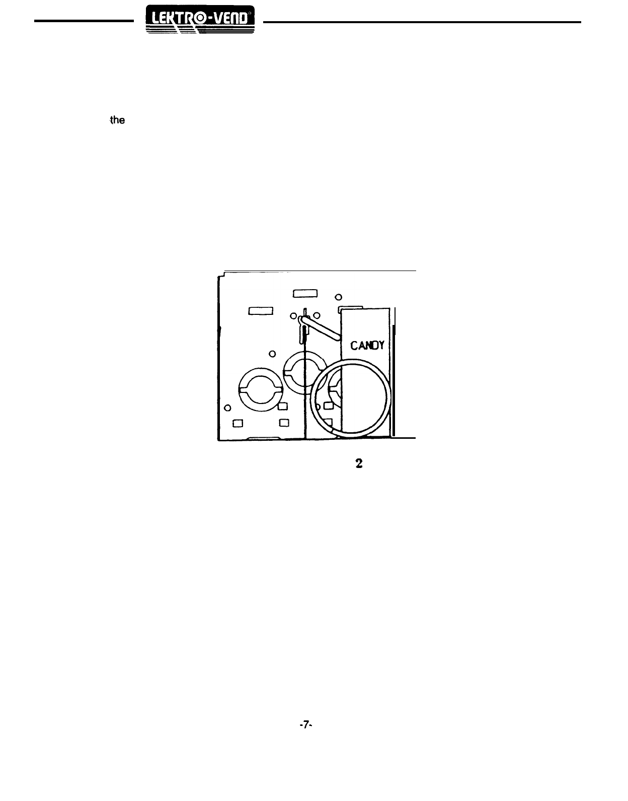
PRODUCT LOADING .............................................................................................................................
6-7
GUM
AND MINT LOADING .......................................................................................................................
8
CAROUSEL
LOADING
..............................................................................................................................
8
COLD FOOD
SIDE SET UP..
.......
i.............................................................................
.;.
.............................
9
REMOVING CAROUSEL JAM .................................................................................................................
10
CHANGING DIVIDER POSITIONS CAROUSEL TRAY...........................................................................
10
PRIMARY CABINET COMPONENT INFORMATION ..............................................................................
11
HEALTH SAFETY SWITCH OPERATION ...............................................................................................
12
SHOPPER SYSTEM OPERATION ..........................................................................................................
13
MACHINE THEORY
OF
OPERATION .....................................................................................................
14
ELECTRONIC SPECIFICATIONS ...........................................................................................................
15
ERROR
CODES........................................................................................................................................
15
ELECTRICAL SERVICE
SECTION
...............................................................................
i..
........................
16
DETAILED OPERATION
OF CONTROL
BOARD.. .............................................................................
17-25
COOLING SYSTEM INFORMATION .......................................................................................................
26
CLEANING AND MAINTENANCE ...........................................................................................................
SHIPPING POLICY .............................................................................................................................
28-z;
TROUBLE SHOOTING .......................................................................................................................
30-40
REFRIGERATION SYSTEM THEORY OF OPERATION ........................................................................
41
REFRIGERATION SYSTEM OPERATION ..............................................................................................
42
SOLENOID
COVER PANEL
REMOVAL ..................................................................................................
43
CHILLER ASSEMBLY REMOVAL AND INSTALLATION ........................................................................
43
PARTS
REPLACEMENT DIAGRAMS AND
PARTS LISTS
...................................................................
44
DOOR TRIM ASSEMBLY ...................................................................................................................
45-46
SHADOW
BOX
ASSEMBLY (SERVICE DOOR).................................................................................
47-48
DELIVERY DOOR (SERVICE DOOR) ................................................................................................
49-50
DOOR GLASS (SERVICE DOOR) ......................................................................................................
51-52
SERVICE DOOR ASSEMBLY (PRIMARY COMPONENTS) ..............................................................
53-54
COLD FOOD
AREA (PRIMARY COMPONENTS) ..............................................................................
55-56
LAMP
ASSEMBLY
(COLD FOOD
AREA) ...........................................................................................
57-58
TRAY SUPPORT ASSEMBLY ............................................................................................................
59-60
COLD FOOD DOOR ASSEMBLY .......................................................................................................
61-65
COLD FOOD DOOR
GASKET.. ...............................................................................................................
66
COIN
REJECT ASSEMBLY ................................................................................................................
67-68
POWER
SUPPLY ASSEMBLY ...........................................................................................................
69-70
POWER
SUPPLY WIRING HARNESS ....................................................................................................
71
POWER
SUPPLY SCHEMATIC.. .............................................................................................................
72
CHILLER ASSEMBLY .........................................................................................................................
73-76
CABINET ASSEMBLY (PRIMARY COMPONENTS) ..........................................................................
77-78
CAROUSEL COMPONENTS ..............................................................................................................
79-80
CAROUSEL ASSEMBLY .........................................................................................................................
81
CAROUSEL MOTOR ASSEMBLY ......................................................................................................
83-84
CABINET ASSEMBLY ........................................................................................................................
85-86
REAR CABINET ASSEMBLY ..............................................................................................................
87-88
ELECTRICAL SCHEMATIC
(WIRE
HARNESS
PART NOS.)
..................................................................
89

WARRANTY
(LIMITED)
Polyvend Inc. warrants this equipment to the original purchaser only to be free from significant defects in
material or workmanship, for a period of twelve (12) months, three years on the electronics, one year on the
cooling system to the extent such parts are warranted to Polyvend Inc. and one year on ballast for fluorescent
lights, The warranty period of twelve months applies to purchased components or to the extent such parts
are warranted to Polyvend, whichever is less. This warranty does not include
starters,light
bulbs and fuses.
Validators, changers and debit card systems are warranted according to the manufacturer of the units.
Any defective part, returned within the warranted period, will be repaired or replaced at Polyvend’s option.
This warranty does not cover the labor
for
removal or reinstallation associated with such parts. The returned
parts must be shipped, freight prepaid, to Polyvend. Polyvend will prepay the shipping cost of returned goods.
Any part returned under the terms of this warranty must be accompanied by the Polyvend Parts Returned
Form, with proper documentation.
The warranty is voided if a defect is caused by improper power supply, abuse of product, accident, alteration,
vandalism, improper cleaning, incorrect wiring, improper changer installed, improper installation, units
repaired or altered, where serial numbers have been altered, or improperly serviced (not in accordance with
the instructions given in the Service Manual).
Polyvend Inc. reserves the right to make any changes or improvements in its product without notice and
without obligation and without being required to make corresponding changes or improvements in products
theretofore manufactured or sold.
-l-

LEKTRO-VEND
VS-99 D
SNACK
/
FOOD COMBINATION
HEIGHT . .
72”
~WIDTH
. . .
~The
Lektro-Vend VS-99 D Snack/Food Combinations (Combo) machine is a revolutionary new concept in
vending equipment. It is designed to help the Operator increase his competitive position and service to small
to midsize locations. With this machine, a location can be serviced with not only snacks, candy and pastry,
but the location can now be serviced with juices, milk, yogurt, candy bars, sandwiches and other cold foods
all with one machine.
~The
machine comes equipped with six (6) shelves for snacks, candy and pastries and nine shelves for cold
food. The six shelves for snacks/candy can be
pumhased
configured in the manner that is best for your
location and each “compartment” can be priced individually. The nine shelves for cold food can setup with
any combination of compartments from four (4) to twelve (12) and each “shelf” regardless of the number of
compartments, is priced individually.
~DEPTH
. . . . . . . . . . . . . . . . . . . . . . . . . . . . . . . . . . . . . . . . . . . . . . . . . . . . . .
~SHIPPING
WEIGHT.
.
.
.
.
.
.
.
.
.
.
.
.
.
.
.
.
.
.
.
.
.
.
.
.
~ELECTRICAL
SPECIFICATIONS
I.........
(APPROX) 860 LBS
PRIMARY VOLTAGE
. . . . . . . . . . . . . . . . . . . . . . . . . . . . . . . . . . . . . . . . . . . . . . . . . . . . . . . . . . . . . . . . . . . . . . . . . . . . . . . . . . . . . . . . . . . . . . . . . . . . . . . . . . . . . . . . . . . . . .
1 1 OVAC
SECONDARY VOLTAGE
. . . . . . . . . . . . . . . . . . . . . . . . . . . . . . . . . . . . . . . . . . . . . . . . . . . . . . . . . . . . . . . . . . . . . . . . . . . . . . . . . . . . . . . . . . . . . . . . . . . . . . . . . . . . . . . . . .
24VAC
MAXIMUM CURRENT.
.
.
.
.
.
.
.
.
.
.
.
.
.
.
.
.
.
.
.
.
.
.
.
.
.
.
.
.
.
.
.
.
.
.
.
.
.
.
.
.
.
.
.
.
.
.
.
.
.
.
.
.
.
.
.
.
.
.
.
.
.
.
.
.
.
.
.
.
.
.
.
.
.
.
.
.
.
.
.
.
.
.
.
.
.
.
.
.
.
.
.
.
.
.
.
.
.
.
.
.
.
.
.
.
.
.
.
.
.
.
.
.
.
.
.
.
.
15AMP
VOLTAGE TO CHANGER
. . . . . . . . . . . . . . . . . . . . . . . . . . . . . . . . . . . . . . . . . . . . . . . . . . . . . . . . . . . . . . . . . . . . . . . . . . . . . . . . . . . . . . . . . . . . . . . . . . . . . . . . . . . . . . . . 24VDC
VOLTAGE TO VALIDATOR
. . . . . . . . . . . . . . . . . . . . . . . . . . . . . . . . . . . . . . . . . . . . . . . . . . . . . . . . . . . . . . . . . . . . . . . . . . . . . . . . . . . . . . . . . . . . . . . . . . . . . . . . . . . . . . 24VDC
VOLTAGE
TO
MOTORS . . . . . . . . . . . . . . . . . . . . . . . . . . . . . . . . . . . . . . . . . . . . . . . . . . . . . . . . . . . . . . . . . . . . . . . . . . . . . . . . . . . . . . . . . . . . . . . . . . . . . . . . . . . . . . . . . . . 24VDC
VOLTAGE
TO
SOLENOIDS
. . . . . . . . . . . . . . . . . . . . . . . . . . . . . . . . . . . . . . . . . . . . . . . . . . . . . . . . . . . . . . . . . . . . . . . . . . . . . . . . . . . . . . . . . . . . . . . . . . . . . . . . . . . . . 24VDC
-2-

VENDING COMPARTMENT SPECIFICATIONS
SNACK SIDE CHIPS/PASTRY
. . . . . . . . . . . . . . . . . . . . . . . . . . . . . . . . . . . . . . . . . . . . . . . . . . . . . . . . .
7
3/8
”
High X
51/2”
CANDY
. . . . . . . . . . . . . . . . . . . . . . . . . . . . . . . . . . . . . . . . . . . .. . . . . . . . . . . . . . . . . . . . . . . . . . . . . . . . . . .
7
318”
X 2
314”
HELIX SIZES AND CAPACITY
Model.
16E
16 Selections
Capacity 228
a
HELIX
PRODUCT
SIZE CAPACITY
3”
.............................................................................................................
6
2”
...........................................................................................................
10
1
314”
.....................................................................................................
12
1
l/2”
.....................................................................................................
14
1 3/16”
...................................................................................................
18
1”
...........................................................................................................
22
13/l
6”
....................................................................................................
27
CAPACITIES
12 12 12
00
00
00
8
db
d’o
d’o
db
db
db
14
I4
,I
00
00
00
1.
1.
II
22 22
2’
000000
d”o
d”o
ci”o
I
I
Model 21
E
Model
.24E
Model
,27E
Model
.30E
2 1 Selections 24 Selections 27 Selections 30 Selections
Capacity 307 Capacity 366 Capacity 47
1
Capacity 550
’
I2
db
00
db
db
dd
dd
db
db
0’;
6
‘$4
I.
I.
2*
21
27
000000
,I.
I.
1.
22 22
li
‘000000
10
to
10
00
00
00
COLD FOOD SIDE
The cold food compartments are pie shaped and the following are the approximate straight line dimen-
sions. Actual size of containers that will fit in the pie shaped area are not considered,
Vertical Clearance: 4
318”
Front to Back Dimension: 4
7/8:
Front of pie (One corner to the other):
Compartments
Dimensions
12
3
l/2”
67”
4
8
l/2”
-3-

Remove all external packing material.
Inspect equipment for shipping damage. If evident file claim immediately with the carrier (see Shipping
Procedures).
Remove keys from product dispensing compartment (in small manila envelope), unlock the service door
and remove the shipping material.
Check the operation of the service door and locking mechanism. They should operate smoothly and latch
at all three locking plates.
If optional Gum & Mint installed, slide the shipping clip to the left located on the left side of the gum and
mint assembly. Release the tray on the right side with the latching clip and slide the tray in and out to
ensure that everything
slides smoothly.
Place machine into position and adjust leveling legs so the machine is level and all the legs sit firmly on
the floor.
It is extremely important to provide the machine with sufficient air flow for cooling. Provide a MINIMUM
OF SIX (6) INCHES SPACING BETWEEN THE WALL AND THE BACK OF THE MACHINE.
CAUTION: DISCONNECT POWER TO THE VENDING MACHINE BEFORE REMOVING THE CONTROL
BOARD OR COIN CHANGER OR WORKING ON ANY COMPONENTS IN THE MACHINE.
Install coin mechanism and bill validator (if required). NOTE: Changer must be installed in machine
to operate control board. All changers and validators used in this machine must be 24 volt.
Plug service cord into 11 OVAC source using the three prong grounded plug provided. If a grounded oulet
is not available, use a proper external ground on all locations.
NOTE: In order to comply with electrical safety regulations and Underwriters Laboratories requirements, all
electrical equipment must be properly polarized and grounded. The Polyvend machine is wired so that it is
properly polarized in accordance with the electrical code. If the wall outlet is wired and grounded properly,
then the vending machine will connect properly.
Shown in
view;
A and 6are two properly grounded and polarized wall outlets. One is a three wire grounded
type wall outlet (See View A) and the other is a two wire wall outlet (See View B) with an adapter in place.
Should the polarity at the wall outlet appear any way other than that shown below, the outlet should be rewired
by qualified personnel.
THREE WIRE
GROUNDING T
Y
PE
WALL OUTLET
CIRCUIT GROUND
OR COMMON
~TWO
WIRE
WALL OUTLET 7
GROUND
\
\
CIRCUIT GROUND.
OR COMMON
,HOT
VIEW A
-4-
VIEW
8

CAUTION: DISCONNECT POWER TO THE VENDING MACHINE BEFORE REMOVING THE CONTROL
BOARD OR COIN CHANGER OR WORKING ON ANY COMPONENTS IN THE MACHINE.
Check and make sure that the power indicator light (24 volts) is illuminated on the control board.
Test the coin mechanism and bill validator (If installed) to ensure smooth operation. If the operation of the
coin mechanism is not smooth, check to make sure that you have proper alignment of the changer with
the coin return lever. Make sure that the coin tubes have plenty of money in them to test the validator.
Fill the coin tubes on the coin changer located on the front door of the machine. It is very important to fill
the 25c,
1Oc
and
5c
tubes for proper change pay back and operation of the bill validator (if installed).
NOTE: The maximum amount of change a Coinco 9302LF will hold is $38.60, $22.50 in quarters, $12.00
in dimes and $3.40 in nickels. The maximum amount of change that a Mars TRC-6010XV will hold is
$29.95; $16.75 in quarters, $9.80 in dimes and $3.40 in nickels.
Operate each vending dispenser, using coins. Operation should be smooth.
In the large manila envelope is a sheet with the sticker “PLACE FOOD HERE”. Peel each sticker off and
place it on the delivery door rail just below delivery door on the cold food side. The position should be in
the center of the compartment that the selection will vend from.
Cooling system is not set from the factory and normally requires adjustment to the environment it will
operate in. Do not change cooling system adjustment unless inside cabinet area is above 40 degrees
or below 36 degress on digital thermometer after unit has been running for at least one hour. Adjustments
should be no more than
l/8
turn then wait to allow system to balance out properly. See cooling system
information page 42 for complete instructions on set up of machine.
Load the machine with product (See section on product loading).
Place the price stickers on the trays to the right of the selection stickers and on the clear plastic vend doors
above the selection stickers. Set the prices of the products in the control board (See price setting)
Check to make sure that the Vend Option: Forced Vend is set at the desired setting. See Forced Vend
mode.
Set all other options to the desired setting. See vend options.
On the refrigerated side of the machine is a blower system designed to keep condensation from forming
on the plastic delivery doors. The system directs warm air across the delivery doors. Make sure that the
unit is blowing air across the delivery doors.
Close the front door and lock the machine.
-5-

PRODUCT LOADING
Helix Tray Dispenser
There are several helix pitches available. To insure proper operation and maximum capacity, the product size
should closely match the opening between the windings of the helix so as not to be tight, but should fill most
of the opening.
The helix sizes available are listed below
CANDY HELIX
27CT
22CT
18CT
SNACK HELIX
(DUAL HELIX)
14CT
12CT
1 OCT
PRODUCT LOADING
PRODUCT THICKNESS
3/4”
thin candy bar
1”
medium candy bar
1 13/l 6” large candy bar
PRODUCT THICKNESS
1
l/2”
medium chip bag or pastry
1
3/4”
chip or pastry
2” large bag chip or pastry
To load a tray, lift up on the front of the tray and slide it out to the stop, then let it tilt down into the loading position.
At this point, check that each helix is in its proper position. The figure below shows the proper position.
Starting at the front of the tray, insert a product between each winding of the helix so the name of the product
is displayed forward. Be sure to place the product all the way to the bottom of the tray and tilt free end at the
top backwards. Fill from front to back and be sure not to miss any positions. Note: product must rest on tray
NOT on helix. After filling the tray, lift the front of the tray and push it back in until it hits the stop.
-6-

NARROW PRODUCT LOADING
In order to keep narrow products positioned properly the use of one of the spacer rails may be required.
For
additional rails order part no. 099-5107.
To install
-the
guide, press on the tray divider as shown in Figure 2 below.
FIGURE
2
-7-

jOPTIONAL)
GUM AND MINT TRAY LOADING
SLIDE OUT DRAWER STYLE
The four select gum and mint dispenser is available in kit form or can be factory installed in a new machine.
Each selection will hold up to 20 packs of gum (5 stick per pack) or roll candy up to 5 inches in length. There
is a small metal tab that can be installed to allow you to dispense small rolls of anti-acid tablets or similar size
products.
All machines are prewired from the factory so you can install the gum and mint kit at a later date. The harness
for the gum and mint assembly is plugged into the motordistribution board (same board the trays are plugged
into).
LOADING INSTRUCTIONS
~Release
the tray by pushing on the tab located on the right side of the tray and pulling the tray out to the stop.
To load, push the cover toward the rear of the machine. The two wide product selections are fitted with width
adapters, installed for dispensing longer products up to 5 inches in length. Place the packs of gum or rolls
of mints on their side and stack towards the back of the gum and mint tray. Upon filling each selection, slide
the tray cover forward back into place. Then slide the tray back into the machine until latched into position.
CAROUSEL LOADING
Open the refrigerated door
section.
To
step
the carousel there is a three (3) position service switch in the upper
right hand corner of the cabinet. If you press this button the carousel will step 30 degrees, l/l 2 of turn, which
is one small compartment. If you pull the stepping switch out the carousel will run continuously. Load the tray
compartments with the desired products. Then close the refrigerated door and rotate the carousel making
sure all items are in their correct compartment according to the pricing of that tray. When you first set up the
machine it will be necessary to reset the health control by going into the service mode and then come back
out. After the health control has been reset it will not be necessary to reset it. The health control will
automatically reset). The machine will then display the message “ENJOY ONE OF OUR FINE SNACK
PRODUCTS”. In 30 minutes the cold food timer will clock out and the health control will ensure that the
temperature inside the refrigerated area is below 45 degrees. Should the temperature be above 45 degrees,
only the cold food side will be shut down and NOT the vend selections. If a cold food selection is chosen,
the display will say “Make Alternate Selection”.

COLD FOOD SIDE SETUP
The Cold Food Side of the Combo unit comes equipped with nine (9) revolving shelves. The shelves are
designed in two halves, two 160 degree segments. Each segment can be quickly removed to change the
number of compartments per shelf and or to clean.
REMOVING TRAY HALVES
The tray halves can be easily removed to change the divider configuration for loading or for cleaning. They
are removed by the following procedures:
Underneath the center
of
the tray half is a leaf spring that is holding a stud attached to the tray. Pull down
on the spring to release the stud and pull the tray outward towards you.
2.The rear of the tray is inserted into a groove in the collar that is attached to the tray column. A slight
outward pressure may be required to disengage the rear of the tray from the groove.
3.
~The
lip on each tray is designed with tabs that extend beyond the back edge of the tray. These tabs
slip underneath the adjoihing tray half to lock the two halves together and provide support for each other.
4.
When the tray half is removed you will notice that the 12 and 6 compartment trays have a security top
with clips that slip through the top and over the dividers. After
changing
the dividers or
cleaning
the tray
replace the security covers and clips. These are required to keep the dividers from being bent sideways
and allowing the food from being removed from the next compartment.
CAUTION: ALWAYS INSTALL THE SECURITY COVER AND CLIPS
-9-

REMOVING A CAROUSEL JAM
NOTE:
If the carousel drive motor ever fails and the carousel is not in a position that the tray halves can be
removed, do the following to remove the chain.
1.
In the bottom of the machine is a wing nut wrench. (A long piece of metal pipe with notches
at one end located on the left side in the bottom.)
2.
The wrench is used to reach the wing nut on the drive motor bracket which is located on the back
wall. (Insert the wrench under the top sprocket.)
3.
Loosen the wing nut only enough to drop the chain off the sprocket so the carousel can be turned
by hand in the reverse direction to unjam the unit. Do not loosen the wingnut enough that it
drops off. Once you have unjammed the carousel reinstall the chain, ensuring that the tray
dividers line up with the right security panel by each delivery door on the machine.
NOTE: Care must be taken to not over tighten the sprocket chain or the unit may bind up.
CHANGING DIVIDER POSITION CAROUSEL TRAY
Divider positions can only be changed while the tray half is removed from the machine.
1.
Loosen the screw holding the clip in place. Then
remcve
the security cover and clip. See
Figure 3.
2.
Lift the rear of the divider first with a slight upward pressure. This allows the divider latch
to slip out of the tray bottom. To replace the divider reverse this sequence of steps.
3.
Replace the security cover and clips as required. Slip clip under screw and tighten.
See figure 3 below.
SECURITY CLIP
SECURITY COVER
SCREW
\_._==-
/
TRAY BOTTOM

PRIMARY CABINET COMPONENT INFORMATION
HIGH VOLTAGE POWER SUPPLY
The high voltage power supply is located in the bottom of the machine on the left hand side. inside of the power
box are the step down transformers, ballast for the lights,
RFI
filter and surge suppressor. The starters for
the three fluorescent lights are located on the front of the power supply box. There are four (4) circuit breakers
located on the front of the power box. The left 3 amp circuit breaker on the of the box is for the control board,
changer and validator if installed. The next circuit breaker to the right is the 12 AMP breaker for the 24 volts
for the carousel motor. The next circuit breaker to the right is the 2 amp breaker for the fluorescent lights and
the final circuit breaker to the right is the main 15 amp breaker for the entire machine. To the right of the circuit
breakers is the main power switch for the entire machine.
~HELIX
TRAY REMOVAL
NOTE: It is important to remember that the top tray (A row) in this machine will not interchange with any other
tray in this machine.
To remove a tray lift up slightly on the tray front while pulling the tray out to the loading position. Disconnect
the tray harness from the main motor distribution board. Set the tray harness on top of the tray. Pick up on
the front of the tray lifting the tray upward at 45 angle and outward. Grasp the tray at the front and the rear
and place it on a work surface.
To replace, reverse the operation. Grasp the tray, set the rear of the tray on the rails while holding the front
of the tray at a
459
angle upward. Slide the tray in until stop on the bottom of the tray clears the front cross
rail. Then lower the front of the tray while sliding it in until it comes to the stop. Feed the tray harness around
and plug it into the main motor harness assembly.
-ll-

~HEALTH
SAFETY SWITCH OPERATION
Operation and Testing
The international control board incorporates a Health Safety sensing system. If the temperature inside the
cold food compartment reaches 45 degrees or higher, during normal operations or there is a loss in power,
the control board will not allow any cold food to be vended (all of the H selections).
If this condition exists “Make
Another
Selectron”
message will be displayed when the customer tries to vend a cold food selection.
The control board also incorporates a timer which allows the cold food box 30 minutes to cool down below
45 degrees before the Health/Safety system becomes active. At the initial start-up of the machine or after an
over temperature condition has occurred the Health/Safety switch timer must be set manually. But for normal
food loading and servicing the Health/Safety switch timer is automatically reset when the main door is closed.
To manually reset the Health/Safety switch for the 30 minute timer:
1,
First open the main door.
2.
~Press
the Mode button to go into the service mode, then press the mode button again.
3.
The health control is now reset and the timer will start running when the front door
of
the machine is closed.
If power is lost or the temperature inside of the cold food area is above 45 degrees the health control will
have to be manually reset so it will be necessary to repeat the above steps. Under normal operation when
a person comes to load the machine it will not be necessary to manually reset the health control timer.
To test the health control sensor and make sure that the system is functioning properly do the following to
a machine that has been operating for at least one hour, note that is normally a two person operation.
Open the main and cold food doors.
Remove one half of the bottom tray.
Rotate the carrousel until you are able to reach the health safety sensor which is located in the lower left
hand corner of the cold food compartment extending out in front of the evaporator fan.
Close the doors and then vend the bottom selection on the cold food side.
Reach in and hold the probe in your hand to warm it above 45 degrees. Then remove your hand and allow
the door to close completely.
Try and vend another cold food compartment. When the message MAKE ANOTHER SELECTION is
displayed you know that the health safety switch has kicked out and will not allow another cold food vend.
-12-

%HOPPER SYSTEM OPERATION
This machine features a Shopper Mode Merchandising System. The rotation of the carousel is started by
pressing the “Press to View” bar located on the main door. This energizes the carousel motor relay, applying
power to the carousel motor. A cam on the motor allows the motor to turn 180 degrees which in turn rotates
the carousel 30 degrees
(l/12
turn) or the equivalent of one small compartment width. When the bar is
depressed and held, the motor continues to rotate the carousel. The carousel is driven by a chain drive and
sprocket system.
NOTE: Should something cause the carousel to jam and stop rotating and the position of the carousel is such
that you can not remove a tray section follow this procedure. Located in the bottom of the machine on the far
left side is a piece of metal tubing with one end slotted. Reach over the top of the carousel and unscrew the
wing nut tension screw. Remove the chain from the large sprocket and then reverse the direction of the
carousel to remove the item causing the jam
~Carousel
Alignment
~When
installing the chain drive on the carousel it is very important that the carousel be aligned with the front
door of the machine. To align the front door with the carousel dividers, loosen the tension on the chain drive
enough to be able to move the chain one sprocket in the direction required to align the carousel and then
tighten the chain. Be careful not to over tighten the chain.
~Carousel
Motor Assembly Adjustment
If the carousel motor is stopping prematurely or is not stopping at all it may be necessary to adjust the carousel
motor in relation to the stepping microswitch. Remove the top two tray halves in the carousel assembly. To
adjust the motor there are four hex headed screws on top of the carousel motor assembly. Loosen the four
screws and slide the motor to the left or the right to adjust it. Only a slight amount of movement is required
to change the adjustment. Then retighten the four screws and test the unit.
~BLOWER
SYSTEM FOR COLD FOOD DOOR
L
~The
blower system is designed to keep condensation from forming on the plastic delivery doors. The system
directs warm air across the delivery door from the right side and should be kept clean.
-13-

THEORY OF OPERATION
When inserting coins and the highest price set in the machine is reached, no additional coins will be accepted
by the changer. When inserting bills and the highest vend price set in the machine is reached the validator
will not accept any additional bills and the changer will not accept any coins.
By pressing a selection letter and number the control board will compare the price of that selection with the
credit accumulated and if there is enough a vend motor or a solenoid will be energized. When the vend is
completed the control board will then determine if any change is due and dispense the correct change from
the changer.
Should a vend motor fail to return to the home position in six( 6) seconds the control board will assume that
the motor is jammed. The control board will automatically take the selection out of service (remove it from the
machine configuration and inform the customer to “Make an Alternate Selection”. A jammed motor does not
affect any other selection in the machine. The selection that is jammed will be displayed on the digital display
as out of service when the mode button is pressed. The vend motor can be put back into service when the
mode button is pressed and the selection has been service vended two (2) times.
~If
the level of coins in the changer is too low the control board will display the message “USE CORRECT
CHANGE” on the display and will also shut down the bill acceptance feature (if validator is installed).
When going into the Service Mode the control board will display the following message if there is a problem.
A.
~The
selection letter and number of a faulty or jammed motor along with an error code. Error 1 or
Error 2
B.
Error code 3 = Loss of communication with changer.
Charger has malfunctioned
C. Error code 4 = EEPROM Sum check error.
NOTE: Error4
=
Prices have been inadvertently altered and all prices have automatically been set to maximum
by the control board. To clear these prices, reset pricing as desired.
If a bill
validatoi
is being utilized the machine can be programmed to Forced Vend or a Non-Forced Vend
system. When the Forced Vend option is used the customer must make a vend when the bill is accepted.
Thus, the customer cannot use the machine as a change maker.
~CAUTION:
When removing the control board extreme care should be taken to avoid introducing static
electricity into or onto the board. Under no circumstances should the board be placed on anything made of
metal. To remove the control board simply disconnect power to the control board, remove the control board
cover, unplug the harness and remove the screws mounting the control board to the door.
-14-

ELECTRONIC SPECIFICATIONS
1.
2.
3.
~A.
~B.
~C.
Prices can be set to a maximum of $99.95.
The control board will interface with the following 24 volt coin mechanisms:
A. Coinco 9302LF
15 pin
B. Mars TRC-601 OXV
15 pin
The international control board will interface with the following validators and will accept $1 bills, $2 bills,
$5 bills, $10 bills and $20 bills.
Coinco BA32SA’
*Option switches should be set as follows, swithes 1 2,4,5 should be “off” switches 3,6,7,8 should be “on”.
Mara
NB-1 B 24 volt
Mars
VFMl
-L2-U2C
Mars VFM3-L2-U2C’
*Option switches should be set as follows, switches 1,2,3,4,5,6,7,8 should be in the “off” position.
/
TERROR
CODES
1.
Error 1
=
Too little motor current
2.
Error 2
=
Too much time to complete the vend (6 seconds)
3.
Error 3
=
The control board has lost communications with the changer (changer has
malfunctioned).
4.
Error 4
=
EEPROM sum check error.
NOTE: Error 4
=
price have been inadvertently altered and all prices have automatically been set to maximum
by the control board. To clear these prices, reset pricing as desired.
-15-

ELECTRICAL SERVICE SECTION
MODES OF OPERATION
The system will operate in one of two modes, sales or service. On power up (after completing configuration),
the machine is in the sales mode. Service mode may be selected by pressing the mode button mounted on
the control board. The system will return to the sales mode if the mode button is pressed or after 25 seconds
of no service mode activity the control board will automatically return to the sales mode.
SALES MODE
In the sales mode, the control board will control the dispensing of products according to customer credit and
selection inputs. The control board will communicate with the coin mechanism and dollar bill validator (if
installed) so, as credit is entered it will be shown on the scrolling display. If there is inadequate change
available, the coin mechanism will indicate that an “Exact Change situation” exists and the control board will
show on the scrolling display “Please Insert Exact Money”.
When a customer makes a selection on the key pad, A thru H and (within 5 seconds) numbers 0 thru 9, the
accumulated credit will be compared to the price set for this selection and if credit is equal to or exceeds the
set price, the corresponding motor or solenoid will be energized. If the vend is successful the price will be
deducted from the credit value and the change returned. The vend will be considered unsuccessful if the motor
does not receive sufficient current or fails to reach the home position within (6) seconds.
On the cold food side the product delivery doors are locked by solenoids. When a vend is made, the lock which
allows the door to be opened is held open for 20 seconds, then it releases. If the door is not open the machine
will wait for an indication from the door switch that the door is open. After approximately five minutes the
machine will reset or it will automatically reset if the carousel is rotated.
SERVICE MODE
The service
wde
can be entered by pressing the “MODE BUTTON” located on the control board. By using
the numbers and letters on the alphanumeric key pad, the operator can program and review the features of
the control board. Upon pressing the mode button, will display any faulty motors, that have been detected
as bad or jammed and then removed from service by the control board.
-16
-

DETAILED OPERATION OF CONTROL BOARD
At the time of delivery from Polyvend Inc. the control board will be set as follows:
1.
2.
-3.
4.
5.
6
7.
All vend options will be off.
The cash accountability will be set to $OO,OOO.OO
NOTE: Due to factory testing the total will not be exactly $OO,OOO.OO
All of the prices will be set to $00.50
The total number of vends non-resettable will be 000000.
NOTE: Due to factory testing the total will not be exactly 000000.
The time and date will be blank with the clock turned off
The timed shut down intervals will be off and blank.
The promotional rows will be blank.
~DOORS
SWITCHES
This vendor is equipped with a door activated on/off switch which shuts off the 24 volts
AC+power
in the
machine when the door switch is pulled out. When the front door is opened this switch is in the “on” position
and stays in that position until the plunger is pulled out. The switch is mounted underneath the Gum and Mint
on the left hand side. The other switch beside the power switch is the Health/Safety switch to start the timer
for the Health/Safety control circuit.
CAUTION: The power door switch DOES NOT TURN OFF THE 120 VAC power to the lights, or cooling
system.
3.
~2.
~3.
COIN DISPENSING
To dispense nickels, dimes and quarters from the changer, press the service mode button. Now press
selection button
#l
then press selection button ‘A” for nickels to be dispensed,
“B”
for dimes to be
dispensed and
“C”
for quarters to be dispensed.
MOTOR COUNT
While in the service mode, press selection button
#2
to display the total number of functioning motor. On
the display the message “MOTORS” and the total number found in the machine will appear.
MOTOR REMOVAL
To remove a motor from the configuration while in the service mode, press selection button
#3.
The
control board will reconfigure to the currently functioning motors. The display will show “CONFIGURED”
upon completion.
-17-

4. ACCOUNTABILITY SYSTEM
1
~CASH
ACCOUNTABILITY
While in the service mode press selection button
#4.
The display will show “ACCOUNTING” then press
one of the following letters
A
=
Total cash accountability, the total value of all paid sales which will rollover after
$99,999,95.
B
=
Total bill validator accountability (if bill validator installed), the total number of bills taken in
which will rollover after 99,999.
~Note:
This feature can not be reset.
~To
exit this mode, press selection button
#13.
-2.
~TOTAL
NUMBER OF PRODUCTS VENDED
While in the service mode press selection button
#4.
The display will show “ACCOUNTING”. Press
selection button
“C”
to display the total number of products vended from this machine, which will rollover
after 79,999,920. This functions is non-resettable.
-3.
TOTAL NUMBER OF PRODUCTS VENDED (RESET-TABLE FUNCTION)
awhile
in the service mode press selection button
#4.
The display will show “ACCOUNTING”. Press
selection button
“D”
to display the total number of products vended since the last reset, which will rollover
after 79,999,920.
-4.
RESET ALL RESET-TABLE FUNCTIONS AT ONCE
While in the service mode press selection button
#4.
The display will show “ACCOUNTING”. Press
selection button “E”. The display will show “RESET”. To reset all resettable functions only, press selection
button “F”. All functions will reset to
“0”.
5. DOWNLOAD DEX/UCS
While in the service mode press selection button
#4.
The display will show “DEWUCS” and the control
board will down load the information to the hand held unit. Upon completion of the download of the
resettable items, it will be necessary for the operator to then reset all of the resettable functions. The
download of the control board does not automatically reset these items to 0. They must be manually
reset (see step 4 above).
-18-
This manual suits for next models
1
Table of contents
Popular Vending Machine manuals by other brands

Necta
Necta Zenith Fresh Brew Instant Installation, operating and maintenance manual

Seaga
Seaga SM16S Service and parts manual

CPI
CPI Merchant Media 2 Combo Programming guide

Bay-Tek
Bay-Tek PRIZE HUB Modular Service manual

AIRSLED
AIRSLED VM2400 owner's manual

A&A Global Industries
A&A Global Industries Triple Crown Assembly manual