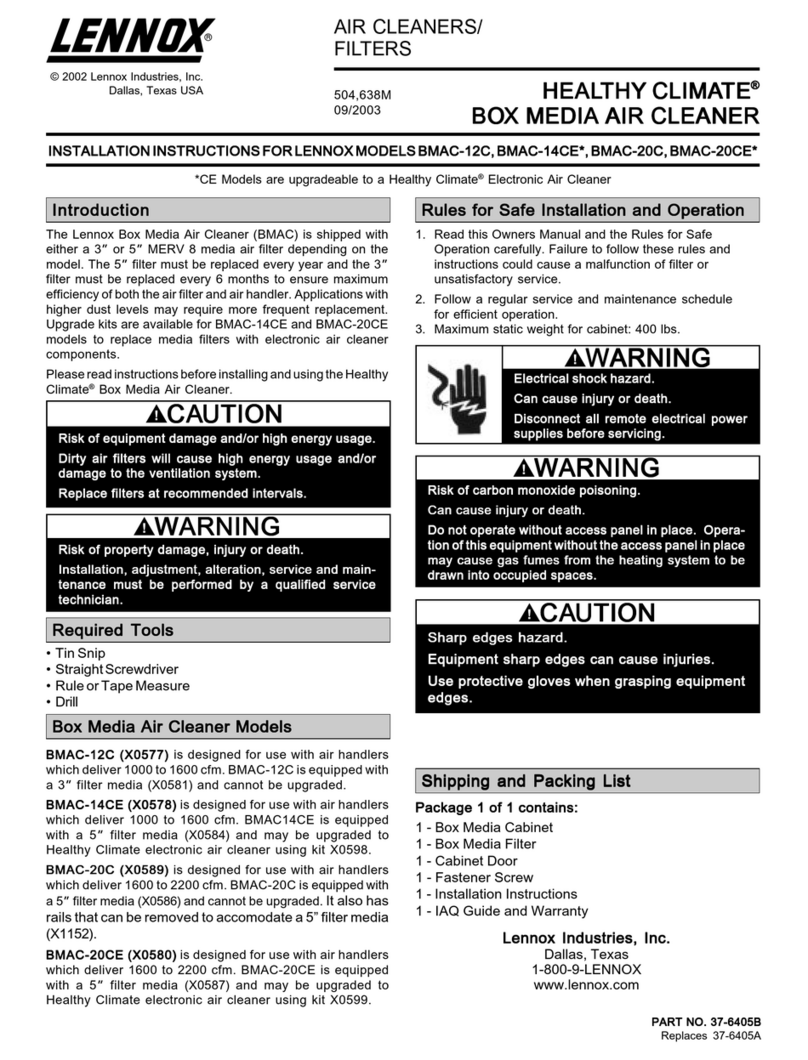
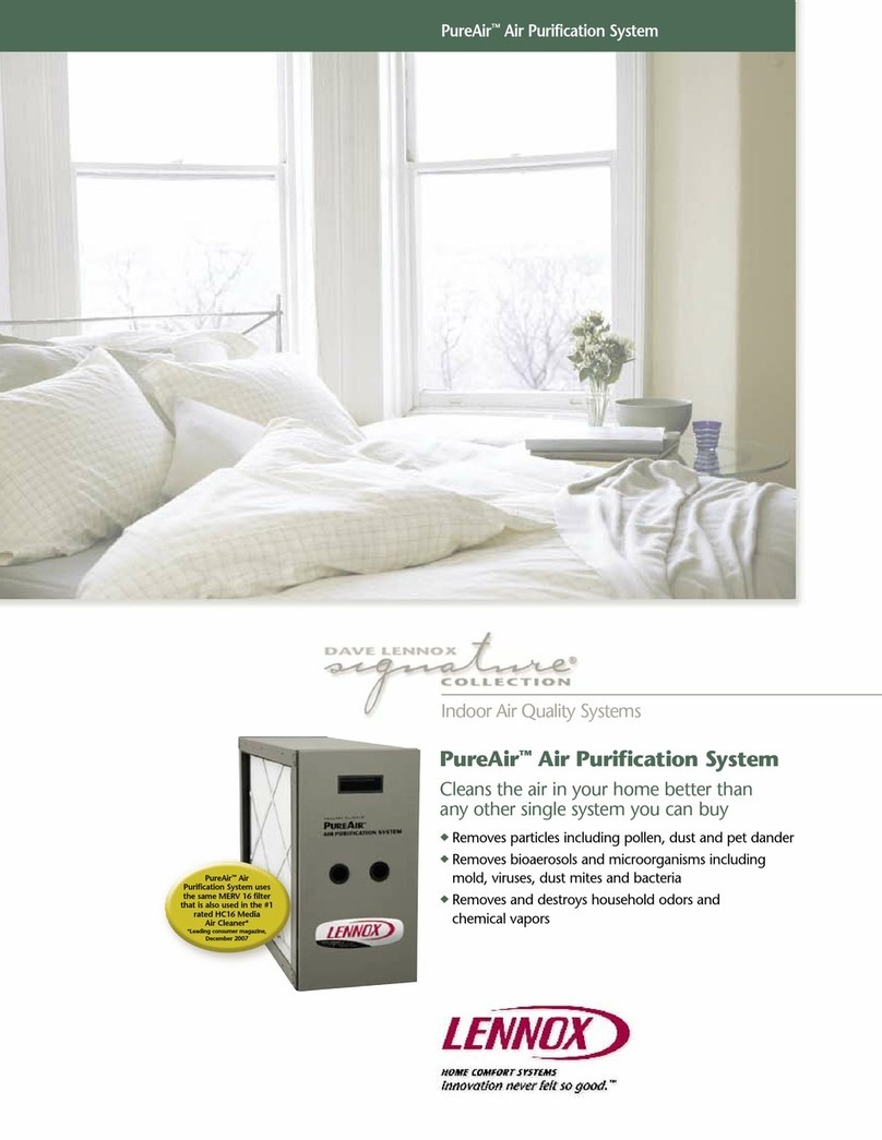
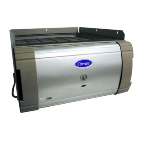
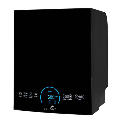
Lennox Healthy Climate PureAir PCO-20P-2 User manual

PureAir™ AIR PURIFICATION SYSTEM
PHOTOCATALYTIC OXIDATION (PCO) TECHNOLOGY
HEALTHY CLIMATE®
505,093M
09/2007
AIR CLEANERS/
FILTERS
INSTALLATION AND MAINTENANCE INSTRUCTIONS FOR PureAir™ MODEL PCO-20P-2
Shipping and Packing List
Unique Supplies (Provided by installer.)
General
Package 1 of 1 contains:
1 - PureAir™ air purification system:
1 - Metal rack, including cap and metal air strip seal
1 - One piece slide-in assembly (Metal Frame and
ballasts, with associated wiring.)
1 - MERV 16, 4" pleated filter
6 - Installed UVA lamps
1 - Separately wrapped titanium dioxide insert
3 - Self-drilling serrated 5/16" hex head screws for
mounting transformer/fuse assembly. (1 extra)
8 - 5/16" hex slotted head screws for mounting PCO
rack to ResPak unit. (2 extra)
1 - Transformer/fuse assembly
1 - Installation and maintenance instructions
1 - Homeowners IAQ Guide
1 - Warranty certificate
1 - Registration card
• Cotton gloves and cloth (to remove finger prints
from lamps.)
• Sealant: Aluminum foil duct tape or water based
mastic. (NOT silicone)
The PureAir™ air purification system helps to sig-
nificantly reduce levels of airborne volatile organic
compounds, cooking odors, common household
odors, airborne dust particles, mold spores, and
pollen in residential spaces. The PureAir™ air puri-
fication system includes a MERV 16 pleated filter,
UVA lamps, and an insert that is coated with a titani-
um dioxide catalyst. As air enters the system, more
than 95% of airborne particles and bioaerosols,
such as mold and bacteria, ranging in size down
to .3 microns, are captured by the pleated filter.
Odors and chemicals continue through the system.
The UVA lamps activate the catalyst on the insert.
The catalyst combines with water vapor in the air to
form hydroxyl radicals that destroy a percentage of
the remaining odors and chemicals.
In laboratory & field tests, we found greater than
50% reduction in Total Volatile Organic Compounds
(TVOC) in homes within 24 hours of initial instal-
lation and operation of the PureAir™ air purifica-
tion system. When the system is first started, it
may take up to 48 hours to reduce the airborne
chemicals that have built up in your home over a
long period of time. After that period, there will be
a balance between chemicals emitted inside your
home and chemicals removed by your PureAir™
air purification system. Please refer to the included
Homeowners IAQ guide for other measures to
improve indoor air quality.
The PureAir™ air purification system is NOT intended to be used for
removal of active mold growth or continuous sources or high levels
of chemicals in the air. For existing mold growth, the mold must be
appropriately removed PRIOR to installation of your PureAir™ air
purification system.
213033-00 Rev. 2B 9/07
©2007 Lennox Industries, Inc.
Dallas, Texas USA
Possible odor emissions.
Odors may be present temporarily from chemical inter-
mediates after initial start-up, painting, cleaning, remod-
eling, hobby activities, or similar activities, or after lamp
replacement.
Some occupants may notice irritation or discomfort
during this period.
If irritation or discomfort persists longer than 48
hours, contact your Lennox dealer.
NOTICE
Risk of property damage, injury, or death.
Installation, adjustments, alterations, service and
maintenance must be performed by a qualified ser-
vice technician.
WARNING
Electric shock hazard.
Can cause injury or death.
Disconnect all remote electrical
power supplies before servicing.
Access panels must be in place dur-
ing the appliance operation.
WARNING
3
Unpacking required.
Remove all protective packing material from the
pleated filter and the titanium dioxide insert.
All packing material should be discarded properly
in refuse containers.
NOTICE
UNPACKING THE PCO-20P (Fig. 1)
Before installation, the PCO-20P assembly must
be removed from its mounting rack.
1. Remove the metal air seal strip.
2. Slide the PCO assembly out of the rack.
Fig. 1 Remove the metal air seal strip and slide the PCO
assembly out of the rack.
2
Dimensions/Specifications
DIMENSIONS:
Model PCO-20P: 21 1/2" L x 9 3/4" W x 28 1/2" H
(546mm x 248mm x 724mm)
Shipping Box: 28 1/2" L x 20" W x 41" H
(724mm x 508mm x 1041mm)
WEIGHT:
Model PCO-20P: 79 3/4 lbs.(36 kg.) Installed
83 lbs.(37 3/4 kg.) Shipping
ELECTRICAL:
Transformer(Rated): Primary 208V/230V, 1.2 Amps,
60 Hz. Secondary 115V.
Model PCO-20P: 120V, 1.2 Amps, 60Hz
POWER CONSUMPTION:
Model PCO-20P: 144 Watts
OPERATING ENVIRONMENT:
41°F - 140°F (5°C - 60°C) Outside of duct.
10%-60% relative humidity. (PCO has optimal per-
formance at 50% relative humidity.)
PLEATED FILTER EFFICIENCY:
Minimum Efficiency Rating Value - MERV 16.
Tested to ASHRAE Standard 52.2.
LISTINGS:
ETL Safety Listing Report #3082884CHI-001,
Conforms to UL STD 1598, Certified to CSA STD
C22.2 NO.250.0
This device complies with FCC – CFR47 Part 18
Consumer (Class B).
Specifications subject to change without notice.
9 3/4"
21 1/2"28 1/2"
Top View Side View
Unpacking
UNPACKING THE FILTERS (Fig. 2)
The MERV 16 pleated filter has been packaged in
a plastic bag with an instruction sheet. The insert
has been vacuum packaged. All protective wrap-
ping MUST BE removed prior to installation and
operation of system.
Fig. 2 Remove and discard all wrapping and packaging
material prior to installation and operation of PCO-20P.
PCO Assembly
Metal Air Seal Strip
Metal Rack

3
Fig. 3 Verify proper installation of lamps.
CHECKING THE LAMPS (Fig. 3)
Lamps are factory installed as shown below. Make
sure that the lamps have not become disengaged
during shipping. Use cotton gloves or cloth to
avoid fingerprints on the lamp. Make sure that the
blackened side of the lamp faces the MERV 16 filter.
Excessive force
may damage
plastic socket.
Unpacking
Sharp edges hazard.
Equipment sharp edges can cause injuries.
Use protective gloves when grasping equipment edges.
CAUTION
PREPARING THE LOCATION (Fig. 4)
Before installing the PCO-20P:
1. Turn off electrical power to unit.
2. Remove the cover to upper return air opening.
3. Remove filter, blower and electrical access panels
Intended for return air installation only.
Improper installation can damage HVAC system,
PureAir™ system or other equipment and may void
warranty.
NOTICE
Upper Return Cover
Filter Panel
Blower Panel
Electrical Panel
Fig. 4 Remove return cover and filter, blower, and elec-
trical panels.
The PCO-20P is designed for use in Dave Lennox
Signature® Collection package units only. It can
only be used with side return duct connection.
Both upper and lower return duct connections
must be used for proper air flow.
Installation
INSTALLING THE TRANSFORMER/FUSE
ASSEMBLY
1. Mount transformer/fuse assembly (using 2
included self drilling screws) in blower compart-
ment in front of the blower next to the access
door on the wall between the blower compart-
ment and the heating compartment. (Fig. 5)
(Continued on next page.)
Fig. 5 Mount transformer/fuse assembly to blower
compartment wall.
Use included
screws to mount
transformer/fuse
assembly.
Drip
Loop
Installation
Blackened side facing filter.

4
Installation
INSTALLING THE TRANSFORMER/FUSE
ASSEMBLY (Cont'd)
Fig. 6 Rewire transformer for 208V use.
2. Transformer is wired for 230V. If using 208V,
rewire by removing the cover of the transformer
assembly and moving the wire from the 230V
terminal to the 208V terminal. Reinstall the cover
on the transformer assembly. (Fig. 6)
Note: Do not operate without cover in place.
3. Remove the plug from the 6-pin wire connector
on the harness in the ResPak unit and connect
the 6-pin connector from the transformer wiring
harness. Be sure to keep the interface seal in
the connector for proper sealing to avoid any
corrosion from condensate entering the 6-pin
connector. Note: Make sure lock connection
on 6-pin connector locks in place. Make sure
there is a drip loop in the transformer wiring
harness. (Fig. 5)
Move wire from 4 to
3 terminal for 208V
operation.
INSTALLING THE RACK (Fig. 7)
Oil on metal ducts can cause odors. Wash all new
transitions and duct surfaces with mild soap and
water to remove oils prior to installation. Install the
PCO-20P rack in the return air side of the package
unit with provided sheet metal screws. Be sure to
orient rack to airflow direction
1. Remove filter access door
For installation from the outside (i.e. before
ductwork is installed):
2. Slide rack into unit and align rack with Return
Air (RA) holes in package unit. The rack should
be centered over the RA holes and not cover the
holes.
3. Using dimples as a guide, drill six 7/32" (0.219")
clearance holes in unit panel.
4. Attach rack from the outside with blunt tip
screws (provided). Use dimples in sheet metal
as a guide.
For installation from the Inside (i.e. if ductwork
has already been installed):
2. Slide PCO rack into unit and align rack with
Return Air (RA) holes in the package unit. The
Rack should be centered over the RA holes
and not cover the holes.
3. Drill six 7/64" (0.109") engaging holes in pack-
age unit panel, using clearance holes on rack as
a guide.
4. Attach rack from the inside with blunt tip screws
provided.
Do not use any form of silicone sealant.
Use of silicone-based products will reduce the effec-
tiveness or damage the titanium dioxide coatings.
NOTICE
Fig. 7 Slide PCO-20P rack into package unit.
Metal rack
Electric shock hazard.
Can cause injury or death.
Disconnect all remote electrical
power supplies before servicing.
Do not operate without cover in place.
Unit may have multiple power supplies.
WARNING
Potential Equipment Damage.
Factory wired for 230V. Transformer must be
rewired when connected to 208V power supply.
NOTICE

5
Installation
Fig. 8 Slide PCO-20P assembly with provided pleated filter
and insert into the PCO-20P rack.
1. Check lamps for proper seating in sockets.
2. Install filter & insert (note direction of airflow)
3. Snip wire tie holding power cord at rear of return
air compartment.
4. Add cap and position the PCO-20P assembly
into the rack, and connect the power cord.
5. Turn on electrical power to unit.
6. Reinstall the metal air seal strip.
7. Verify that the lamps are illuminated (you will
see a blue glow through the insert).
8. Reinstall filter panel.
INSTALLING THE ASSEMBLY (Fig. 8)
Oil on metal ducts can cause odors
Wash all new transitions and duct surfaces with mild soap
and water to remove oils prior to installation.
NOTICE
Ultraviolet (UV-A) radiation risk.
Prolonged exposure may cause skin or eye damage.
Avoid prolonged (weeks) exposure to skin or eyes.
CAUTION
Snip wire tie holding
power cord.
Electric Shock Hazard.
PCO plug in filter area is energized when unit power
is on.
CAUTION
Attach metal air
seal strip to
metal rack.
Cap
MODEL PCO-20P WIRING DIAGRAM
WIRING INSTRUCTIONS (See wiring diagrams)
The PCO-20P must be wired in accordance with
national and local codes.
IMPORTANT: To ensure UVA lamps life, power
MUST remain on to PCO-20P at all times. Do not
interlock with unit blower.
TRANSFORMER WIRING DIAGRAM

6
1. Door on unit must be secured in place prior to
operation.
2. Lamps to remain illuminated continuously except
during service and maintenance.
3. For optimal odor control, fan should remain on
continuously (i.e. run with thermostat fan setting
in the “ON” position, not the “Auto” position.)
Running fan continuously during cooling opera-
tion may result in higher humidity. If this occurs,
set thermostat in the “Auto” position during cool-
ing operation. Running the fan continuously may
also require more frequent filter changes.
Operation
Risk of Carbon Monoxide poisoning.
Can cause injury or death.
Do not operate without access panel
in place. Operation of this equipment
without the access panel in place may
cause gas fumes from the heating sys-
tem to be drawn into occupied spaces.
WARNING
Electric shock hazard.
Can cause injury or death.
Disconnect all remote electrical
power supplies before servicing.
Access panels must be in place dur-
ing the appliance operation.
WARNING
The PCO-20P has three components that will
require maintenance: MERV 16 pleated filter,
insert, and UVA lamps.(For replacement part num-
bers refer to Replacement Parts section in these
instructions. PCO-20P performance will be dramat-
ically reduced if the required maintenance is not
performed on these three components.)
MERV 16 PLEATED FILTER
The pleated filter should be replaced every 12
months when operated in the automatic fan mode.
More frequent filter changes may be required in situ-
ations with high dust/dirt loads or when operating in
continuous fan mode.
Maintenance
INSERT AND LAMP REPLACEMENT
Replace insert and lamps* every 24 months.
Replace insert more frequently if you notice a sig-
nificant drop in odor removal efficiency.
If you find that you need to replace the insert more
frequently than every 24 months, consider source
reduction and/or ventilation to reduce the levels of
contaminants in your home (see Homeowners IAQ
Guide for additional recommendations).
* Lamps will continue to glow at the end of the 24
months. However, their output efficiency will have
degraded to the point that they must be replaced
to assure effective performance of your PureAir™
system.
1. Turn off power to the unit.
2. Remove the filter access door.
3. Remove metal air seal strip.
4. Slide out the PCO-20P assembly and disconnect
the power cord.
5. Remove the PCO-20P cap.
6. Remove insert.
7. Twist/rotate each lamp approximately 1/4 turn to
remove from sockets.
8. Install new lamps making sure to snap them
completely into the sockets and twist/rotate
1. Turn off power to the unit.
2. Remove filter access door.
3. Remove metal air seal strip.
4. Slide out the PCO-20P assembly and disconnect
the power cord.
5. Remove the PCO-20P cap.
6. Remove the pleated filter and replace with the
same MERV 16 filter. (Performance of PCO-20P
will be dramatically affected if improper filter is
installed.)
7. Reinstall the PCO-20P cap.
8. Slide assembly back into rack and reconnect
power cord.
9. Turn on power to the unit.
10. Verify that the lamps are illuminated.
11. Reinstall metal air seal strip and filter access
door.
MERV 16 FILTER REPLACEMENT(Cont’d)
Maintenance

7
Maintenance
INSERT AND LAMP REPLACEMENT(Cont’d)
lamp approximately 1/4 turn. Make sure that
the blackened side of the lamp faces the
MERV 16 filter. Use gloves or cloth to avoid
fingerprints on lamps. (See page 3.)
9. Install new insert.
10. Reinstall the PCO-20P cap.
11. Slide assembly back into rack and reconnect
power cord.
12. Turn on power to the unit.
13. Verify that the lamps are illuminated.
14. Reinstall metal air seal strip and filter access
door.
Note: DO NOT WASH insert. Washing will destroy the
titanium dioxide catalyst that coats the insert surface.
Note: Do not change airflow direction over insert.
Note: If the system has been operated for a period of
time without the lamp(s) being illuminated (such as at
startup or with a failed lamp), an odor may occur when
lamps are (re)started. This symptom is considered to
be typical and should only be temporary. In the event
that an odor does occur, it should subside and dis-
sipate within 12 hours of full operation. If this odor per-
sists longer than 48 hours, immediately contact your
Lennox dealer.
Clean lamps prior to installation using a cotton
cloth to remove dirt and fingerprints.
Failure to clean lamps could reduce the system’s
efficiency.
NOTICE
Ultraviolet (UV-A) radiation risk.
Prolonged exposure may cause skin or eye damage.
Avoid prolonged (weeks) exposure to skin or eyes.
CAUTION
Lamps contain Mercury.
Ingestion or contact with mercury or mercury vapor
is hazardous to your health.
Take care when handling lamps. If lamp breaks,
avoid contact with mercury.
CAUTION
PROPER CLEAN-UP TECHNIQUE IN CASE OF
LAMP BREAKAGE
•Wear protective gloves, eyewear and mask.
•Sweep the broken glass and debris into a plastic bag,
seal the bag, and dispose of properly. Contact your
local waste management office for proper disposal.
•Do not use a vacuum cleaner. Do not incinerate.
LAMP DISPOSAL
Hg-LAMP CONTAINS MERCURY.
Manage in accord with disposal laws.
Refer to www.lamprecycle.org or call 1-800-9-LENNOX.
LAMP CHECKOUT (Does not illuminate.)
1. Check power cord for 120V power.
2. Unplug power cord and slide out the assembly.
3. Remove pleated filter or insert.
4. Check lamps for proper connection in sockets.
5. Exchange non-working lamp with one of the
working lamps. If the new lamp operates nor-
mally, replace defective lamp.
6. If steps 1 through 5 pass inspection then the bal-
last or surge protector module may be at fault.
Component must be replaced with an approved
Lennox part by a qualified service technician.
Lamps contain Mercury.
Ingestion or contact with mercury or mercury vapor
is hazardous to your health.
Take care when handling lamps. If lamp breaks,
avoid contact with mercury.
CAUTION
MERV 16 filters cannot tolerate direct exposure
to UVA light.
Blackened UVA lamps must be properly installed
before filter replacement to protect MERV 16 filter.
Install replacement lamps so that blackened side of
lamp faces MERV 16 filter.
NOTICE

Replacement Parts
Model PCO-20P Exploded View
1234579
No. Description PCO-20P
1 Complete PureAir™ System . . . . . . . . . . . . . . . . . . . . . . . . . . . . . . . . . . . . . . . . . . . . X8148
2 UVA Lamp . . . . . . . . . . . . . . . . . . . . . . . . . . . . . . . . . . . . . . . . . . . . . . . . . . . . . . . . . . X8149(6)
3 Lamp Socket . . . . . . . . . . . . . . . . . . . . . . . . . . . . . . . . . . . . . . . . . . . . . . . . . . . . . . . . 49M00(12)
4 Titanium dioxide coated insert . . . . . . . . . . . . . . . . . . . . . . . . . . . . . . . . . . . . . . . . . . 75X66
5 MERV 16 pleated filter . . . . . . . . . . . . . . . . . . . . . . . . . . . . . . . . . . . . . . . . . . . . . . . . X6669
6 Surge Protector Module . . . . . . . . . . . . . . . . . . . . . . . . . . . . . . . . . . . . . . . . . . . . . . . 79M75
7 Ballast . . . . . . . . . . . . . . . . . . . . . . . . . . . . . . . . . . . . . . . . . . . . . . . . . . . . . . . . . . . . . 69M77(3)
8 Electrical Socket . . . . . . . . . . . . . . . . . . . . . . . . . . . . . . . . . . . . . . . . . . . . . . . . . . . . 75X77
9 Transformer 230V/208V to 115V . . . . . . . . . . . . . . . . . . . . . . . . . . . . . . . . . . . . . . . . . X5404
10 Fuse Holder . . . . . . . . . . . . . . . . . . . . . . . . . . . . . . . . . . . . . . . . . . . . . . . . . . . . . . . . X5402(2)
11 Fuse, 2 Amp . . . . . . . . . . . . . . . . . . . . . . . . . . . . . . . . . . . . . . . . . . . . . . . . . . . . . . . . X5401(2)
12 Transformer Wiring Harness . . . . . . . . . . . . . . . . . . . . . . . . . . . . . . . . . . . . . . . . . . . . X5403
Contact your local Lennox dealer to order replacement parts.
For the Lennox dealer nearest you, dial 1-800-9-LENNOX.
Visit us at http://www.Lennox.com
8
11 12
8
610

9
Troubleshooting
Service Flow Chart
Start
Are
Lamps
Lite?
Yes
No
Continue with
maintenance per unit
instruction manual
Do you have
120V to
PCO?
NO
Yes
Check all electrical
connections, bulbs, and ballast.
Replace any burned out or
damaged components and plug
unit in.
Are
Lamps
Lit?
Yes
No
No
Are
Lamps
Lit?
Are
Lamps
Lit?
Did
Lamps
Light?
No
Yes
Continue with
maintenance per unit
instruction manual
Yes
Continue with
maintenance per unit
instruction manual
Replace
Assembly
End
End
End
End
Unplug PCO power
and immediately
plug back in
Check to see if lamps
are lit
Check power supply. (Breakers,
Plug, Electrical wiring, fuses,
and transformer) Repair
electrical and plug unit in.
Table of contents
Other Lennox Air Cleaner manuals

Lennox
Lennox BMAC-12C User manual

Lennox
Lennox PureAir PCO-12C-2 User manual

Lennox
Lennox EAC-14-2 User manual

Lennox
Lennox Variable Speed Air Handler CBX40UHV User manual

Lennox
Lennox 91W54 User manual

Lennox
Lennox PureAir PCO3S-14-16 User manual

Lennox
Lennox Air Filter User manual

Lennox
Lennox PUREAIR PCO14-23 User manual

Lennox
Lennox Healthy Climate PMAC-12C User manual

Lennox
Lennox HEPA Bypass Air Filtration Systems HEPA-20 User manual