Lennox PureAir PCO3S-14-16 User manual

AIR CLEANERS / FILTERS
©2021 Lennox Industries Inc.
Dallas, Texas, USA
Lennox PureAir™ S
Air Purication System
507785-01
6/2021
Supersedes 3/2020
INSTALLATION INSTRUCTIONS FOR
MODELS PCO3S-14-16, PCO3S-16-16 AND PCO3S-20-16
Table of Contents
Shipping and Packing List...........................................2
Models ...........................................................................2
Application....................................................................2
Parts Identication, Dimensions and
Specications ...............................................................3
Installation Examples...................................................5
Installation.....................................................................6
Unique Field-Supplied Installation Items.....................6
Selecting Location.......................................................6
Installing Cabinet.........................................................6
Installing UVA Lamp ....................................................6
Installing UVA Lampholder ..........................................7
Installing Air Filter........................................................7
Wiring ............................................................................8
Terminals and Wiring Recommendations....................8
Communication Wiring Routing...................................8
PureAir SInternal Factory Wiring................................8
Communicating Control Functions ............................9
PCO Model (H2) Jumpers...........................................9
THIS MANUAL MUST BE LEFT WITH THE OWNER FOR FUTURE REFERENCE
WARNING
Improper installation, adjustment, alteration, service or
maintenance can cause property damage, personal injury
or loss of life. Installation and service must be performed
by a licensed professional HVAC installer or equivalent,
service agency, or the gas supplier.
WARNING
Electric shock hazard.
Can cause injury or death.
Disconnect all electrical power supplies before servicing.
Access panels must be in place during appliance
operation.
Change Lamp Reset (SW1) ........................................9
Change Filter Reset (SW2) .........................................9
Control Manual Reset .................................................9
Lennox S30 Thermostat Setup....................................9
System Setup (Commissioning)..................................9
Reminders...................................................................9
Adding PureAir S to Existing System ........................10
Dealer Control Center ................................................10
Notications (Alert Codes) ........................................11
Tests and Diagnostics Function ................................11
Installation Report .....................................................11
Alert Codes .................................................................12
Soft Disable...............................................................12
Alert Code Types.......................................................12
Operation.....................................................................14
Filter, UVA Lampholder / PCO Cartridge and
UVA Lamp Replacement ............................................14
Annual Maintenance Kits...........................................14
Replacement Parts .....................................................14
Removing and Installing UVA Lamp, Lampholder
and Air Filter ..............................................................15
Proper Clean-Up of Broken UVA Lamp.....................15
Troubleshooting Flow Chart......................................16
IMPORTANT
Do not connect low voltage wiring to the PureAir S until you conrm the S30 thermostat has thermostat / Smart Hub
control software version 03.40.xxxx or higher software.
To update S30 thermostat follow the check for update procedures outlined in service and application note ACC-18-05.

2
Shipping and Packing List
Assembled PureAir S air purication system which includes:
• Cabinet (1)
• UVA Lampholder / PCO cartridge (secure to interior
of cabinet) (1)
• UVA lamp in box (secure to interior of cabinet) (1)
• Healthy Climate® Carbon Clean 16®Filter (located in
interior of cabinet) (1)
• UVA lamp socket with 4-pin male connector assembly
attached to light ballast electrical connector (1)
• Lennox Communication Control interface.
• Literature bag includes power cord (120VAC)1, instal-
lation instruction, UVA Lamp Socket brass nger nuts
(2), UVA Lampholder / PCO cartridge wing nuts (2)
and warranty.
1230VAC power cord available separately (part number
91X44).
Check equipment for shipping damage. If damage is found,
immediately contact last carrier.
Models
Table 1. Unit Catalog Numbers
Model Catalog Number
PCO3S-14-16 Y8905
PCO3S-16-16 Y8904
PCO3S-20-16 Y8903
Application
The PureAir S air purication system uses photocatalytic
oxidation (PCO) technology to reduce levels of airborne
volatile organic compounds, cooking odors, common
household odors, airborne dust particles, mold spores and
pollen. Each unit may be connected to either 120VAC or
230VAC power supply.
Lab tests conrm a 50% reduction in total volatile organic
compounds (TVOC) within the rst 24 hours of initial
operation of the PureAir S air purication system. It may
take up to 48 hours after initial system start-up to reduce
the airborne chemicals that have built up in a home over a
long period of time.
For peak performance, unit should be installed in homes
with TVOC levels that are less than 1000 micro-gram /
cubic meter. Home source removal and ventilation may be
required to lower total volatile organic compounds to this
level.
The Healthy Climate® Carbon Clean 16®Filter combines
industry-leading MERV 16 ltration and carbon-coated ber
matrix.
For full feature benets, the PureAir Smust be used with
an S30 Ultra Smart Thermostat and communicating indoor
unit.
The iComfort S30 Ultra Smart Thermostat will require
rmware version 3.4 or higher to take advantage of all of
the PureAir Sfeatures.
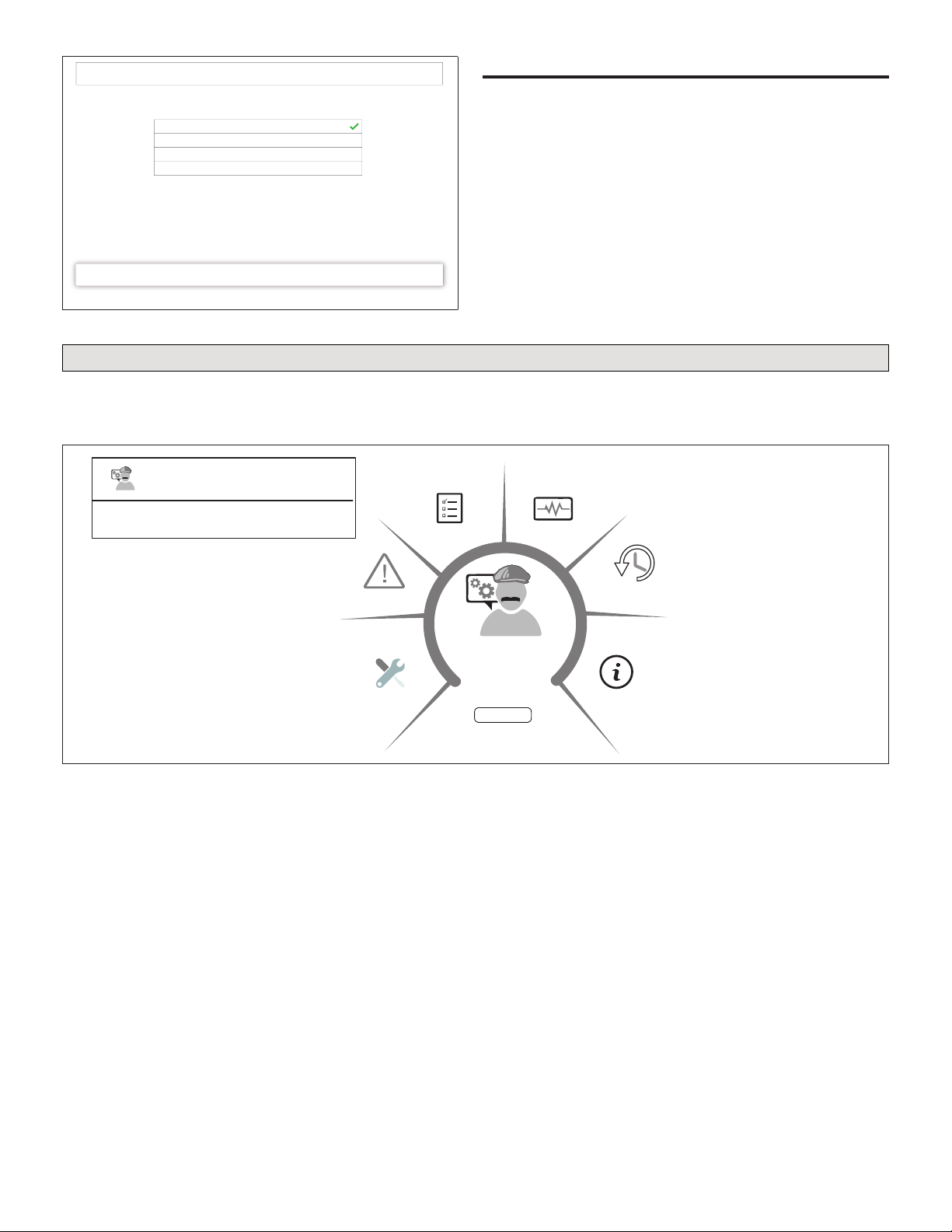
New features included are:
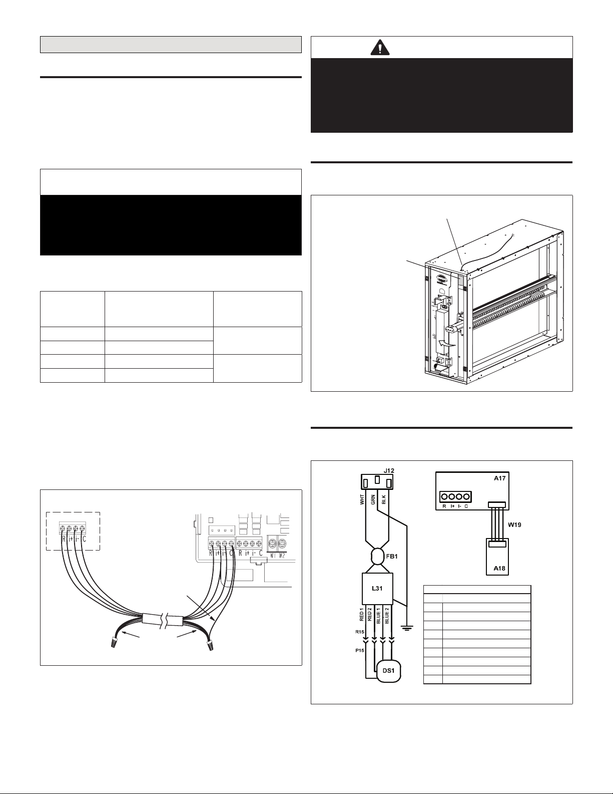
• 4-wire connection to Lennox communicating indoor
unit control
• Using sensors to:
> Automatically detect dirty air lter
> Display air lter life percentage
> Monitor UVA lamp operational state (On or Off).
> Display UVA lamp life percentage
IMPORTANT
Oil on metal ducts may cause odors.
Use a mild soap and water solution to remove oils from
transitions and duct surfaces prior to installation.
IMPORTANT
Do not use any form of silicone sealant.
Use of silicone-based products will reduce the
effectiveness of, or damage the titanium dioxide coatings
on the PCO cartridge.
IMPORTANT
Route power cord away from trafc areas where the cord
may become a safety hazard.
IMPORTANT
UVA lamp life is shortened when lamp is turned off and on.
Power to unit must remain on at all times.
Do not interlock lamp operation with air handler blower
operation.
CAUTION
Ultraviolet (UVA) radiation risk.
Prolonged exposure may cause skin or eye damage.
Avoid prolonged (weeks) exposure to skin or eyes.
WARNING
Risk of carbon monoxide poisoning.
Can cause injury or death.
Do not operate system unless access panel is in place
and properly secured. Operation of this equipment without
the access panel in place may cause exhaust fumes to be
drawn into occupied spaces.
CAUTION
Sharp edges hazard.
Sharp edges can cause injuries.
Use protective gloves when grasping equipment edges.

3
Parts Identication, Dimensions and Specications
Parts IdentIfIcatIon
Power Cord Opening
UVA Lamp Viewer
A
ccess Panel
UVA Lamp
UVA Lamp Light Sensor
UVA Lampholder /
PCO Cartridge
UVA Lampholder /
PCO Cartridge Rear
Mounting Bracket
Healthy Climate Carbon
Clean 16 Air Filter
Cabinet
Communication Control
UVA Lamp Electrical Connector
UVA Lamp Ballast
Figure 1. Parts Identication
dImensIons
top for bottom.
8-3/4
(222)
11/16
(17)
1-3/4
(33)
1-3/4
(33)
1-5/16 (33)
1-5/16 (33)
INLET AND OUTLET
OPENING
SAME SIZE
A
B
C
D
1
AIR FLOW
Power
Connection
UVA Lamp
Sight Glass
1NOTE - Airflow may be reversed by rotating the unit
E
Model No.
AB CDE
inches mm inches mm inches mm inches mm inches mm
PCO3S-14-16 23-3/4 603 23 584 20-1/4 51421-1/8537 18-1/2 470
PCO3S-16-16 26-1/2 673 25-3/4 654 23 58417-1/2445 14-5/8 371
PCO3S-20-16 26-1/2 673 25-3/4 654 23 58421-1/8537 18-1/2 470
Figure 2. Dimensions

4
sPecIfIcatIons
Table 2. Specications
Model Weight
(lbs.) Electrical Power
Consumption
Operating
Environment
Pleated Filter
Efciency Listings
PCO3S-14-16 24
120V, 50/60 Hz, 0.48 Amps
-- Maximum
or
230 V, 50/60 Hz, 0.24 Amps
-- Maximum
120VAC and
230VAC - 58
Watts Nominal
0°F to 140°F outside
of duct
10 to 60 percent relative
humidity
(Optimal performance
at 50 percent relative
humidity)
Minimum
Efciency
Rating Value
(MERV) 16
ETL safety listing
report 3061144A.
Conforms to UL
STD 1598
Certied to CSA
STD C22.2 no.
250.0.
PCO3S-16-16 27
PCO3S-20-16 27
Table 3. Approximate Air Flow Resistance
(Cabinet and Filter)
Capacity
(Tons)
Flow Rate
(CFM)
Pressure Drop (in. w.g.)
PCO3S-14-16 PCO3S-16-16 PCO3S-20-16
Low /
Variable 400 0.05 0.04 0.03
Low /
Variable 600 0.07 0.07 0.06
2800 0.11 0.11 0.08
2.5 1000 0.15 0.15 0.11
3 1200 0.20 0.20 0.15
3.5 1400 0.25 0.25 0.18
4 1600 *0.31 0.22
4.5 1800 * * 0.27
5 2000 * * 0.31
*Not recommended. Excessive system pressure drop can damage
HVAC system and reduce performance.
IMPORTANT
Do not wash UVA Lampholder / PCO cartridge. Soap
and water will destroy the titanium dioxide catalyst that
coats the cartridge surface.
IMPORTANT
Unpacking required.
Remove all protective packing material from the UVA
lamp (taped to the cabinet) and the titanium dioxide
PCO cartridge.
Packing material should be disposed of properly.
IMPORTANT
Possible odor emissions. Chemical reactions may
cause temporary odors after initial start-up or after lamp
replacement. Odor may also be present after paint,
cleaning solutions or hobby materials have been used in
the conditioned space.
Some occupants may experience irritation or discomfort
during this period. If the irritation or discomfort lasts
longer than 48 hours, the homeowner should be advised
to contact a Lennox dealer.
IMPORTANT
The cabinet should be installed so that the UVA lamp will
be in the horizontal position.
IMPORTANT
This system is NOT intended to be used for removal of
active mold growth or continuous sources of high levels
of chemicals in the air.
For existing mold growth, the mold must be properly
removed PRIOR to installation of the PureAir S air
purication system.
IMPORTANT
This appliance is intended for return air duct installation
only.
Improper installation may damage PureAir S air
purication system, HVAC system, or other equipment
and may also void warranty.
CAUTION
UVA Lamp contains mercury.
Ingestion of or contact with mercury or mercury vapor is
hazardous to your health.
Take care when handling UVA lamp. If UVA lamp is
broken, avoid contact with mercury.
IMPORTANT
Healthy Climate® Carbon Clean 16®Filter cannot tolerate
direct exposure to UVA light.
Filter is protected by PCO cartridge shield.

5
Installation Examples
UPFLOW FURNACE/AIR HANDLER
(Bottom Return Air)
DOWNFLOW FURNACE/AIR HANDLER
UPFLOW FURNACE
(Side Return Air − up to 4 ton)
UPFLOW FURNACE
(Option 1 − Side Return Air − 5 ton)
(With Optional RAB Return Air Base)
UPFLOW FURNACE
(Option 2 − Side Return Air − 5 ton)
(Modified Return Air Opening)
RETURN DUCT
SUPPLY DUCT
DUCT TRANSIITON
(Field Furnished)
FURNACE OR
AIR HANDLER
PCO3S
RETURN
DUCT
SUPPLY
DUCT
OPTIONAL
RAB RETURN
AIR BASE
PCO3S
RETURN
DUCT
SUPPLY
DUCT
PCO3S
RETURN
DUCT
SUPPLY
DUCT
PCO3S
RETURN
DUCT
SUPPLY
DUCT
PCO3S
NOTE: Lennox badge can be rotated 180 degrees
for this application.
HORIZONTAL FURNACE/AIR HANDLER
NOTE: Lennox badge can be rotated 180 degrees
for this application.
Figure 3. Installation Examples

6
Installation
UnIqUe fIeld-sUPPlIed InstallatIon Items
The following items are recommended to have on-hand for
installation of the unit.
• Cotton gloves and cloth (to remove nger prints from
UVA lamp)
• Aluminum foil tape or water-based mastic (NOT sili-
cone) to be applied as a sealant.
selectIng locatIon
The unit must be installed in the return air duct upstream of
the supply blower. Allow a 30” (76cm) service clearance in
front of the access panel as shown in gure 4. The air lter
and UVA Lampholder / PCO cartridge must be removable.
Allow Approximately
30” (76cm) of Clearance
Figure 4. Service Clearance
InstallIng cabInet
The cabinet may either be installed on a level installation
deck or platform adjacent to the air handler or it may be
suspended from the rafters using metal strapping. If straps
are used, take care when attaching straps to the cabinet.
Ensure fasteners do not interfere with internal components
of the cabinet. The air lter and UVA Lampholder / PCO
cartridge must be able to slide freely into the cabinet.
1. Locate and remove the UVA Lampholder / PCO cartridge
from the cabinet.
NOTE: Oil on metal surfaces may cause odors. Use mild
soap and water solution to wash all new duct and
transition surfaces.
2. Use the air ow directional label on the inside of the UVA
Lampholder / PCO cartridge to orient the unit.
3. Properly position the cabinet next to the return air
opening of the air handling unit. Use sheet metal screws
1” (25mm) maximum length, rivets or other appropriate
fasteners to secure cabinet to the return air side of the
air handling unit.
4. Use eld-provided sheet metal screws 1” (25mm)
maximum length to fasten the return air duct to the other
side of the cabinet. Attachment holes are provided in
housing.
5. Use eld-provided aluminum foil tape or water-based
mastic to seal all joints between the cabinet, air handler
and duct.
6. In high humidity applications, wrap cabinet with eld-
provided 2” (50mm) foil-faced insulation (foil on the
outside) to prevent condensation.
InstallIng UVa lamP
Use cotton gloves or a cotton cloth to protect the lamp and
your hands during unpacking and installation.
1. Remove cabinet access panel.
2. The UVA Lampholder / PCO cartridge is shipped in a
protective packaging. Packaging must be removed
prior to installation. Take care to prevent damage while
removing from packaging.
3. Locate the UVA lamp box, which is taped to the inside of
cabinet and carefully remove. Set UVA lamp box aside
while preparing cabinet for UVA lamp installation.
4. Remove (slide out) Healthy Climate® Carbon Clean 16®
Filter from cabinet.
5. Disconnect the lampholder cable assembly from the
UVA lamp ballast connector.
6. Carefully remove lamp from UVA lamp box and secure
the UVA lamp electrical connector to the UVA lamp by
sliding the UVA lamp pins into the slot. Proper connection
will make a snapping sound.
DEPRESS RED BUTTON
ONLY TO RELEASE UVA
LAMP FROM SOCKET.
Figure 5. Releasing UVA Lamp from Socket
7. Slide the UVA lamp into UVA Lampholder / PCO
cartridge. Verify that the UVA lamp is secure to the one
metal UVA lamp clamp located mid-way on the UVA
lamp reector.
METAL UVA LAMP
CLAMP
UVA LAMP REFLECTOR
Figure 6. UVA Lamp Metal Clamp

7
8. Rotate the hinged control panel assembly out.
ROTATE OUT THE
CONTROL PANEL
ASSEMBLY
Figure 7. Rotate Out Control Panel Assembly
9. Thread the UVA Lampholder / PCO cartridge two posts
through the UVA lamp connector’s two holes.
10. Fasten the lamp socket to the UVA Lampholder / PCO
cartridge using the two-brass nger nuts located in the
literature bag.
BRASS FINGER
NUTS
A
IRFLOW
INDICATOR
WING
NUTS
Figure 8. Brass Finger and Wing Nuts
InstallIng UVa lamPholder
Use the following procedure to install the UVA Lampholder
/ PCO cartridge.
1. While aligning, slide the UVA Lampholder / PCO
cartridge into case rails and align with rear mounting
bracket.
2. Secure the UVA Lampholder / PCO cartridge to the two
frame screw posts using the provided wing nuts (2).
NOTE: There is an arrow on the front of the component
indicating the correct way to install it.
3. Connect UVA lamp 4-pin male connector to ballast
female 4-pin connector.
BALLAST FOUR PIN
FEMALE CONNECTOR
LAMPHOLDER
ASSEMBLY
(Y6622)
Figure 9. Ballast 4-Pin Female Connector
4. Rotate hinged control panel assembly back into the
cabinet. Make sure no wiring is being pinched.
InstallIng aIr fIlter
Use the following procedure to install the air lter.
1. Slide the Healthy Climate® Carbon Clean 16®Filter into
the rails on the air inlet side of the cabinet. Verify proper
airow direction.
2. Securely fasten the access panel.
3. Plug one end of the provided power cord into the
receptacle on the cabinet and the other end into a power
receptacle.
4. Look through the view port in the access panel to check
that the UVA lamp is illuminated.
NOTE: On initial start-up, the UVA lamp may not reach full
illumination for several minutes.

8
Wiring
termInals and WIrIng recommendatIons
Communicating systems requires four thermostat wires
between the PureAir S and the Lennox Communicating
Indoor Control. When a thermostat cable with more
than four wires is used, the extra wires must be properly
connected to avoid electrical noise. The wires must not be
left disconnected. See “Figure 10. Communicating and Low
Voltage Connections”.
IMPORTANT
Use 1-pair, 18AWG unshielded thermostat cable (eld-
provided) for power terminals (R and C). We highly
recommend using 18 - 22AWG shielded thermostat cable
for communications terminals (I+ and I-) which will help
eliminate any noise interference.
Table 4. Terminal Designations and Wiring
Recommendations
Terminal
Designation Description
Recommended
Thermostat
Wiring
R24VAC input 18AWG unshielded
C24VAC return
I+ RS-BUS I+ 18 - 22AWG
shielded
I- RS-BUS I-
• Use wire nuts to bundle the unused wires at each end of
the cable. A single wire should then be connected to the
indoor unit end of the wire bundle and attached to the “C”
terminals.
• Keep all communication wiring as far away from the
house electrical wiring and large electrical appliances as
possible. Recommended minimal distance is 15 feet (5
meters).
Unused wires
Single wire
to terminal “C”.
Indoor Unit Controller
PureAir S
Figure 10. Communicating and Low Voltage
Connections
IMPORTANT
Do not connect low voltage wiring to the PureAir Suntil you
conrm the S30 thermostat has thermostat / Smart Hub
control software version 03.40.xxxx or higher software.
To update S30 thermostat follow the check for update
procedures outlined in service and application note ACC-
18-05.
commUnIcatIon WIrIng roUtIng
Communication wiring to the indoor unit is routed through
the opening in the top of the cabinet as illustrated below.
Route communication wiring through
grommet to indoor unit
iComfort Communicating
PCO Control
Figure 11. Routing of Communication Wiring
PUreaIr SInternal factory WIrIng
The should be wired in accordance with national and local
codes.
KEYCOM PONENT
DS1UVA LAMP / LAMPHOLDER
P15PLUG
R15REC EPTACLE
L31BALLAST
J12JACK
FB1FERRI TE BEAD
A17MAIN SENSOR BOARD
A18UVA SENSOR BOARD
W19INT ERCONNEC T WIRE
LEGEND
Figure 12. PCO Wiring Schematic

9
Communicating Control Functions
UV Lamp Sensor Control
Board
Pushing and Holding the Change Filter buon or the Change Lamp buon for 5 seconds will reset the control
Change Filter
buon
Lamp sensor control board
ribbon connecon
High side pressure tap
Low side pressure
tap
Change Lamp
buon
iComfort wiring
connecons
PCO unit size
selecon jumper
C
h
b
u
Filter Control Board
Figure 13. PureAir S Communicating Control
Pco model (h2) JUmPers
A series of jumpers is used to select which size pure air the
control is installed.
Jumper selections are:
• Position 1 (pins 1 and 2 shorted): 14-16 (nominal airow
= 1400cfm)
• Position 2 (pins 2 and 3 shorted): 16-16 (nominal airow
= 1600cfm)
• Position 3 (pins 3 and 4 shorted): 20-16 (nominal airow
= 2000cfm)
NOTE: The correct size selection should already be set
from the factory.
14-16
Jumper Setting
16-16
Jumper Setting
20-16
Jumper Setting
Jumper
Figure 14. Model Jumper Selection
change lamP reset (sW1)
After bulb replacement, press and hold for three seconds
SW1 - Change Lamp button. This resets the system.
A LED will start to ash after three seconds to indicate the
reset was successful.
change fIlter reset (sW2)
After air lter replacement, press and hold for three seconds
SW2 - Change Filter. This resets the system.
A LED will start to ash after three seconds to indicate the
reset was successful.
control manUal reset
When pressing both the SW1 and SW2 switches at the
same time for ten seconds will reset the control to factory
default.
Control can also be reset by using the S30 thermostat. Go
to menu > settings > advanced settings > view dealer
control center > equipment > reset > reset HVAC
equipment.
Lennox S30 Thermostat Setup
system setUP (commIssIonIng)
During the initial or rerunning the commissioning of the
system using the iComfort S30 Ultra Smart thermostat, the
system will auto-detect the presence of the PureAir Sunit.
Follow the instructions provided with the thermostat for the
system commissioning process. If the PureAir Scomponent
is successfully detected, it will appear on the found
equipment screen.
NOTE: During commissioning the blower will turn on and
run at three different CFM settings for the PCO
lter calibration to take place. This may be well in
advanced before the display is fully up and running.
This is a normal process. The blower may run as
long as 90 seconds at each CFM setting to complete
the lter calibration .
equipment found
welcome to iComfort
previous continue
system
+/-
Thermostat
104553-01
Heat Pump
XP25-060-230
PureAir
PCO3S16-16
Smart Hub
Air Handler
CBX40UHV-060; 1
non-communicating
equipment
Mag-Mount
1045498-01
Figure 15. Equipment Found
remInders
Default setting is sensor-based. Additional options are
calendar time, run-time or disabled. On the reminder screen,
select PureAir S maintenance to change the option.

10
disabled
Please verify or modify reminder settings.
done
PureAir maintenance
calendar time
sensor-based
run-time
Figure 16. PureAir S Maintenance Setting
addIng PUreaIr S to exIstIng system
Once the PureAir S accessory has been installed and
system powered up, go to the thermostat. From the
thermostat to go to menu > settings > advanced settings
> view dealer control center > equipment and select
reset. From the reset list, select re-congure system. This
will tell the system to reboot and search for new equipment
attached to the system.
Follow the commissioning screens to the equipment
found screen, verify that the PureAir S accessory has
been detected and added to the system (see “Figure 15.
Equipment Found” on page 9).
NOTE: The Lennox S30 thermostat must have rmware
version 3.4 or later for compatibility with Lennox
Pure Air S Air Purication System.
Dealer Control Center
The Dealer Control Center menu provides access for the
installer or service technician to perform various functions.
Advance equipment congurations, notications, tests,
diagnostics, installation reports and general information
about the system. Go to menu > settings > advanced
settings > view dealer control center.
dealer
control center
equipment
tests
notifications
information
diagnostics
exit
Use to make changes to equipment settings and add or remove
non-communicating equipment or accessories. In addition the reset all
equipment option is available. This will allow the installer to reset all
equipment and reconfigure.
Use to display
system notifications
Use to run test on
system components
Use to run
diagnostics on
system components
Use to display
system information
Exit to Home
screen.
To navigate back to the dealer control center,
touch on the Dave Lennox icon when available
on the top left-hand side of the screen.
<
<To navigate back to the previous screen, touch
on the left arrow when available.
“Previous Screen
Name”
installation
report
Used to display installation results.
NOTE: This report is not available until after
exiting the dealer control center following the
commissioning procedure. Exit and return to
the dealer control center to view the installation
report.
Figure 17. Dealer Control Center

11
PUreaIr SeqUIPment Parameters
The following is a complete list of all possible parameters listed under System. Parameters actually available are dependent
on the Lennox communicating equipment type detected and non-communicating equipment added.
From the Dealer Control Center Screen, go to equipment > PureAir. There you will nd the applicable parameter settings
for PureAir S.
Table 5. PureAir S Parameters
Parameter Description
Equipment PureAir Filter
Dirty Filter and UV
Life Detection
Default: ON. Options are either ON or OFF. Alarms 503 and 504 will not be displayed when this parameter is set
to OFF. The diagnostics screen on the thermostat will continue to show values for both lter life and UV lamp life
regardless of the value of this parameter.
• This parameter turns on and off the lter life and UV lamp life reporting. When set to off, the control will continue to
calculate the remaining lter life through continuous sampling, but will not use lter tests to determine lter life. The
control will:
• Perform a UV lamp calibration upon indication of a lamp change regardless of the value of this parameter.
• Will calculate UV lamp life remaining regardless of the value of this parameter.
Max Air Filtered
between Tests
Default is 100%, Range is 50% to 100% Changes can be made in increments of 10%.
This parameter modies the amount of air that is allowed to pass through the lter after a valid % life determination
before a lter test is initiated.
This parameter is expressed as a percentage of the cubic feet of air that would pass through the lter if the fan
operated at continuous fan CFM for 30 days.
UV lamp operation
detection Default: ON. Options are either ON or OFF.
Filter Life Provides percentage of remaining lter life. This is for display purposes only and cannot be changed.
Last replacement
date for lter Date last lter reset was accomplished. This is for display purposes only and cannot be changed
Purier life Provides percentage of remaining purier life. This is for display purposes only and cannot be changed
NOTE: Purier life is referring to the UVA Lamp / PCO cartridge insert.
Last replacement date
for purier insert Date last purier insert reset was accomplished. This is for display purposes only and cannot be changed
• reset PureAir S will reset all PureAir S parameters back to factory defaults.
• reset purier insert will reset (recalibration) it to 100%. This is usually accomplished after the UVA Lamp / PCO cartridge insert has been replaced.
• reset lter will reset (recalibration) it to 100%. This is usually accomplished after the air lter has been replaced.
notIfIcatIons (alert codes)
The thermostat’s notication screens provide information
on active notications and previously cleared notications.
When selecting either a cleared or active notication a brief
description and alert code will be displayed. Notications are
categorized by system, indoor unit (air handler or furnace),
outdoor unit (air conditioner or heat pump), zoning control (if
installed) and thermostat.
tests and dIagnostIcs fUnctIon
There are no installer tests or diagnostic features available
for the PureAir S accessory.
InstallatIon rePort
PureAir S accessory information includes equipment name,
model number, serial number and rmware version.
In addition, when selecting PureAir S, lter life, last
replacement date for lter and purier life and last
replacement date for purier information is available.
System
Air Conditioner
PureAir S
Air Handler
installation report
model number
software version
serial number
PCO3S14-16
123456
00.03.0400
name
Equipment Name PureAir Filter
Dirty Filter Detection and UV life Detection On
Max Air Filtered between Tests 100.0%
UV lamp operatoin detection
Filter life 100%
Installation date for filter 3/1/2018
PureAir S
On
3/02/2018
overview
Figure 18. Installation Report

12
Alert Codes
soft dIsable
Soft disabling is when the thermostat nds an unknown control on the system communication bus. The thermostat sends
the unknown control a message to go into soft disable mode until the component is properly congured or removed.
The thermostat will not show any code for a soft disabled control. When soft disabling occurs only the control that has
been disabled will display the blinking LED status. Refer to the device’s installation and setup guide for further guidance.
Conrm proper wiring between all devices such as thermostat, PureAir S and Smart Hub.
Cycle power to the PureAir S.
1. Go to the menu > settings > advanced settings > view dealer control center. Touch proceed to continue.
2. Select equipment.
3. Touch reset.
alert code tyPes
To expand a specication notication to access a more detail description of the alert code, press the down arrow to expand
the description.
• Service Urgent alerts are displayed on Home (user) screen under the homeowner and installer alert buttons. Service
Urgent means that a service call is needed to get the system running.
• Service Soon / Service Urgent means that the system will likely recover on its own and no interaction is necessary.
Typically, either after a specic timer period or a specic number of instances, some Service Soon alerts will escalate
to Service Urgent.
• Service Soon alerts are found only in under the installer alert button.
• Information Only-Dealer is information only and helps Lennox interpret test results and understand complicated
behaviors. Information Only are not reported to homeowner or dealer.
NOTE: Communication System: When communication controls are operating in a communication system, all jumpers
and links setting on the controls are ignored. Jumpers and links setting are treated as defaults and would only be
active if the system was congured as a non-communicating system.

13
•
Table 6. Alert Codes and Troubleshooting
GF= Gas Furnace, AH=Air Handler, ID=Indoor unit (GF or AH), HP=Heat Pump, AC=Air Conditioner, OD=Outdoor Unit (AC or HP), PA=Pure Air S,
ZA=Zone system and TS=Thermostat
Alert
Code
Priority
Condition
Actual Displayed
Alert Text
Under dealer
control center >
Notications
Component or System Operational State
and Troubleshooting Tip How to clear alert code
105 Service
Urgent
Communication
Problem
One of the system components has lost communication with
the system. The system component (device) is unable to
communicate.
• S30 - Access dealer control center, select notications icon,
review alert code details to determine which device or unit has
the communication problem. Review both active and cleared
alerts.
• Wi-Fi – Press and hold the Lennox logo on the bottom right of
stat for 5 seconds to access the dealer control center. Follow the
prompts to access the dealer / installer screen and select the
“Alerts” tab. Review alert code details to determine which device
or unit has the communication problem. Review both active and
cleared alerts.
• Zoning - Remove wire from smart hub to iHarmony control and
just have wiring from furnace.
Troubleshooting:
• Check each control for additional codes
• In most cases issues are related to electrical noise. Verify that high
voltage power is separated from the low voltage communication
wires.
• Check for proper grounding on line voltage and low voltage
wiring, transformer and equipment.
• Check for incorrectly wired or loose or spliced connections
between system components (devices or units).
• Make sure all unused wires are tied together and taken back
to the C terminal on the indoor control board as shown in the
installation and setup guide.
• Disconnect all wiring to other system components (except
thermostat to indoor unit) and reconnect one device at a time and
recommission system each time a device is reconnected until the
issue is located.
• Zoning: If zoning is installed and is wired directly from smart hub
to iHarmony control then disconnect that wiring. Run control
wiring from the iHarmony control directly to the indoor unit control.
Wiring diagrams are provided in the iHarmony Installation and
Setup Guide.
• Float Switch: When using a oat switch, use isolation relay to
break common wire to outdoor unit. For testing purposes, remove
oat switch from the circuit.
• Firmware and Accessories: Make sure that smart hub has
correct rmware version for added accessory. (Example: Pure
Air S and/or Apple Home Kit must have software version 3.4 or
higher before it will connect to system properly. (If software is not
updated in system it will cause system operation issues).
• Inductive voltage from surrounding sources. Check each wire in
AC mode to C on circuit board.
> Good voltage is .03-.3VAC inductive voltage is not an issue.
> Acceptable can be up to .7VAC with moderate success.
> Some units have worked with up to 1.2VAC with occasional
success.
> Voltage over 1.2VAC needs to be addressed.
Automatically clears when the
system detects the issue no longer
exists.

14
Table 6. Alert Codes and Troubleshooting
GF= Gas Furnace, AH=Air Handler, ID=Indoor unit (GF or AH), HP=Heat Pump, AC=Air Conditioner, OD=Outdoor Unit (AC or HP), PA=Pure Air S,
ZA=Zone system and TS=Thermostat
Alert
Code
Priority
Condition
Actual Displayed
Alert Text
Under dealer
control center >
Notications
Component or System Operational State
and Troubleshooting Tip How to clear alert code
120 Service Soon Unresponsive
Device
There is a delay in the system component responding to the
system. Typically this alert code does not cause any operational
issues and will clear on its own.
• This alert code is usually caused by a delay in the outdoor unit
responding to the thermostat.
• Leaking voltage from strands within the bundle.
> Land only the R wire on the Rterminal to load the bundle with
24VAC.
►Typically only the Rwire needs to be landed to identify if
voltage is leaking.
►If voltage is present checking the other wires is informational
only but not needed.
►If voltage is not present checking the other wires one at a
time would be needed.
> Check each loose wire in AC mode to Con circuit board.
► Good voltage is .03 -.3VAC leaking voltage is not the issue.
►Acceptable can be up to .7VAC with moderate success.
► Some units have worked with up to 1.2VAC with occasional
success.
► Voltage over 1.2VAC needs to be addressed.
Automatically clears after an
unresponsive system component
(device) responds to any inquiry.
124 Service
Urgent
Tstat Lost
Communication
To Smarthub
The thermostat has lost communication with a system component
for more than three minutes. System component has lost
communication with the thermostat.
• Check the wiring connections between components.
• Ohm wires.
• Cycle power.
• Any component that is miss-wired may cause a false component
code to be shown on system component.
• Disconnect all wiring to other system components and check
communication one at a time.
NOTE: When using a oat switch, use isolation relay to break
common wire to outdoor unit. For testing purposes, re-
move oat switch from the circuit
This alert code stops all associated system operations and waits
for a heartbeat message from the system component that is not
communicating.
Automatically clears after
communication is re-established
with applicable system component
(device).
125 Service
Urgent
Control
Hardware
Problem
There is a hardware problem on a system component control.
There is a control hardware problem.
• In system using iHarmony zoning, the system will remain in
non-zone mode (all dampers open) for ve minutes after priority
condition no longer exist.
• In systems using a Equipment Interface Module, remove jumper
if present on indoor unit between Rand W2.
• In systems using a PureAir S, the pure air control board jumper
selector is missing.
If none of the above tips are applicable, then replace the control if
the problem prevents operation and is persistent.
Automatically clears ve minutes
after the issue no longer exists.
126 Service
Urgent
Control Internal
Communication
Prob
There is an internal hardware problem on the system component
control. In addition, if you have zoning the alert code is triggered
when your zone temperature is deviating away from set point
persistently.
• Typically the system component control will reset itself.
• Replace the system component (device) control if the problem
prevents operation and is persistent.
Automatically clears 300 seconds
after the issue no longer exists.

15
Table 6. Alert Codes and Troubleshooting
GF= Gas Furnace, AH=Air Handler, ID=Indoor unit (GF or AH), HP=Heat Pump, AC=Air Conditioner, OD=Outdoor Unit (AC or HP), PA=Pure Air S,
ZA=Zone system and TS=Thermostat
Alert
Code
Priority
Condition
Actual Displayed
Alert Text
Under dealer
control center >
Notications
Component or System Operational State
and Troubleshooting Tip How to clear alert code
132 Service
Urgent
Device Control
Software Fault
System component control software is corrupted.
• Recycle power.
• If failure re-occurs, replace the system component control.
Manual system power reset is
required to recover from this alert
code.
500 Service Soon
PA Differential
Pressure Sensor
Fault
• Pressure sensor reports a fault for more than 5 minutes, or does
not respond for more than 5 minutes.
• Device will not perform any pressure reading calculations until
fault is recovered. Remaining lter life display will indicate “-“
while fault exists.
Automatically clears 30 seconds
after fault is recovered.
501 Service Soon PA UV Sensor
Fault
• Ultra-violet (UV) sensor reports a fault for more than 5 minutes or
UV sensor does not respond for more than 5 minutes.
• Device will not perform any UV lamp life remaining calculations
until fault has recovered. Life remaining display shall indicate “-“
while fault exists.
Automatically clears 30 seconds
after fault is recovered.
502 Service Soon PA UV Lamp Off The light is determined to be off when the last three last light
intensities measurements are below the set threshold.
Light is determined on after 1 set
of ve samples are above the set
threshold.
504 Service Soon PA Filter Life
At 0% Filter life remaining determined to be 0%. None
505 Service Soon
PA Model
Selection
Changed
Model Selection jumper has changed positions.
Jumper repositioned back to
original jumper position or system
rebooted.
506 Service Soon PA Lamp At 0%
life Ultra violet lamp life is at 0%. None
507 Service Soon
PA Filter
Calibration
Failure
• Filter calibration determined failed due to all test cfm static
pressures reading <= 7 Pa.
• Send alert code immediately.
• No lter tests or life calculation occur while this alert code is
active.
Clear alert code upon initiation of
another lter calibration.
-- Service Soon --
Possible loose or mis-wired connections or two zone sensors are
assigned the same zone number. Two dashes will be displayed
on the S30 thermostat for indoor temperature and/or zone sensor.
The system will go into central mode. Individual zone functions
is disabled. Anytime the zone sensor loses communication with
the damper control module, the entire system will go into central
mode. If two sensors are assigned the same zone number, this
could result in the double dashes to appear as well.
If two zone sensors are assigned
the same zone number, this could
cause the double dashes to appear.
If loose or mis-wired connection was
conrmed, correct the issue and run
the re-conguration procedure.

16
Operation
1. Check to ensure that access panel is securely in place.
2. Lamp should remain illuminated continuously except
during service and maintenance.
3. For optimal odor control, air handler blower should
remain on CONTINUOUSLY (thermostat fan setting in
ON position, rather than AUTO).
NOTE: If air handler does not provide a continuous low
blower speed option, an additional blower relay
should be installed. Use Lennox part number
45H03. Contact the Lennox Application Department
at 1-800-453-6669 for wiring information.
NOTE: Continuous fan operation may result in higher
humidity. If humidity levels are uncomfortably high,
fan setting should be switched to AUTO during
cooling operation.
Filter, UVA Lampholder / PCO Cartridge and
UVA Lamp Replacement
IMPORTANT
Hg -- UVA Lamp contain mercury.
Manage in accord with disposal laws.
Refer to www.lamprecycle.org or call 1-800-9LENNOX.
The Healthy Climate® Carbon Clean 16®Filter, UVA
Lampholder / PCO cartridge and UVA lamp require annual
replacement. More frequent lter replacement may be
required in applications with heavier dust or dirt loads or if
you notice a reduction in odor-removal efciency. An annual
maintenance kit is available.
Annual Maintenance Kits
The annual maintenance kits include the following:
• Healthy Climate® Carbon Clean 16® Filter (1)
• PCO cartridge (1)
• UVA lamp (1)
Order using the following kit catalog numbers:
Table 7. Maintenance Kits
Part
Description
Catalog Numbers
PCO3S-14-16 PCO3S-16-16 PCO3S-20-16
Annual
Maintenance
Kit
Y6616 Y6612 Y6608
Replacement Parts
Replacement parts are available through Lennox, see
“Figure 1. Parts Identication” on page 3 for parts
arrangement. Part description and catalog numbers are as
follows:
Table 8. Repair Parts
Part Description Catalog Numbers
PCO3S-14-16 PCO3S-16-16 PCO3S-20-16
HC Carbon Clean
16 Filter Y6606 Y6605 Y6604
UVA Lamp X8794
PCO cartridge
insert (Purier) Y6621 Y6607
Lampholder
Assembly Y6622
Power Cord
(120VAC) 49M48
Power Cord
(230VAC) 91X44
Electrical Socket 75X77
Ballast Y6620
Probe Repair Kit 16X01 16X02 16X01
Sensor Repair Kit 16X03

17
remoVIng and InstallIng UVa lamP, lamPholder and
aIr fIlter
IMPORTANT
If the system has been operated for a period of time
without the UVA lamp being illuminated, an odor may
occur when lamp is illuminated. This odor is considered
typical and should dissipate within 12 hours of full
operation. If the odor does not subside after 48 hours
of operation, instruct the homeowner to unplug the unit
and contact a Lennox dealer.
CAUTION
Personal Burn Hazard.
UVA lamp is very hot when illuminated.
Allow lamp to cool for 10 minutes before removing lamp
from socket.
Injury may result from contact with hot UVA lamp.
1. Remove power cord from 120VAC or 230VAC
receptacle.
2. Remove power cord from unit.
3. Remove access panel.
4. Remove Healthy Climate® Carbon Clean 16®Filter.
5. Rotate out the hinged control panel.
6. Disconnect UVA lamp electrical connector from ballast.
7. Remove both fasteners securing the UVA Lampholder /
PCO cartridge from the chassis.
8. Slide out the UVA Lampholder / PCO cartridge from the
chassis.
9. Remove both brass nger nuts that secure the UVA
lamp elector connector to the UVA Lampholder / PCO
cartridge.
10. Slide out UVA lamp from UVA Lampholder / PCO
cartridge insert.
11. Push the red button on UVA lamp electrical connector
and gently slide off connector from UVA lamp (do not
dispose of UVA lamp electrical connector).
12. Properly dispose of UVA lamp and air lter.
13. Reinstall in reverse order starting.
ProPer clean-UPof broken UVa lamP
If UVA lamp is broken, it must be disposed of properly.
• Wear protective gloves, eye wear and mask.
• Sweep broken glass and debris into a plastic bag and
seal before disposal in accordance with instructions
provided by local waste management ofce.
• Do not use a vacuum cleaner. Do not incinerate.

18
Troubleshooting Flow Chart
START Look through the access panel
viewing port to check lamp.
Is there power to the
PCO?
Is the lamp on?NO
Check PCO power cord for
damage and AC outlet for
power. Check breaker
panel. Repair electrical
problem and plug−in power
cord.
Is the lamp on?
Unplug power cord to
the PCO cabinet.
YES
Check lamp
electrical
connectors. Also check
electrical wiring from ballast
to lamp connector.
Any issues?
Plug power cord back
to the PCO cabinet.
NO
Repair Issues
Is the lamp on?
Check ballast voltages (see
table below) on red and blue
wires at 4−pin connector.
Replace any burned out or
damaged components.
NO
Is the lamp on?
NO
Continue with
maintenance per unit
installation instruction.
YES
YES
YES
NO
Is PCO power cord plugged
into AC outlet? If not, plug
PCO cord into AC Outlet.
Is the lamp on?
NO
YES
NO
YES
YES
BALLAST
INPUT/OUTPUT WIRE/TERM COLOR NORMAL READING (VAC) SERVICE ACTION (See “Figure 12. PCO
Wiring Schematic” on page 8.)
OUTPUT
RED >60 Replace ballast if less than 60VAC.
RED >60
BLUE >200 Replace ballast if less than 200VAC.
BLUE >200
Figure 19. Troubleshooting Flowchart

19

20
Other manuals for PureAir PCO3S-14-16
1
This manual suits for next models
2
Table of contents
Other Lennox Air Cleaner manuals

Lennox
Lennox PUREAIR PCO-12C Assembly instructions

Lennox
Lennox Healthy Climate PMAC-20C User manual

Lennox
Lennox PureAir PCO-12C-2 User manual

Lennox
Lennox Healthy Climate PureAir PCO-20P-2 User manual

Lennox
Lennox Air Filter User manual

Lennox
Lennox HEPA Bypass Air Filtration Systems HEPA-20 User manual

Lennox
Lennox Variable Speed Air Handler CBX40UHV User manual

Lennox
Lennox 91W54 User manual

Lennox
Lennox Air Purification System Pureair User manual

Lennox
Lennox Healthy Climate PMAC-12C User manual