Lennox 84W88 User manual

Page 1
HEAT PUMP UNITS
KITS AND ACCESSORIES Litho U.S.A.
504,587M
3/2014
Supersedes1/2013
REPLACEMENT DEFROST
CONTROL
INSTALLATION INSTRUCTIONS FOR REPLACEMENT DEFROST CONTROL KIT (84W88)
USED WITH VARIOUS HEAT PUMPS
WARNING
Improper installation, adjustment, alteration, service or
maintenance can cause personal injury, loss of life, or
damage to property.
Installation and service must be performed by a licensed
professional installer (or equivalent) or a service agency.
WARNING
Electric Shock Hazard. Can cause injury
or death. Unit must be grounded in
accordance with national and local
codes.
Line voltage is present at all components
when unit is not in operation on units with
single‐pole contactors. Disconnect all
remote electric power supplies before
opening access panel. Unit may have
multiple power supplies.
Shipping and Packing List
Package 1 of 1 contains:
1 - Defrost control (100269-05)
4 - 1/4” quick connect terminals
2 - Black wire
1 - Wire (1 foot in length)
1 - Defrost control replacement - information sticker
(401843S)
Application
Replacement defrost control kit (84W88) includes defrost
control 100269. This defrost control may be used in
various heat pump units to replace any defrost control
listed in table 1. The 100269 includes features which may
not be found in all of the existing controls. If the unit was
originally equipped with any defrost control other than a
100269 series, operation should be reviewed at the time of
replacement. Features of 100269 defrost control include:
Five-minute compressor anti-short cycle delay;
Pressure switch lockout circuit;
Loss of charge / low pressure switch circuit;
Field-selectable compressor delay
Field connection terminals for service light.
Table 1. Applicable Defrost Controls
Original Defrost Control Replacement Defrost Control
100269-01, -02 and -04
100269-05
29M0101
29M0201
56M3701
68J2901
68J8401
Defrost System
The defrost system includes a defrost thermostat and a
defrost control.
DEFROST THERMOSTAT
The defrost thermostat is located on the liquid line between
the check/expansion valve and the distributor. When the
defrost thermostat senses 42°F (5.5°C) or cooler, its
contacts close and send a signal to the defrost control to
start the defrost timing. It also terminates defrost when the
liquid line warms up to 70°F (21°C).
DEFROST CONTROL (CMC1)
The defrost control includes the combined functions of a
time/temperature defrost control, defrost relay, time delay,
diagnostic LEDs, and a terminal strip for field wiring
connections.
The control provides automatic switching from normal
heating operation to defrost mode and back. During
compressor cycle (defrost thermostat is closed, calling for
defrost), the control accumulates compressor run times at
30, 60, or 90 minute field adjustable intervals. If the defrost
thermostat is closed when the selected compressor run
time interval ends, the defrost relay is energized and
defrost begins.
Defrost Control Timing Pins (P1)
Each timing pin selection provides a different
accumulated compressor run time period for one defrost
cycle. This time period must occur before a defrost cycle
is initiated. The defrost interval can be adjusted to 30
(T1), 60 (T2), or 90 (T3) minutes (see figure 1). The
maximum defrost period is 14 minutes and cannot be
adjusted. Factory default is 90 minutes
If the timing selector jumper is missing, the defrost
control defaults to a 90-minute defrost interval.

Page 2
24V TERMINAL STRIP
CONNECTIONS
DIAGNOSTIC LEDS
HIGH PRESSURE SWITCH
TEST PINS
FIELD SELECT
TIMING PINS
REVERSING VALVE
DEFROST THERMOSTAT
LOW PRESSURE SWITCH
COMPRESSOR DELAY PINS
S4
S87
SERVICE LIGHT CONNECTIONS
Figure 1. Defrost Control (100269-05)
Test Mode
The TEST mode is activated by removing the jumper on
the defrost termination pins (30, 60 or 90) and placing the
jumper on the TEST pins after 24VAC is applied to the
control. The low pressure input is ignored in TEST mode.
IMPORTANT
The TEST pins are ignored and the TEST function is
locked out:
SIf the jumper is applied on the TEST pin before
24VAC is applied to the control.
SIf there is a jumper on the 30 or 60 minute defrost ter
mination pins.
Bypass-Anti-Short Cycle Delay
The Y1 input must be active ON, the high pressure switch
must be closed or a jumper must be installed on the high
pressure terminals of the control.
Initiate a Forced Defrost
The Y1 input must be active ON, the high pressure switch
must be closed or a jumper must be installed on the high
pressure terminals of the control, the defrost thermostat
must be closed or a jumper must be placed across the DF
terminals on the control and the Oterminals must not have
24VAC (no power to reversing valve) before control will
enter into a force defrost.

Page 3
Test Mode Sequence
Using the defrost termination pin, short the TEST pins for
a period of two seconds:
Clear timed lockout / or pressure switch lockout
function.
Enter defrost mode
After entering forced defrost, if the jumper is removed
before 5 seconds has elapsed, the unit will remain in forced
defrost mode until defrost thermostat opens or terminated
on maximum defrost time (14 minutes). If the jumper is not
removed, once 5 seconds has elapsed (7 seconds total),
the unit will terminate defrost and return to heat mode. The
TEST mode will then be lockedout and no further TEST
mode operation will be executed until the jumper on the
TEST pins is removed and reapplied to the applicable
defrost termination pins.
IMPORTANT
NOTE - After testing has been completed, properly re
position test jumper across desired timing pins.
Compressor Delay (P5)
The 10026905 control, with the 30 second field
selectable delay, is active when the pins are jumpered.
This feature helps reduce occasional sounds that may
occur while the unit is cycling In and Out of the defrost
mode.
NOTE — The 30‐second compressor feature is ignored
when jumper is installed on TEST pins.
Compressor Anti-Short-Cycle Delay
The timed-off delay is five minutes long. The delay helps
protect the compressor from short-cycling in case the
power to the unit is interrupted or a pressure switch opens.
The delay is bypassed by placing the timer select jumper
across the TEST pins for 0.5 seconds.
NOTE - The defrost control must have a thermostat
demand for the bypass function to operate
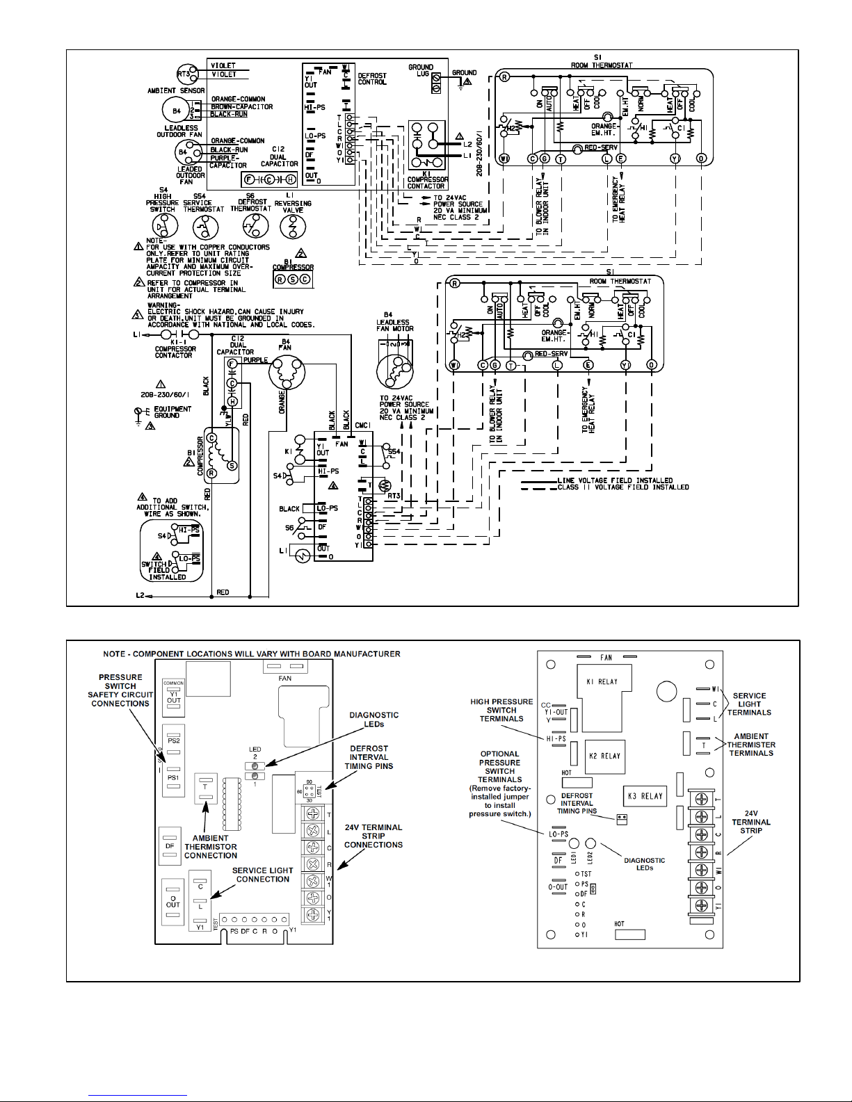
Pressure Switch Circuits
The defrost control includes two pressure switch circuits.
The factory-installed high pressure switch (S4) wires are
connected to the defrost control's HI PS terminals (figure
1). The defrost control also includes LO PS terminals to
accommodate an optional field-provided low (or
loss‐of‐charge) pressure switch.
During a single thermostat cycle, the defrost control will
lock out the unit after the fifth time that the circuit is
interrupted by any pressure switch that is wired to the
defrost control. In addition, the diagnostic LEDs will
indicate a pressure switch lockout after the fifth occurrence
of an open pressure switch (see table 1). The unit will
remain locked out until 24V power from the indoor unit is
broken then remade to the control or until the jumper is
applied to the TEST pins for 0.5 seconds.
NOTE - The defrost control ignores input from the low
pressure switch terminals during the TEST mode, during
the defrost cycle, during the 90-second start-up period,
and for the first 90 seconds each time the reversing valve
switches heat/cool modes. If the TEST pins are
jumpered and the 5-minute delay is being bypassed,
the LO PS terminal signal is not ignored during the
90-second start-up period.
DIAGNOSTIC LEDS
The defrost control uses two LEDs for diagnostics. The
LEDs flash a specific sequence according to the diagnosis.
See table 1.
Table 1. Defrost Control Diagnostic LEDs
DS2 Green DS1 Red Condition
OFF OFF Power problem
Simultaneous Slow Flash Normal operation
Alternating Slow Flash 5-min. anti-short cycle delay
OFF Slow Flash Low Pressure Fault
OFF ON Low Pressure Lockout
Slow Flash OFF High Pressure Fault
ON OFF High Pressure Lockout
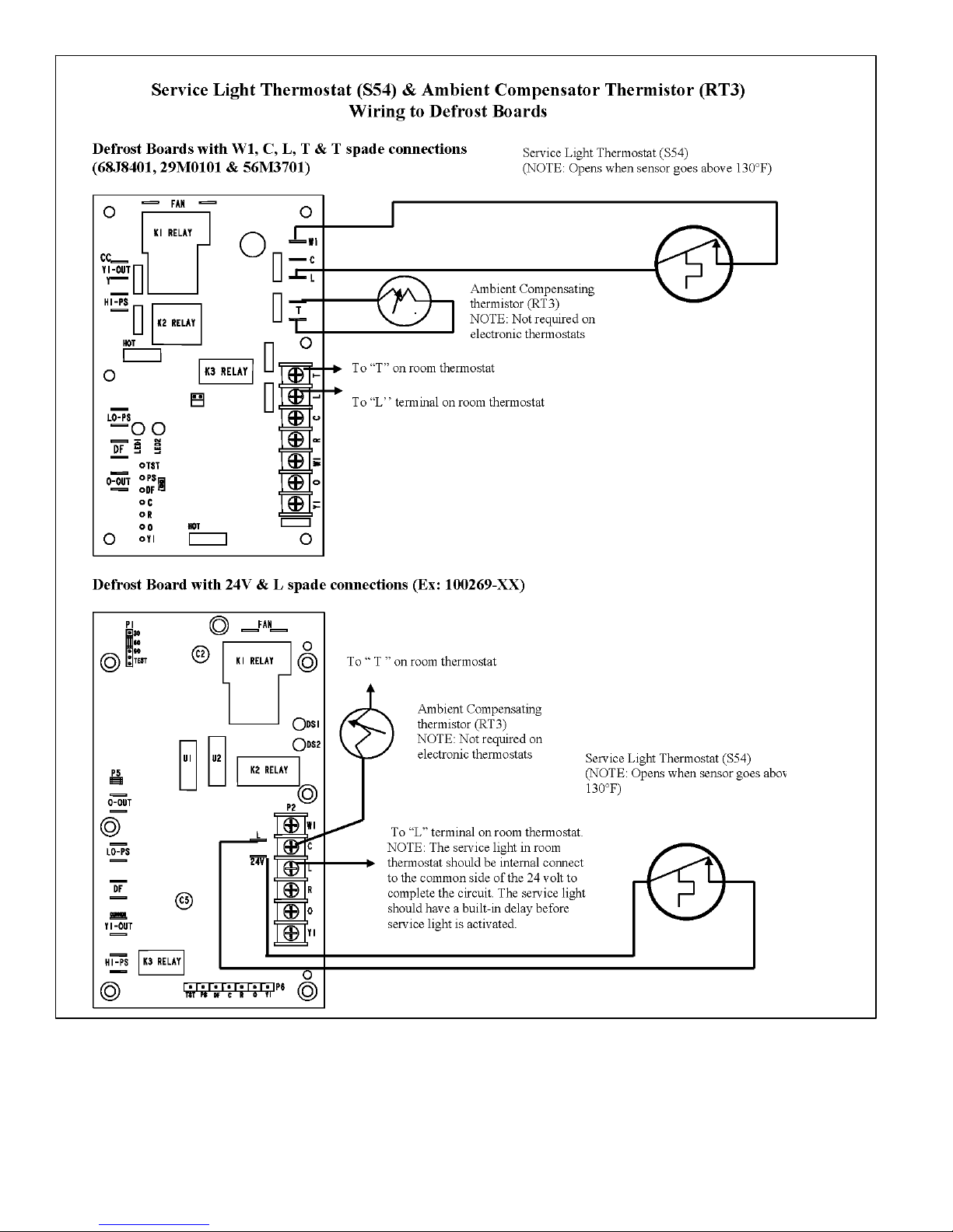
Service Light Connection
The switch is electrically connected to the service light in
the indoor 24 volt mercury style room thermostat. The
service light, when lit, indicates the compressor is not
running. The service light is powered from W1 terminal of
the indoor thermostat. The service light thermostat will
close and light when the discharge line falls below 110 +/-
5°F, indicating a problem in the system. The service light
thermostat opens and the service light goes off when the
discharge line temperature falls to 130 +/- 5°F indicating
the compressor is running. On late model units, the service
light connections are made on terminals on the defrost
control.
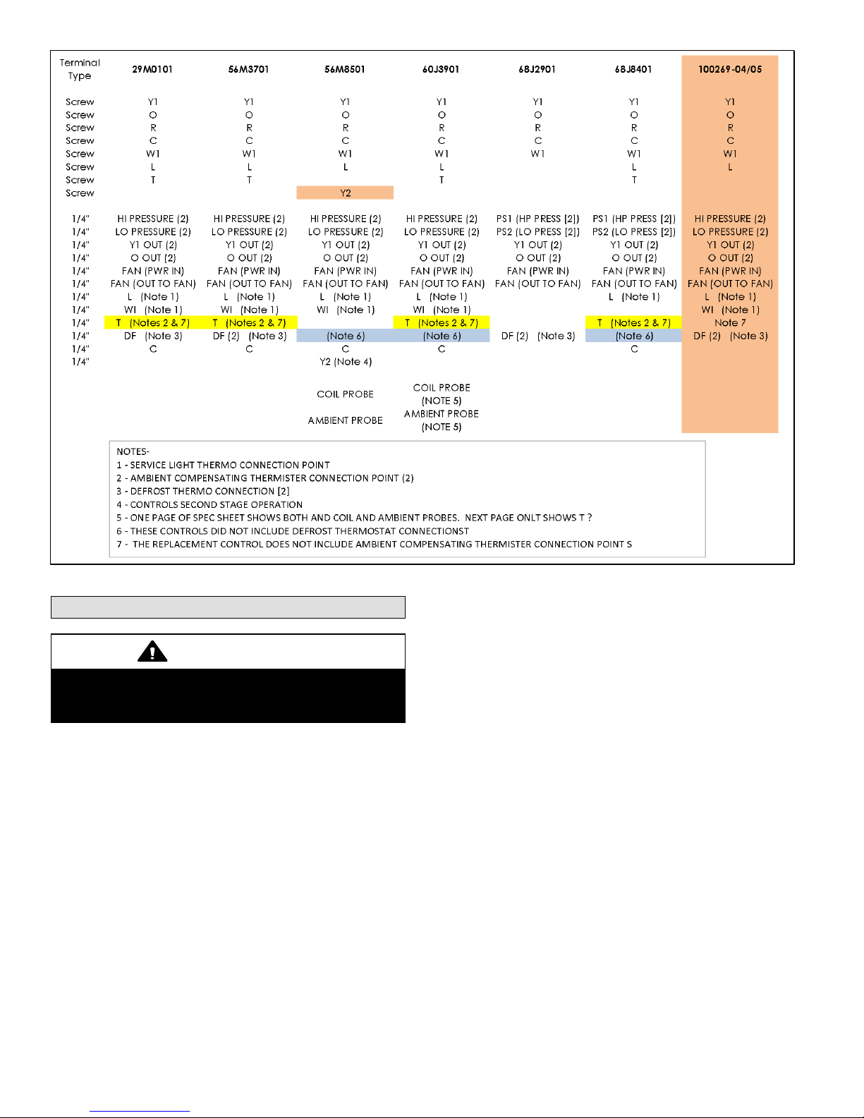
Ambient Compensating Thermistor
NOTE - The ambient compensator thermistor is not
required with 24 volt electronic thermostats.
Units built PRIOR to March 2002 have an ambient
compensating thermistor mounted on the outdoor fan
wiring harness. The thermistor is an NTC (negative
temperature coefficient – increase in temperature equals
decrease in resistance). The device is connected in series
with the heat anticipation resistor in the 24 volt mercury
style room thermostats. The thermistor varies the room
thermostat heat anticipator current according to outdoor
ambient temperature to prevent abnormal thermostat
droop. As outdoor temperature increases, the resistance
across the thermistor drops. As the resistance across the
thermistor drops, the current through the heat anticipator
resistor increases. Therefore, heat anticipation increases
as outdoor temperature decreases. (Resistance at 77ºF =
260 ohms +/- 5%; at 100ºF = 150 ohms; at 32ºF = 861
ohms). On late model units, the ambient thermistor
connections are made at terminals on the defrost control.

Page 4
Figure 2. Typical Unit Wiring Diagrams - Defrost Control with C, L and Y1 Terminals)

Page 5
Figure 3. Typical Unit Wiring Diagrams - Defrost Controls with W1, C, L and T, T terminals)
Figure 4. Earlier Model Defrost Control Terminal Designations for Service Light and Ambient Thermistor
Connections

Page 6
Figure 5. Wiring Ambient Compensator (RT3) and Service Light and Service Light Thermostat (S54) to New
Defrost Control

Page 7
Figure 6. Wiring Ambient Compensator (RT3) and Service Light and Service Light Thermostat (S54) to New
Defrost Control

Page 8
Figure 7. Connector Descriptions
Installation
CAUTION
Label all wires prior to disconnection when servicing con
trols. Wiring errors can cause improper and dangerous
operation. Verify proper operation after servicing.
1. Disconnect all electrical power from the unit.
2. Locate existing defrost control
3. Mark and disconnect wires from existing defrost
control. Remove existing defrost control .
4. Position replacement defrost control properly over
mounting holes in unit and snap stand-offs into place.
5. Reconnect labeled wires to the proper terminals on the
replacement defrost control. Refer to figure 1 for
pressure switch wiring and terminal identification.
6. Remove the factory-installed jumper(s) to install the
existing high pressure and low pressure (or loss of
charge) switch(es).
7. Affix provided sticker to inside of control panel.
8. Restore electrical power to the unit and monitor unit
function through a defrost test cycle.
Table of contents
Other Lennox Control Unit manuals

Lennox
Lennox Carel pGD1 User manual

Lennox
Lennox iHarmony 10C16 Assembly instructions

Lennox
Lennox V8MSBB01 User manual

Lennox
Lennox CLIMATIC 40 User manual

Lennox
Lennox 13J76 User manual

Lennox
Lennox CLIMATIC 40 User manual

Lennox
Lennox CLIMATIC II User manual

Lennox
Lennox EIM Assembly instructions

Lennox
Lennox Zoning System LZP-4 User manual

Lennox
Lennox Harmony III User manual
Popular Control Unit manuals by other brands

HF
HF HF-BL200A user manual

Telcoma Automations
Telcoma Automations T10 FM400 Operation and Programming Instructions

TREND
TREND 3RM/24VAC Installation Instructions-Mounting

Grundfos
Grundfos CIM 1 Series Installation and operating instructions

BASF
BASF EXACTUS IFX-21 user guide

Rasmussen
Rasmussen SPK3E owner's manual