Leroy-Somer GEARLESS Z2 Instruction Manual

This manual is to be given to
the end user
GEARLESS Z2 - Z3
A.C. drive
for elevators
Installation and maintenance
3862 en - 07.2004 / a

2
INSTALLATION AND MAINTENANCE
GEARLESS Z2 - Z3
A.C. Drive for elevators
LEROY-SOMER
3862 en - 07.2004 / a
To ensure that the LEROY-SOMER motor you have just
purchased is entirely satisfactory, it is essential to adhere to
the following instructions.
IMPORTANT: Contact with energised or rotating
parts may cause injury. Do not touch the housing
of a motor that is in operation, as it can reach high
temperatures.
REMINDER: Moving parts are painted yellow, except for
the pulley grooves and the brake disk. Installation,
servicing and maintenance must only be carried out by
qualified personnel.
Failure to follow the instructions in this document, or to
apply them correctly, releases the manufacturer from
liability.
The product is covered by the warranty during the
guarantee period as long as any partial or total
dismantling has only been performed with the assistance
of LEROY-SOMER (or its approval).
CAUTION: Check that the elevator car has been
immobilised before performing any work on the
motor or the brakes.
The magnetic field on the rotor may affect pacemakers.
The motor rotor contains a powerful magnetic field. This field
may affect digital devices such as watches, mobile phones
etc.
Assembly or maintenance of the rotor must not be carried out
by people with pacemakers or any other implanted medical
electronic device.
1 - RECEIPT
Checks:
- as soon as you receive the machine, check that the nameplate on the machine conforms to your order.
- inspect the machine as soon as it is received. If there is any damage that has been caused by transportation, contact the carrier
in the usual way.
AC GEARLESS
MOTOR
BRAKE
Type :
Nom voltage :
Pick up voltage : Current :
16015 ANGOULEME Cedex FRANCE
MADE IN FRANCE
Holding voltage : Current :
A
A
VDC
VDC
Frequency :
Speed : Rpm
Hz
V Current :
Duty cycle :
Elec insulation : H
kW
A Phases :
Nom power :
Protection :
3
Z3
Max sheave load :
Serial N° : 000000 001
Weight :kg kg
Model
Maximum
permissible load
on the pulley
Motor
rated voltage
Motor
rated speed
Pick-up voltage
Holding voltage Holding current
Inrush current
Motor rated power
Motor rated current
Weight of the Gearless
TUV CUS
166631
2103003/A

3
INSTALLATION AND MAINTENANCE
GEARLESS Z2 - Z3
A.C. Drive for elevators
LEROY-SOMER
3862 en - 07.2004 / a
2 - STORAGE
2.1 - Storage location
This location must be dry and protected from harsh weather
conditions, cold (temperature above -15°C), frequent
temperature variations (to prevent the risk of condensation),
and free from vibration, dust and corrosive gases.
If there is any vibration in the storage area, it is advisable to
rotate the driving pulley at least twice a month (the brakes are
released by the manual release system).
In certain transport conditions the grooves of the driving
pulley are protected by a special varnish. This varnish must
not be removed during storage.
2.2 - Prolonged storage (> 3 months)
Place the machine in a sealed waterproof enclosure with a
dehydrating sachet inside corresponding to the volume to be
protected and the degree of humidity of the location.
3 - ENVIRONMENT
The rated characteristics are given for operation in a standard
environment (see IEC 600034-5):
- altitude less than 1000 m,
- maximum humidity: 95%,
- temperature between 0 and 40°C.
Derating may be provided if special conditions are indicated
at the time the equipment is ordered.

4
INSTALLATION AND MAINTENANCE
GEARLESS Z2 - Z3
A.C. Drive for elevators
LEROY-SOMER
3862 en - 07.2004 / a
4 - COMMISSIONING
BEFORE INSTALLATION
If the equipment has been stored for several months, it is
essential to check the following:
- the cleanliness of the interior and that there is no
condensation
- correct insulation between the phases and the earth terminal
on the motor (minimum 100M
Ω
at 500 V D.C. for 60 seconds)
after having disconnected all the electronic circuits if
necessary.
WARNING:
do not apply the megohmmeter to the terminals
of the thermal sensors as this may damage them.
If the required value is not reached, dry using internal or
external heating.
Drying using external heating
- place the motor in an oven at 70°C for at least 24 hours until
the correct insulation is achieved. (100M
Ω
)
- Take care to increase the temperature gradually to clear the
condensation.
- After drying, during the cooling phase, check the insulation
value regularly, as it will initially tend to fall then rise.
Drying using internal heating
- Test to be carried out with the brakes released.
- Connect motor windings V and W in parallel in relation to U.
(see drawing below)
- Read off the resistance between U and V//W.
- Apply a
low voltage
D.C. current to them (to obtain 10% of
the rated current calculated using the resistances of the
winding), increase the voltage until 50% of the rated current
is reached.
- Maintain the power for 4 hours. The temperature of the
motor should increase slightly.
CAUTION: The pulley will move slightly on power-
up (angular setting of the rotor in relation to the
stator).
4.1 - INSTALLATION
The installation must comply with the characteristics of the
motor indicated on the nameplate (see section 1).
It must include electrical safety devices.
Check that the handling equipment (slings, etc.) are suitable
for the weight of the machine.
Use the attachment points provided on the machine.
Check that the cables are correctly positioned so that they are
not damaged.
Provide the necessary mechanical protection devices to
prevent people working on the machine becoming caught or
trapped by the pulley and/or the cables.
The motors must be installed in such a way that the cooling
air (not too damp, dust-free, and containing no vapour or
corrosive gas) circulates freely.
4.1.1 - Cleaning
- Release the brake using the manual release system.
- Remove the protective varnish from the pulley grooves.
CAUTION: Do not use abrasive equipment. Use
only a cloth soaked in alcohol. Care must be taken
not to get any alcohol or grease on the brake disk.
WARNING:
use the alcohol in a well ventilated area.
Z2-Z3 Fabricated steel shield
Motor connection for drying the winding
Phase connection
Power supply (-) U
Power supply (+) V + W (serial)
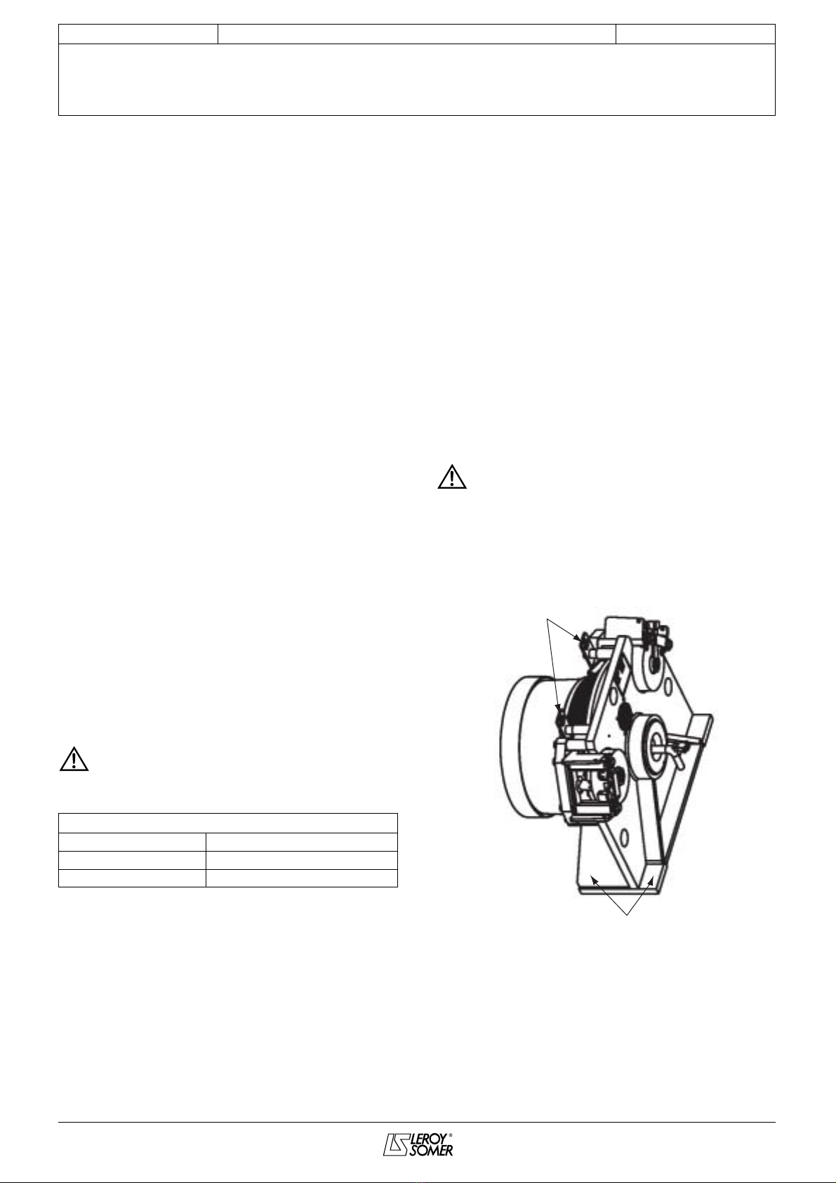
Anchoring points
for lifting
Fixing screws

5
INSTALLATION AND MAINTENANCE
GEARLESS Z2 - Z3
A.C. Drive for elevators
LEROY-SOMER
3862 en - 07.2004 / a
Z2-Z3 Cast iron shield
4.1.2 - Mechanical installation
- The GEARLESS machine must be installed on a chassis
that is not subject to vibrations and must be secured. Cast
iron shield = 4 M14 bolts and washers, fabricated steel shield
= 4 M12 bolts and washers. The bolts must only be tightened
when the cables, car, counterweights and driving pulley are
perfectly aligned. Before installing the cables, check that the
driving pulley can be rotated freely by hand when the brakes
are released.
Z2-Z3 Protection
- Check that the cables are of the correct type for the pulley.
- When the cables have been installed, adjust the distance
between the cables and the protection then tighten the
guards.
CAUTION: There is a high risk of jamming between
the cables and the pulley.
4.2 - Wiring
- See the connection diagrams below.
Fig. 1
Motor cable length 2 m
Length of thermal sensor cable 2 m
Fig. 2 - Motor connection
Brake wiring
- Continuous supply (see name plate).
- Connect the motor using cables of the correct cross-section
(the cables and tags must be sized according to the current:
see the table below). Particular care must be taken to tighten
the nuts on the terminals. (Incorrect tightening may lead to the
connections being damaged by overheating: see the diagram
below.)
This table is given for information only, and must under no
circumstances be used in place of the current standards.
The recommended cross-sections are given for a single-
wire cable, with a maximum length of 10 m. Above this,
line drops due to the length must be taken into account.
Points d'ancrage
pour levage
Anchoring points
Fixing screws
Points d'ancrage
pour levage
Groove
protection guard
Phase output
U Phase 1
V Phase 2
W Phase 3
Ground/Earth Green/Yellow
Phase output
1 PTC
2 PTC
Type Colour Marking
Brake power supply Yellow - BM
Green + BM
Microswitch White CM1
Brown CM2
Rated current (A) per
9.5 12 16 25 34 40 46
Min cable section (mm
2
)
1.5 1.5 2.5 4 6 10 10
AWG
15 15 13 11 9 7 0
approx: 2 m
U
U1
C1
C2
U2
W
W1 V1
V
V2W2

6
INSTALLATION AND MAINTENANCE
GEARLESS Z2 - Z3
A.C. Drive for elevators
LEROY-SOMER
3862 en - 07.2004 / a
CAUTION: It is the responsibility of the user to
connect the motor in accordance with the current
legislation and regulations in the country of use. This is
particularly important as regards the size of the cables,
the type and size of fuses, the earth or ground
connection, powering down, acknowledging faults,
insulation and protection against overcurrents.
- Connect the power cables to terminals U1, V1 and W1, in
accordance with IEC 600034-1 (see section 4.2 - fig. 1).
- Connect the thermal probe to the drive.
- Connect the motor ground to earth (see section 4.2 - fig. 1).
- Connect the brakes and the microswitches.
- Connect the encoder.
4.3 - Start-up
Check that the electric controls are correctly earthed before
carrying out the first operation.
Start up the machine and check the following points:
- All the fixings and electrical connections must be correctly
tightened.
After starting up, check:
- noise
- vibration
- operation of the buttons/switches
- also check the current and voltage on the machine while it
is operating with the rated load.
- Encoder wiring (refer to the data sheet).
5 - MAINTENANCE/SERVICING
5.1 - After one month’s operation
- Check that the screws and electrical connections are
correctly tightened.
- Check the vibration. Check that there is no abnormal noise.
- Remove any traces of grease (if there are any) from the
brake disks.
- Check that the noise level of the brakes is less than 60 dBA.
If the observed noise level is above this value, inform LEROY-
SOMER.
- If the brake wear needs to be checked: measure the brake
air gap (it must be between 0.2 mm and 0.4 mm) using the
checking method described in section 6.
Note: this measurement will be used as a reference.
5.2 - Every year
- Check that the noise level of the brakes is less than 60 dBA.
If it is not, adjust the brakes, as described in section 6.
- If the wear needs to be checked, ensure that the air gap is
less than 0.5 mm. If it is not: check that the motor is not
starting with the brakes engaged, otherwise contact LEROY-
SOMER.
IncorrectCorrect
Te r minals
Te r minals

7
INSTALLATION AND MAINTENANCE
GEARLESS Z2 - Z3
A.C. Drive for elevators
LEROY-SOMER
3862 en - 07.2004 / a
6 - BRAKE ADJUSTMENT
PROCEDURE
6.1 - Air gap adjustment tolerance
6.2 - Checking and adjusting the air gap
(brakes de-energised)
6.2.1 - Check the brake air gap
1 - Measure the air gap using a set of adjustment shims at the
points indicated (between the armature and the brake
housing).
2 - The brake is correctly adjusted if the air gap is between
0.25 and 0.3 mm (factory setting).
6.2.2 - Adjusting the brake air gap
1 - Unlock and loosen the lock nuts on the brake adjustment
screws.
2 - Insert two 0.25 mm adjustment shims in the air gap at the
points indicated (in order to avoid the antivibration mounts
and the springs).
3 - Re-tighten the adjustment screws alternately, so that the
shims slide in easily.
4 - Tightly re-lock the lock nuts on the adjustment screws
while firmly holding the adjustment screws.
5 - After adjusting the air gap, the adjustment must be
checked (section 6.3) and if necessary, the microswitches
adjusted (section 6.4).
6.3 - Checking the adjustment of the air
gap (with the brakes energised)
1 - Energise the brakes.
2 - Check the level of noise of each brake (no rattling) and
ensure that the pulley rotates freely with the brakes released.
If there is too much noise, re-adjust the brake using 0.20 mm
shims.
3 - After this operation, it is essential to check the adjustment
of the microswitches.
6.4 - Checking and adjusting the
microswitches
- Each brake calliper has a microswitch.
- The microswitches are closed when the brake is engaged
(active).
- The microswitches are wired in series (if there are several
brakes).
1 - Check the microswitches using an ohmmeter.
2 - Check each microswitch in succession after short-
circuiting the others. The check is carried out by activating the
brake several times (releasing/engaging) at a minimum of
3 equidistant points during one complete rotation of the brake
disk.
3 - The adjustment must be carried out with the brake
energised (released).
- using the M6 grub screw (diagram below) and the lock nut,
which is lightly tightened, adjust the screw, then retighten until
it is firmly fastened. Then tighten one further half turn and lock
the lock nut.
4 - Check sections 1 and 2
5 - Perform the same operation on the other microswitches
Prohibited
0.1 mm 0.2 mm 0.3 mm 0.4 mm 0.5 mm
Prohibited
Modification of the air gap by adjustment
Set of shims for
adjusting the air gap
Brake lining
pads
Air gap
adjustment
screw
Brake
disk
Lock
nut
Travel
measurement,
detection screw
Nut
Air gap Screw Microswitch

8
INSTALLATION AND MAINTENANCE
GEARLESS Z2 - Z3
A.C. Drive for elevators
LEROY-SOMER
3862 en - 07.2004 / a
7 - ORDERING SPARE PARTS
To ensure optimum after-sales service, the following information must be provided with each spare parts order:
- type and serial number of the motor
and for each spare part:
- Name and (or) reference number of the part
- quantity ordered.
For instant identification, please give the reference of the document used for the order (drawing number or manual). The type and
serial number can be found on the nameplate of the motor.
Part names:
1 - Stator (not visible) 5 - Pulley 9 - Lifting rings
2 - Rotor 6 - Cable outlet 10 - Encoder (not visible)
3 - Pulley shaft 7 - Brake disk 11 - Brake switch
4 - Brake shield 8 - Brakes 12 - Motor cover
5
7
9
2
10
12
8
4
6
3
1
11

9
INSTALLATION AND MAINTENANCE
GEARLESS Z2 - Z3
A.C. Drive for elevators
LEROY-SOMER
3862 en - 07.2004 / a

10
INSTALLATION AND MAINTENANCE
GEARLESS Z2 - Z3
A.C. Drive for elevators
LEROY-SOMER
3862 en - 07.2004 / a


LEROY-SOMER 16015 ANGOULÊME CEDEX - FRANCE
RCS ANGOULÊME N° B 671 820 223
S.A. au capital de 62 779 000
€
www.leroy-somer.com
This manual suits for next models
1
Table of contents
Other Leroy-Somer DC Drive manuals
Popular DC Drive manuals by other brands

Danfoss
Danfoss VLT AutomationDrive FC 300 operating instructions

Bosch
Bosch Active Line Plus BDU 350 Original operating instructions

Moog
Moog ISA1 Series instruction manual

PR electronics
PR electronics Hart 5107B manual

REDEX ANDANTEX
REDEX ANDANTEX Z Series Setup and maintenance instructions

Festo
Festo EMCA-EC-67 CO Series Description