Leuze electronic MSI 420.TMC-03 User manual

MSI 420.TMC-03
TMC 66 Legacy
SAFE IMPLEMENTATION AND OPERATION
Original operating instructions
2019/10/08 - 50143065
We reserve the right to
make technical changes

Leuze electronic MSI 420.TMC-03
Leuze electronic GmbH + Co. KG
In der Braike 1
D-73277 Owen / Germany
Phone: +49 7021 573-0
Fax: +49 7021 573-199
http://www.leuze.com
Exemption of liability
Leuze electronic GmbH + Co. KG is not liable in the following cases:
• Safety relay is not used as intended.
• Safety notices are not adhered to.
• Reasonably foreseeable misuse is not taken into account.
• Mounting and electrical connection are not properly performed.
• Proper function is not tested (see Table 4.3 on page 13).
• Changes (e.g., constructional) are made to the safety relay.
• Changes are made to the software configuration.
• The supplied memory card is changed without corresponding instruction from Leuze electronic.

Leuze electronic MSI 420.TMC-03 1
1 About this document. . . . . . . . . . . . . . . . . . . . . . . . . . . . . . . . . . . . . . . . . . . . . . . 2
1.1 Useful documents . . . . . . . . . . . . . . . . . . . . . . . . . . . . . . . . . . . . . . . . . . . . . . . . . . . . . . . . 2
1.2 Delivery contents and part number . . . . . . . . . . . . . . . . . . . . . . . . . . . . . . . . . . . . . . . . . . . 2
2 System overview . . . . . . . . . . . . . . . . . . . . . . . . . . . . . . . . . . . . . . . . . . . . . . . . . 3
2.1 Features. . . . . . . . . . . . . . . . . . . . . . . . . . . . . . . . . . . . . . . . . . . . . . . . . . . . . . . . . . . . . . . . 3
2.2 System limits . . . . . . . . . . . . . . . . . . . . . . . . . . . . . . . . . . . . . . . . . . . . . . . . . . . . . . . . . . . . 4
2.3 Muting sensors . . . . . . . . . . . . . . . . . . . . . . . . . . . . . . . . . . . . . . . . . . . . . . . . . . . . . . . . . . 4
2.4 Protective sensors . . . . . . . . . . . . . . . . . . . . . . . . . . . . . . . . . . . . . . . . . . . . . . . . . . . . . . . . 4
2.5 System response time . . . . . . . . . . . . . . . . . . . . . . . . . . . . . . . . . . . . . . . . . . . . . . . . . . . . . 4
3 Description of functions . . . . . . . . . . . . . . . . . . . . . . . . . . . . . . . . . . . . . . . . . . . . 5
3.1 Arrangement of the muting sensors. . . . . . . . . . . . . . . . . . . . . . . . . . . . . . . . . . . . . . . . . . . 5
3.2 Signals . . . . . . . . . . . . . . . . . . . . . . . . . . . . . . . . . . . . . . . . . . . . . . . . . . . . . . . . . . . . . . . . . 5
3.3 Muting phases . . . . . . . . . . . . . . . . . . . . . . . . . . . . . . . . . . . . . . . . . . . . . . . . . . . . . . . . . . . 6
3.4 Override - Starting system with occupied protective sensor . . . . . . . . . . . . . . . . . . . . . . . . 9
3.5 Reactivation of muting . . . . . . . . . . . . . . . . . . . . . . . . . . . . . . . . . . . . . . . . . . . . . . . . . . . . . 9
4 Electrical connection and commissioning. . . . . . . . . . . . . . . . . . . . . . . . . . . . . . 10
5 Diagnostics messages . . . . . . . . . . . . . . . . . . . . . . . . . . . . . . . . . . . . . . . . . . . . 15
6 Maintenance. . . . . . . . . . . . . . . . . . . . . . . . . . . . . . . . . . . . . . . . . . . . . . . . . . . . 16
6.1 Regular checks on protective device by competent persons. . . . . . . . . . . . . . . . . . . . . . . 16
7 Service and support . . . . . . . . . . . . . . . . . . . . . . . . . . . . . . . . . . . . . . . . . . . . . . 16
8 EU/EC Declaration of Conformity. . . . . . . . . . . . . . . . . . . . . . . . . . . . . . . . . . . . 17

Leuze electronic MSI 420.TMC-03 2
1 About this document
This document is a translation of the original operating instructions for the product MSI 420.TMC-03. It
describes handling of the discontinued TMC 66 (Leuze article no. 50082121) and how to replace the TMC
66 for the substitute MSI 420.TMC-03. The latter is also referred to below as the
TMC 66 Legacy
solution.
1.1 Useful documents
This document contains only the most important facts and information relevant to this specific application
(
TMC 66 Legacy
). For further details or specific data sheet information, please refer to the following docu-
ments:
MSI 400 hardware manual
The German and English version of the manual can be downloaded at our website www.leuze.com by
entering the article number (50142625). Please also refer to the manual for the used protective sensor.
1.2 Delivery contents and part number
Table 1.1: Delivery contents and part numbers
Part no. Designation Description
50142625 MSI 420.TMC-03
TMC 66 Legacy
complete solution
Scope of delivery
MSI 420-03 Configurable compact safety control with
spring-cage terminals including operating
instructions for the MSI 400 system.
MSI-SD-CARD Preconfigured memory card, inserted in the
MSI 420-03.
MSI-SD-COVER Cover to protect the memory card, installed.
User's guide
MSI 420.TMC-03
Complete user's guide (this document) can
be downloaded at www.leuze.com by enter-
ing the article number (50142625).

Leuze electronic MSI 420.TMC-03 3
2 System overview
The
TMC 66 Legacy
system is based on the MSI 400 safe compact control from Leuze electronic. The
system is a substitute for the TMC 66 (Leuze electronic article no. 50082121) and is used only as a
replacement solution.
The solution essentially consists of a hardware component and software functionality specifically config-
ured for this application. The latter emulates the original behavior of the TMC 66, thus enabling simple
replacement of the old device.
The software functionality is already stored on the supplied memory card on delivery. The program has
already been verified so that the program sequence is executed automatically as soon as the
MSI 420.TMC-03 is connected to the supply voltage and has completed a self test.
Owing to the preconfigured memory card, it is not necessary to make any changes to the logic program
during commissioning.
If the memory card needs to be changed, this must always be done by a Leuze electronic service techni-
cian.
If Leuze electronic explicitly instructs you to change the memory card (e.g. in the event of an update), this
can be done by a competent person, taking the relevant work instructions into consideration.
2.1 Features
Four different operating modes are available:
• Operating mode 1: Start/restart interlock active; contactor monitoring inactive
• Operating mode 2: Start/restart interlock inactive; contactor monitoring inactive
• Operating mode 3: Start/restart interlock active; contactor monitoring active
• Operating mode 4: Start/restart interlock inactive; contactor monitoring active
The respective operating mode is selected by means of a wire bridge, see table 4.2 "Selection of operating
mode".
Three signal outputs for indicating the status (for details, see chapter 5 "Diagnostics messages")
•Error
• Safety on
• Error indication
NOTE
During development of the replacement solution, great importance was placed on 1:1 exchangeability
(wiring and functionality) with the TMC 66. Nevertheless, some aspects with respect to the handling and
system behavior of the replacement solution differ from the TMC 66. The main differences are described
at the appropriate point in this document.
NOTE
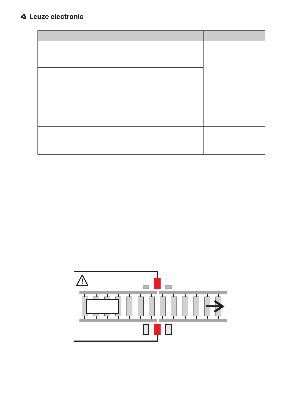
When designing new systems with muting, we recommend using our MLC SPG (Smart Process Gating).
This system will enable you to completely dispense with muting sensors. This will not only save space,
but will also reduce the amount of mounting and installation work required. We would be glad to advise
you in a personal consultation.
NOTE
The supplied software functionality was developed and tested in accordance with the directives appli-
cable for so-called SRASW (Safety-Related Application Software), as defined in ISO 13849-1.
ATTENTION
Before connecting the MSI 420.TMC-03 to the supply voltage, make sure that the device has been
connected in accordance with the supplied wiring plan.
Commissioning may only be performed by a competent person and following the steps given in the
section Electrical connection and commissioning (see chapter 4 "Electrical connection and commis-
sioning").

Leuze electronic MSI 420.TMC-03 4
2.2 System limits
The maximum attainable performance level of the overall system is limited to PL c (ISO 13849-1).
Differences to TMC 66:
• No monitoring of the muting lamp because this function is no longer stipulated in the relevant stan-
dards. This means that a defective muting lamp is not detected by the MSI 420.TMC-03.
• No 7-segment display. Instead, the error display is implemented using three diagnostics outputs (see
chapter 5 "Diagnostics messages").
• The safety outputs of the MSI 420.TMC-03 units are semiconductor outputs with a switching power
of up to 4A. If potential-free outputs are required, a relay must additionally be used.
• No DIP switches for setting the different operating modes. The operating mode is selected via a bit
pattern at the inputs of the MSI 420.TMC-03 (see chapter 4 "Electrical connection and commission-
ing")
2.3 Muting sensors
Throughbeam or retro-reflective photoelectric sensors with activation input (PNP HIGH active) can be
used as muting senders for the MSI 420.TMC-03.
2.4 Protective sensors
The used protective sensor must achieve at least the following characteristic safety values. Type 2 (acc.
to 61496-2), PL c and category 2 (acc. to ISO 13849-1). Furthermore, the information in the manual of the
used protective sensors must also be observed.
2.5 System response time
The response time is the time taken for the safety function to be called.
Example: The time from entry into the protective sensor until shutdown of the machine.
When the safety distance as defined in ISO 13855 and required for the respective application is calculated,
a total reaction time of 35.6 ms must be factored in for the response time of the MSI 420.TMC-03 (MSI 400
hardware + software functionality).
The response times of the sensor and actuator must be considered separately and must be taken from the
respective manufacturer's manual.

Leuze electronic MSI 420.TMC-03 5
3 Description of functions
By means of muting, the protective function of the safety sensor can be temporarily and properly
suppressed, e.g. if objects are to be transported out of the danger zone through the protective field. The
OSSDs of the MSI 420.TMC-03 remain in the ON state in spite of interruption of the protective sensor.
3.1 Arrangement of the muting sensors
Muting sensors detect the transport material and supply the signals necessary for muting. Standard
IEC 62046 provides basic information on arranging the muting sensors. This information must be observed
when mounting the muting sensors.
Operation of the MSI 420.TMC-03 is described below based on the various phases of the muting process.
3.2 Signals
Table 3.1: Signals
WARNING
Serious accidents caused by incorrect set-up!
If the distance between transmitter and receiver is larger than the width of the object so that gaps of more
than 180 mm are created, suitable measures, e.g. through additional guarding, must be taken to stop the
dangerous movement before persons enter the area.
Make sure that no persons can reach the danger zone alongside the transport material during muting.
Make sure that muting is only temporarily activated and only as long as the access to the danger zone
is blocked by the transport material.
NOTE
If accessible distances exist between the transport material and the safety sensor, PS mats or wicket
gates monitored with safety switches have been tried, tested and proven as additional safeguards. Such
measures prevent injuries caused, for example, by crushing in the access area.
WARNING
Unintentionally triggered muting may result in serious injury!
Mount the muting sensors in such a way that muting cannot be unintentionally triggered by a person,
e.g. by simultaneously activating the muting sensors with a foot.
Mount the muting indicator so that it is always visible from all sides.
WARNING
Risk of death through inadequate protection of the muting sensors!
Protection against unintended initiation of the (permanent) bridging through mechanical damage and/
or misalignment of muting sensors (acc. to IEC 62046).
Signals at MSI 400 Source Description
Control 1 Input E.g. standard PLC
(source A)
Preparations for muting
Control 2 Input E.g. motor contactor of
conveyor belt (source B)
Preparations for muting

Leuze electronic MSI 420.TMC-03 6
3.3 Muting phases
Phase 1 - Preparing muting
First, the two control signal inputs on the MSI 400 must be activated, i.e. a HIGH signal must be present
at each input. When doing so, it is essential to ensure that the control signals originate from different signal
sources. Typically, the Control 1 signal is generated by the PLC whereas the Control 2 signal comes from
the conveyor belt (e.g. motor contactor).
The sequence in which the control signals are applied is irrelevant for operation of the MSI 400. The time
period between application of Control 1 and Control 2 can be between 0 ms and any length of time. The
control signals must remain active (HIGH level) throughout the entire muting process.
To test the muting sensors, the MSI 400 outputs a test pulse at the Start 1 OUT / Start 2 OUT outputs.
Each time an edge change is requested, a maximum reaction time (tR) of 240 ms is available for the
sensors. This means that at the Start 1 IN / Start 2 IN inputs the MSI 400 expects them to follow the
predefined signal change within the predefined time. The muting function is ready as soon as testing of
Start 1 and Start 2 has been successfully completed.
If tR is exceeded, muting is not initiated and an error message is output (see chapter 5 "Diagnostics
messages").
Start 1 Start 1 IN, input Muting sensor 1, receiver A test cycle initiated by the
MSI 400 checks whether
an edge change pre-
defined at "Start 1 OUT/
Start 2 OUT" is registered
by the muting sensor and
returned to the MSI 400 via
"Start 1 IN/Start 2 IN".
Start 1 OUT, output Muting sensor 1, transmit-
ter
Start 2 Start 2 IN, input Muting sensor 2, receiver
Start 2 OUT, output Muting sensor 2, transmit-
ter
SLS receiver Input Protective sensor Receiver of the protective
sensor
SLS transmitter Test output Protective sensor Transmitter of the protec-
tive sensor
Start/activation input Input External sensor or PLC Depending on the operat-
ing mode, this input func-
tions as the start input or
activation input
Signals at MSI 400 Source Description
Figure 3.1: Phase 1 - Muting preparation is activated by applying the control signals. The pallet is still
completely inside the danger zone.
Danger zone Protective sensor
Start 1 Start 2

Leuze electronic MSI 420.TMC-03 7
Phase 2 - Activating muting
As soon as the first muting sensor is interrupted, i.e. the Start 1 signal is LOW, the protective sensor is
bridged - muting is active.
Phase 3 - Interruption of the protective sensor
While the transport material occupies the first muting sensor, the protective sensor is additionally inter-
rupted. As the system is in the muting state, the safety outputs are not deactivated.
Phase 4 - Interruption of Start 2
At the earliest 5 ms after Start 1 has been interrupted, Start 2 is also allowed to be interrupted by the trans-
port material. During this phase, the two muting sensors (i.e. both start signals) as well as the protective
sensor must be occupied (LOW level).
A maximum time between occupancy of Start 1 and Start 2 is not monitored by the device.
Figure 3.2: Phase 2 - Muting is activated by the interruption of Start 1.
Figure 3.3: Phase 3 - Protective sensor is interrupted.
Figure 3.4: Phase 4 - Continuation of the muting process with occupancy of Start 2 by the pallet.
Danger zone Protective sensor
Start 1 Start 2
Danger zone Protective sensor
Start 1 Start 2
Danger zone Protective sensor
Start 1 Start 2

Leuze electronic MSI 420.TMC-03 8
Phase 5 - Start 1 becomes free
The transport material releases muting sensor 1 (Start 1) again while the protective sensor is still inter-
rupted.
Phase 6 - Protective sensor becomes free
Muting still remains active after the transport material releases the protective sensor again.
Important: To ensure that the direction of the pallet (from the danger zone i n t o t h e s a f e z o n e ) i s
detected correctly, Start 2 must be occupied before Start 1 becomes free again. If an error is de-
tected during direction monitoring, the muting process is terminated and an error message is ac-
tivated (see chapter 5 "Diagnostics messages")
Important: If Start 1 and Start 2 come from the PLC: The Start 1 signal may only be reactivated
(direction detection) after the transport material has been completely transported out of the dan-
ger zone and Start 2 is no longer interrupted.
NOTE
Unnecessarily long muting should be avoided in all cases.
Figure 3.5: Phase 5 - Muting continues even after Start 1 has been released.
Figure 3.6: Phase 6 - Protective sensor becomes free again.
Danger zone Protective sensor
Start 1 Start 2
Danger zone Protective sensor
Start 1 Start 2

Leuze electronic MSI 420.TMC-03 9
Phase 7 - End of muting
The muting process is only ended and the protective sensor only resumes normal operation again after
the second muting sensor (Start 2) is no longer occupied by the pallet.
The muting process is generally ended as soon as one of the following signal changes occurs:
Control signals switched off
• Deactivation of Control 1 (signal change from HIGH to LOW)
• Deactivation of Control 2 (signal change from HIGH to LOW)
Start 2 switched on
• Activation of Start 2 (signal change from LOW to HIGH)
As soon as the MSI 400 detects one of the listed signal changes, bridging of the protective sensor is
canceled immediately.
3.4 Override - Starting system with occupied protective sensor
The Override function allows transported objects to be removed if they have come to a standstill in the
protective field of the protective device (e.g. photoelectric sensor) due to power failures, the triggering of
an emergency stop, muting errors or other similar circumstances.
If a valid override sequence with a LOW-HIGH-LOW transition (min. 350 ms and max. 3 s; longer or
shorter pulses are ignored) occurs at input I2, the release output becomes HIGH as if the muting conditions
were fulfilled.
3.5 Reactivation of muting
Reactivation of the bridging function is only possible after the system has been reset to the base state.
To do this, the following conditions must be satisfied:
•Control 1 signal set to LOW potential
•Control 2 signal set to LOW potential
•Start 1 IN signal set to HIGH potential
•Start 2 IN signal set to HIGH potential
Muting can then be restarted by activating the two control signals.
Figure 3.7: Phase 7 - End of muting
Danger zone Protective sensor
Start 1 Start 2
WARNING
Unmonitored overrides may result in serious injury!
A person with the necessary competence must observe the procedure exactly.
Make certain that the danger zone can be viewed from the start button and that the entire process can
be observed by a responsible person.
Before and during the override, ensure that there are no people in the danger zone.

Leuze electronic MSI 420.TMC-03 10
4 Electrical connection and commissioning
Before you begin with the installation and commissioning of the
TMC 66 Legacy
, please observe the
following notes:
• Make sure that the system is disconnected from the power supply.
• Make sure that no one is in the danger zone.
• Check the danger zone and take measures to prevent persons from entering (e.g. erect warning
signs, set up cordons or similar).
Step 1: Replace the defective TMC 66 with the MSI 420.TMC-03
The table below shows the wiring for the existing signals.
Table 4.1: Rewiring TMC66 to MSI 420.TMC-03
NOTE
Laying cables!
Lay all connection cables and signal lines within the electrical installation space or permanently in
cable ducts.
Lay the cables and lines so that they are protected against external damages.
For further information: see EN ISO 13849-2, Table D.4.
TMC66 MSI 420.TMC-03 Designation Comment
1T1 SLS activation
2I1 SLS input
3I2 Start/activation input see chapter 3 "Description of func-
tions"
4I3 Contactor monitoring input Only relevant in operating mode 3
and 4
5IQ1 "Error" signal output
6IQ2 "Safety on" signal output
7IQ3 Start 1 active Muting sensor transmitter
8I4 Start 1 edge Muting sensor receiver
9IQ4 Start 2 active Muting sensor transmitter
10 I5 Start 2 edge Muting sensor receiver
11 A1/B1/B2 + 24 V
12 A2 GND
13 I6 Control 1
14 I7 Control 2
15 Q3 Indicator light 1 Muting lamp not monitored by the
MSI 420.TMC-03
16 n.c. Indicator light 2 MSI 420.TMC-03 provides only one
output for the muting lamp
n.c. Q4 "Error indication" signal output see chapter 5 "Diagnostics mes-
sages"
17/18 Q1 Safety output 1 Semiconductor output (PNP)

Leuze electronic MSI 420.TMC-03 11
Step 2: Selection of operating mode
To select the desired operating mode, install the corresponding wire bridges as specified in table 4.2. In
the delivery state, no wire bridges are installed, hence operating mode 1 is configured. The selected oper-
ating mode must be validated by a competent person. If, for example, operating mode 3 has been
19/20 Q2 Safety output 2 Semiconductor output (PNP)
n.c. I10 Selection of operating mode see table 4.2 "Selection of operat-
ing mode"
n.c. I11 Selection of operating mode see table 4.2 "Selection of operat-
ing mode"
n.c. I12 Selection of operating mode see table 4.2 "Selection of operat-
ing mode"
TMC66 MSI 420.TMC-03 Designation Comment
Figure 4.1: Connection example for MSI 420.TMC-03 with start/restart interlock and contactor monitor-
ing (operating mode 3)

Leuze electronic MSI 420.TMC-03 12
selected, it must be checked whether both the start/restart interlock and the contactor monitoring are active
in the application.
Table 4.2: Selection of operating mode
Step 3: Check alignment of muting sensors and protective sensor
Before the supply voltage is applied for the first time, it should be checked whether the muting sensors and
the protective sensor are aligned in accordance with the product-specific operating instructions and not
concealed by other objects.
Step 4: Apply supply voltage
Switch on the supply voltage of the MSI 420.TMC-03 and wait until the control has performed the self test
(approx. 5 seconds). The following indicators now light up on the front of the MSI 400:
PWR/EC LED: green
The voltage supply is between 16.8 V and 30 V.
MS LED: green
The control is started.
CV LED: orange
The project on the control has been verified. The control will start automatically.
If the device is not in this state, table 5.1 „Diagnostics messages“ in this document or the operating instruc-
tions supplied with MSI 420 (chapter 3.2 "Interfaces and display elements") can be used for the purpose
of error diagnosis.
Step 5: Make ready for operation
The start/activation input (I2) functions in two ways in the operating modes with/without start/restart inter-
lock:
• In the operating mode with start/restart interlock, the MSI 420.TMC-03 expects two signal changes
as the switch-on signal (sensor function). A fault in the start button, e.g. caused by welded contacts,
is reliably detected by the MSI 420.TMC-03.
• In the operating mode without start/restart interlock, the input functions as an activation input and
must be supplied with power via the 24 V voltage supply. As soon as a HIGH active signal is present
at I2 and the protective field is free, the safety outputs are closed.
Step 7: Check operation of MSI 420.TMC-03
After successful commissioning, operation of the device can be fully tested. To do this, proceed as follows:
• Interrupt the protective sensor; the safety outputs Q1/Q2 must change their status display. From
green (active) to red (inactive). The downstream contactors are switched off and the dangerous
movement is stopped.
• Align the muting sensors (inputs I4/I5 must be green/active)
• Connect the two control inputs (I6/I7 must be green/active)
• Allow the transport material to pass through the protective sensors as described in chapter 3.3.
MSI 420.TMC-03 Selection
Operating mode 1 Start/restart interlock active, con-
tactor monitoring inactive
I10 (n.c), I11 (n.c), I12 (n.c)
Operating mode 2 Start/restart interlock inactive,
contactor monitoring inactive
I10 ->24V
Operating mode 3 Start/restart interlock active, con-
tactor monitoring active
I11 ->24V
Operating mode 4 Start/restart interlock inactive,
contactor monitoring active
I12 ->24V

Leuze electronic MSI 420.TMC-03 13
The following checklist should also be observed. It will provide assistance when performing the general
check on a safety-relevant system.
Table 4.3: Checklist
Check: Yes No n. a. not
applicable
Does the configured operating mode meet the requirements of the applica-
tion and has it been validated by a competent person?
Is the safety sensor operated acc. to the specific environmental conditions
that are to be maintained?
Are safety sensor, connection cables, connectors, protection caps and
command devices undamaged and without any sign of manipulation?
Does the safety sensor satisfy the required safety level (PL, SIL, category)?
Are the safety-related switching outputs (OSSDs) integrated in the down-
stream machine control acc. to the required safety category?
Are switching elements that are controlled by the safety sensor monitored
according to the required safety level (PL, SIL, category) (e.g., contactors
through EDM)?
Are all points of operation near the safety sensor accessible only through
the protective field of the safety sensor?
Are the necessary additional protective devices in the immediate surround-
ings (e.g., safety guard) properly mounted and secured against tampering?
If it is possible to be present undetected between the safety sensor and
point of operation: is an assigned start/restart interlock functional?
Is the command device for unlocking the start/restart interlock mounted in
such a way that it cannot be reached from within the danger zone and so
that the complete danger zone can be seen from the installation location?
Has the maximum stopping time of the machine been measured and docu-
mented?
Is the required safety distance maintained?
Does interruption with a test object intended for this purpose cause the dan-
gerous movement(s) to stop?
Is the safety sensor effective during the entire dangerous movement(s)?
Is the safety sensor effective in all relevant operating modes of the
machine?
Is start-up of dangerous movements reliably prevented if an active light
beam or the protective field is interrupted with a test object intended for this
purpose?
Was the sensor detection capacity successfully tested?
Were distances to reflective surfaces taken into account during configura-
tion and no reflection bypasses subsequently detected?
Are notices for regular testing of the safety sensor legible to the operator
and are they located in a highly visible location?

Leuze electronic MSI 420.TMC-03 14
If errors occur during the test/function check, please contact our hotline (see chapter 7 "Service and
support").
Are changes to the safety function (e.g. SPG, blanking, protective field swi-
tchover) not easy to achieve through tampering?
Have steps been taken to ensure that whenever changes are made to the
configuration of the safety control, the safety functions undergo a complete
check?
Has the protective function been checked in accordance with the testing
instructions given in this documentation? In particular: a) Function check on
the command devices, sensors and actuators connected to the safety con-
trol b) Testing of all shutdown paths
Are settings that could result in an unsafe state possible only by means of
key, password or tool?
Are there incentives that pose stimulus for tampering?
Were the operators instructed prior to starting work?
Check: Yes No n. a. not
applicable

Leuze electronic MSI 420.TMC-03 15
5 Diagnostics messages
Potential errors are indicated in two ways. Errors associated with the connected signals are indicated by
flashing of the LED assigned to the input. The LED stops flashing as soon as the error has been corrected.
In addition, three outputs of the MSI 420.TMC-03 are used for error diagnostics.
Safety on (output IQ2) - The signal output is active whenever the safety outputs of the MSI 420.TMC-03
are carrying a HIGH signal.
Error (output IQ1) - The signal output is active whenever an error is present.
Error indication (output Q4) - The signal output provides information on the specific error.
Table 5.1: Diagnostics messages
Safety on (IQ2) Error (IQ1) Error indication (Q4) Status Measures
Active Inactive Inactive Normal opera-
tion
None
Inactive Active Active 1x every 5
sec
EDM error Check operation and wear of the
output contactors.
Inactive Active Active 2x every 5
sec
Error during
testing of
Start 1
Check that muting sensor 1 and
the PLC output are connected
and operating correctly.
Inactive Active Active 3x every 5
sec
Error during
testing of
Start 2
Check that muting sensor 2 and
the PLC output are connected
and operating correctly.
Inactive Active Active 4x every 5
sec
Muting error An error occurred during the
muting process. Check the mut-
ing sensors. In order to reset a
muting error, all muting sensors
must become LOW again and
the OSSD signal of the ESPE
must be HIGH.

Leuze electronic MSI 420.TMC-03 16
6 Maintenance
The following section provides information on regular checks and the replacement of MSI 400 modules.
Do not attempt to remove, repair or modify the MSI 400 modules. This can lead to the loss of the safety
function(s). Furthermore, all warranty claims against Leuze electronic GmbH will be void.
6.1 Regular checks on protective device by competent persons
Check the system in accordance with the nationally applicable regulations and within the time periods
specified therein. This is intended to reveal any changes made to the machine or any tampering with
the protective device after initial commissioning.
Each safety application must be checked at a time interval of your choosing. The effectiveness of the
protective devices must be checked by authorized persons who have been instructed to do so.
If changes have been made to the machine or protective device or the safety control has been modified
or repaired, then check the system again according to the checklist shown above (see table 4.3).
Perform inspections on a regular or daily basis in order to keep the MSI 400 modules in an optimum
operating condition.
Check that the MSI 400 modules are implemented such that all technical data for the device is complied
with.
Check the mounting conditions and whether the wiring of the MSI 400 modules has been installed cor-
rectly.
In order to ensure the reliability of the safety functions, verify at regular intervals that they meet the
requirements of the application and comply with all regulations and standards (e.g. regular checks).
7 Service and support
24-hour on-call service at:
+49 7021 573-0
Service hotline:
+49 7021 573-123
E-mail:
service.prot[email protected]
Return address for repairs:
Service center
Leuze electronic GmbH + Co. KG
In der Braike 1
D-73277 Owen / Germany

Leuze electronic MSI 420.TMC-03 17
8 EU/EC Declaration of Conformity

Leuze electronic MSI 420.TMC-03 18
Table of contents
Other Leuze electronic Safety Equipment manuals