Leuze electronic IT 1910i User manual

Leuze electronic GmbH + Co. KG In der Braike 1 D-73277 Owen Tel. +49 (0) 7021 573-0
We reserve the right to make changes • DS_IT1910i_en_50123746.fm
Very sturdy hand-held scanner for
Data Matrix codes and bar codes
Larger reading field through higher
resolution and improved decoding
Robust trigger button
Acoustic signal, LED and vibration alarm
following successful reading
RS 232, USB and PS/2 interface
Operating temperature from -30°C
through 50°C
Protection class IP 65
5 V
DC
Accessories
RS 232 cable
Part no. 50115105
TTL-RS 232 cable
Part no. 50114517
PS/2 cable
Part no. 50114519
USB cable, 3m
Part no. 50114521
USB helix cable, 5m
Part no. 50114523
Power supply unit
Part no. 50114525
Dimensioned drawing
Electrical connection
for RS 232 cable
for USB cable
for PS/2 cable
9-pin Sub-D Signal Connection for power supply unit IT 1910i RJ41
2TXD 4
3RXD 5
5 GND external 3
7CTS 6
8RTS 8
9 5VDC internal 7
USB type A Signal IT 1910i RJ41
15VDC7
2Data-10
3Data+9
4GND3
Mini DIN connector Mini DIN socket Signal IT 1910i RJ41
1-PCData4
22NC
33GND3
445VDC7
5-PCClock5
66NC
-1KBdata8
-5KBclock6
IT 1910i 2D-code hand-held scanner suitable for industrial use
IT 1910i - 01
Specifications and description
en 01-2013/06 50123746

IT 1910i - 01 2013/06
Technical Data
Read field
Electrical data
Operating voltage UB4…5.5VDC
Power consumption max. 2.35W
Interfaces
Interface type RS 232, PS/2 and USB
Trigger via button or serial command
Types of codes
2D-codes Data Matrix ECC 200, MaxiCode, PDF417, MicroPDF, QR Code,
Aztec, Aztec Mesas, Code 49, EAN/UCC Composite
Bar codes 2/5 Interleaved, Code 39, Code 128, Code 93, Codabar,
UPC/EAN, Codablock, GS1 Databar
Optical data
Optical system high-resolution pixel array 838x640
Symbol contrast PCS 20% minimum
Light source integrated diffuse LED, wavelength 617nm ± 18nm
Read direction omnidirectional, various tilt and rotational angles up to 45°
Alignment aid laser pattern 650nm; IEC 60825-1 class 2
Mechanical data
Weight 300g (without cable)
Dimensions 133 x 75 x 195mm
Shock resistance 50 falls from a height of 2m at -30°C
Environmental data
Ambient temp. (operation/storage) -30°C … +50°C/-40°C … +70°C
Relative humidity 0 … 95% (non-condensing)
Protection class IP 65
0 200 400 600100 300 500 700 800
7.5 Mil
(0.191 mm)
Code 39
PDF 417
Data Matrix
QR Code
UPC 13 Mil
(0.330 mm)
20 Mil
(0.508 mm)
6.7 Mil
(0.170 mm)
10 Mil
(0.254 mm)
20 Mil
(0.508 mm)
Code 39
IT 1910i ER-3
typ. reading distance depending on the code module [mm]
Order guide
2D-code hand-held scanner (special optics with large operating range) Part no.
IT 1910i ER-3 with RS 232, PS/2 and USB interface 50122436
Tables
Diagrams
Remarks
Hand-held scanner with
integrated decoder for
high-contrast codes suitable
for industrial use.
Data transmission via
configurable RS 232
interface.
Or keyboard-wedge
operation via PS/2 or USB
interface.
IT 1910i

Leuze electronic GmbH + Co. KG In der Braike 1 D-73277 Owen Tel. +49 (0) 7021 573-0 IT 1910i - 01
Switching off the computer
Information on switching off and shutting down the connected computer - which must always be performed before connecting
peripheral devices, such as a scanner - can be found in the appropriate operating instructions for your computer.
Connecting the IT 1910i
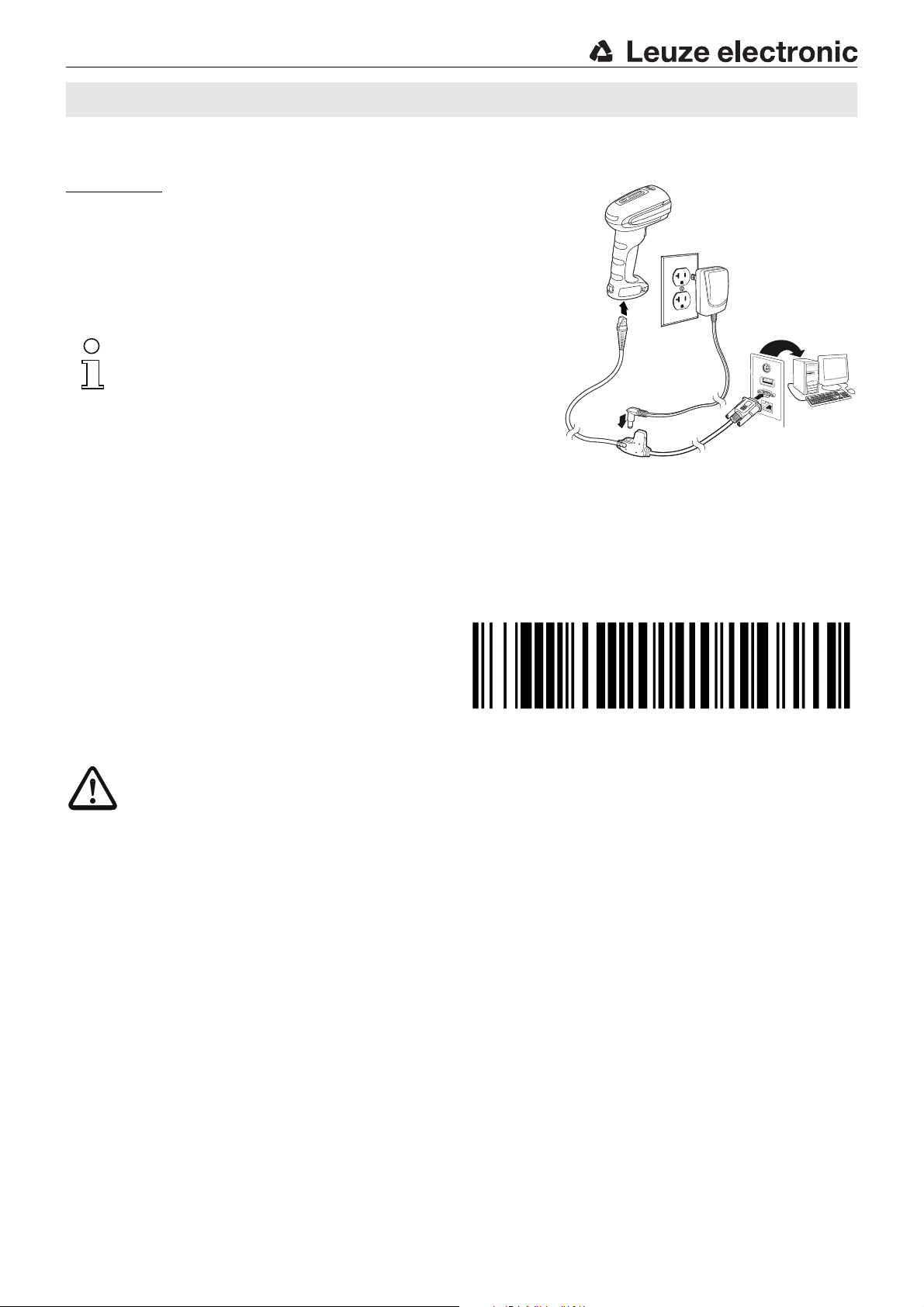
The adjacent figure shows the position of the cable connection on the scanner. The
individual steps for installing the cable on the scanner are described in the following.
1.To secure the interface cable to the scanner, proceed as follows:
Loosen the Phillips screw on the cable interlock on the bottom of the hand-held
scanner and, to open, push the cable interlock in the direction of the arrow to the
end position (). Insert the RJ 41 connector into the socket on the bottom of the
hand-held scanner until the connector engages.
2.To close, push the cable interlock back and secure the cable interlock by tightening
the Phillips screw ().
3.Connect the interface cable to the appropriate connection socket on the computer.
4.You may need a power supply unit for supplying voltage; alternatively, you can use
a cable which supplies voltage from the computer system. Use the pin assignments
(see "Electrical connection" on page 1) to select the appropriate cable for your
application.
5.Connect the power supply unit to the power socket (not necessary if voltage is
supplied from the computer).
6.Check the operational readiness of the scanner by pointing the scanning surface
towards a flat surface and pulling the trigger. A red target pattern as well as the red
illumination should now be visible. Now scan a sample label.
The scanner emits an audible signal to confirm that the label has been read; if
necessary, the data are now passed on to the computer.
Configuration
The hand-held scanner can always be configured using bar codes. To do this, the bar code must first be selected on the package
insert and then the trigger actuated in order to read the code. The configuration is then immediately accepted and executed.
Several of the most important configurations are listed in the following.
A second option is to configure the hand-held scanner with the USB and RS 232 interfaces with the aid of the EZ Config
PC program. You can download and install this program from our homepage at www.leuze.com.
The program can be used to make settings and transfer them to the hand-held scanner. The configuration can also be stored so
that it can be reused at a later time.
Further information on this can be found in the User's Guide for the IT 1910i/1911i.
The standard applications are described and summarized below.
Notice!
Additional information on the device and short instructions can be found on the Internet at www.leuze.com.
IT 1910i 2D-code hand-held scanner suitable for industrial use

IT 1910i - 01 2013/06
Resetting the IT 1910i to factory settings
To reset all parameters to factory settings, scan the adjacent
bar code.
Attention!
All settings are lost!!!
Trigger
To activate the read process, a trigger signal is to be sent via the serial RS 232 interface or USB interface (COM port emulation
only). The command is to be sent at the set baud rate, parity, and data and stop bits.
The command for activation is: SYN T CR ASCII decimal values: 022; 084; 013
To cancel read readiness, send a deactivation.
The command for deactivation is: SYN U CR ASCII decimal values: 022; 085; 013
Following a successful read operation, the IT 1910i deactivates itself.
The second option is activation via the built-in trigger button.
Configuration for the Leuze standard protocol
Scan the adjacent 2D-code.
The IT 1910i is set to the following transmission parameters:
RS 232 transmission with 9,600 baud, 8 data bits, 1 stop bit, no parity,
prefix <STX>, postfixes <CR><LF>.
IT 1910i

Leuze electronic GmbH + Co. KG In der Braike 1 D-73277 Owen Tel. +49 (0) 7021 573-0 IT 1910i - 01
Connecting the IT 1910 to the serial PC interface
Voltage supply via power supply unit with RS232 cable (part no. 50114517)
Required parts:
1x IT 1910i ER-3
1x 50114517 KB 232-1 IT190x
1x 50114525 Power supply unit
Notice!
Cable KB 232-1 IT190x (part no. 50114517) uses TTL-level
(0V…5V) for data transmission. As an alternative to this,
cable KB 232-2 IT190x (part no. 50115105) can be used.
This cable works with the regular RS232 level (-12V…+12V)
and therefore features a higher interference rejection. Both
cables are connection compatible.
Procedure:
1.Switch off the PC.
2.Connect the interface cable to a free COM port (RS 232) on the computer, to the IT 1910i as well as to the power supply unit
(if present).
3.Switch the PC back on.
4.Scan the adjacent bar code.
The IT 1910i is set to the following transmission
parameters:
RS 232 transmission with 115,200 baud, 8 data bits,
1 stop bit, no parity, postfixes <CR><LF>.
5.If necessary, adjust the transmission parameters of the
used COM port to those of the IT 1910i.
Attention!
We recommend connecting the IT 1910i directly to a PC or to the MA 21 or MA 41… connector units. If connecting to
other components, please note that a voltage level range is maintained on the data lines!
IT 1910i 2D-code hand-held scanner suitable for industrial use

IT 1910i - 01 2013/06
Connecting the IT 1910i to the MA 21
Required parts:
1x IT 1910i ER-3
1x 50114517 KB 232-1 IT190x
1x 50035421 KB 021 Z
1x 50030481 MA 21 100
Pin assignments KB021 Z:
Core color: Signal Terminal in the MA 21:
Brown (RXD) 26
White (TXD) 27
Blue (GND) 28
Red (VCC) 30
Black (GND) 31
Bare (shield) (PE) 21
Procedure:
1.Connect cable KB 021 Z to the MA 21… acc. to the above pin assignments.
2.Connect the interface cable to cable KB 021 Z.
3.Scan the adjacent 2D-code.
The IT 1910i is set to the following transmission parameters:
RS 232 transmission with 9600 baud, 7 data bits, 1 stop bit, even parity,
postfixes <CR><LF>.
Connecting the IT 1910i to the MA 2xxi
Required parts:
1x IT 1910i ER-3
1x 50114517 KB 232-1 IT190x
1x 50113397 KB JST-HS-300
1x MA 2xxi for the respective fieldbus system
Procedure:
1.Connect cable KB JST-HS-300 to the system connector on the MA 2xxi.
2.Connect the interface cable to cable KB JST-HS-300.
3.Scan the adjacent 2D-code.
The IT 1910i is set to the following transmission parameters:
RS 232 transmission with 9600 baud, 8 data bits, 1 stop bit, no parity,
postfixes <CR><LF>.
IT 1910i

Leuze electronic GmbH + Co. KG In der Braike 1 D-73277 Owen Tel. +49 (0) 7021 573-0 IT 1910i - 01
Connecting the IT 1910i to the PS/2 interface
The operation of the IT 1910i in keyboard emulation mode is described in this section. With this operating mode, a PC keyboard
is emulated. The read data are written directly into the currently activated program. The data can thereby be further processed
in all standard programs.
Required parts:
1x IT 1910i ER-3
1x 50114519 KB PS2-1 IT190x
Procedure:
1.Switch off the PC.
2.Disconnect the keyboard.
3.Plug in the IT 1910i hand-held scanner between the
keyboard and the PC.
4.Switch the PC back on.
5.Scan the 2D code shown below.
Disconnect
IT 1910i 2D-code hand-held scanner suitable for industrial use

IT 1910i - 01 2013/06
Connecting the IT 1910i to the USB interface (keyboard emulation)
The operation of the IT 1910i in keyboard emulation mode on a USB port is described in this section. With this operating mode,
a PC keyboard is emulated. The read data are written directly into the currently activated program. The data can thereby be
further processed in all standard programs.
Required parts:
1x IT 1910i ER-3
1x 50114521 KB USB-1 IT190x (3m, straight)
or
1x 50114523 KB USB-2 IT190x (5m, spiral)
Procedure:
1.Plug the IT 1910i hand-held scanner into a free
USB port.
2.The scanner acknowledges this connection with a
beep.
3.Scan the adjacent 2D code.
Connecting the IT 1910i to the USB interface (COM-port emulation)
The operation of the IT 1910i as a serial interface on a USB port is described in this chapter. With this operating mode, a COM
interface is emulated. The read data are sent to a new COM interface. The drivers with which this COM interface is emulated can
be downloaded from our homepage at www.leuze.com. Thus, the data can be processed further in programs which expect data
via COM interfaces.
Required parts:
1x IT 1910i ER-3
1x 50114521 KB USB-1 IT190x (3m, straight)
or
1x 50114523 KB USB-2 IT190x (5m, spiral)
Procedure:
1.Install the USB serial driver
(current version available at www.leuze.com).
2.Plug the IT 1910i hand-held scanner into a free
USB port.
3.The scanner acknowledges this connection with a
beep.
4.Scan the adjacent 2D code.
5.Open a terminal program or your program for the
serial interface, select the new COM port, and
make the following settings: baud rate 115,200,
8 data bits, 1 stop bit, no parity, postfix <CR>.
IT 1910i
Other manuals for IT 1910i
2
Table of contents
Other Leuze electronic Scanner manuals

Leuze electronic
Leuze electronic DCR 202i User manual

Leuze electronic
Leuze electronic RSL 450P User manual

Leuze electronic
Leuze electronic RSL 420P User manual

Leuze electronic
Leuze electronic CU405-2M12 User manual

Leuze electronic
Leuze electronic RSL 410 User manual

Leuze electronic
Leuze electronic RS4 User manual

Leuze electronic
Leuze electronic RS4 User manual

Leuze electronic
Leuze electronic rotoScan ROD4 plus Series User manual

Leuze electronic
Leuze electronic IT 6300 DPM Setup guide

Leuze electronic
Leuze electronic RSL 440 User manual