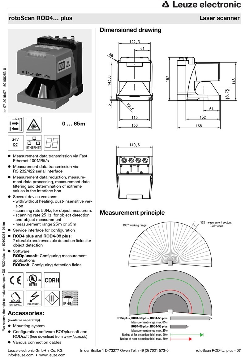
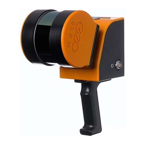
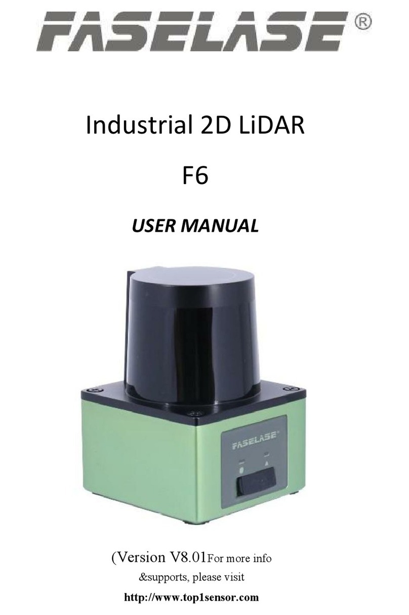
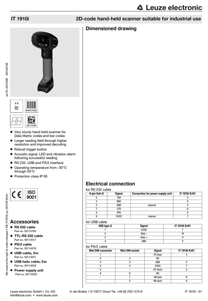
Leuze electronic rotoScan ROD4 plus Series User manual

rotoScan ROD4… plus
Laser scanner
en 05-2015/08 50127551
We reserve the right to
make technical changes
ORIGINAL OPERATING INSTRUCTIONS

Leuze electronic ROD4… plus 1
Inhaltsverzeichnis
1 General information ........................................................................................................... 6
1.1 Explanation of symbols ........................................................................................................ 6
1.2 Declaration of conformity ..................................................................................................... 6
2 Safety .................................................................................................................................. 7
2.1 Intended use ........................................................................................................................ 7
2.2 Foreseeable misuse............................................................................................................. 8
2.3 Competent persons.............................................................................................................. 8
2.4 Exemption of liability ............................................................................................................ 8
2.5 Laser safety notices ............................................................................................................. 9
2.6 Restrictions with regards to use ........................................................................................... 9
3 Description ....................................................................................................................... 10
3.1 Technical overview ............................................................................................................ 10
3.1.1 Object measurement ................................................................................................................... 11
3.1.2 Object detection (only ROD4 plus and ROD4-08 plus) ............................................................... 11
3.2 Operating principle............................................................................................................. 12
3.2.1 Measurement function ................................................................................................................. 13
3.2.2 Switching function (only ROD4 plus and ROD4-08 plus) ............................................................ 13
3.3 Special features of the ROD4…plus .................................................................................. 14
3.4 Application examples .........................................................................................................15
3.4.1 Object measurement: .................................................................................................................. 15
3.4.2 Object detection (only ROD4 plus and ROD4-08 plus) ............................................................... 16
4 Mounting........................................................................................................................... 19
5 Electrical connection ....................................................................................................... 20
5.1 Connecting the rotoScan ROD4…plus .............................................................................. 20
5.1.1 Connection functions Y1 to Y4 .................................................................................................... 21
5.1.2 Connector assignments for connection Y1.................................................................................. 22
5.1.3 Connector assignments for connection Y2 (Ethernet)................................................................. 22
5.1.4 Connector assignments for connection Y3 (service) ................................................................... 23
5.1.5 Connector assignments for connection Y4 (RS 232/RS 422)...................................................... 24
5.2 Functions of connection Y1................................................................................................ 25
5.2.1 Input circuit .................................................................................................................................. 25
5.2.2 Output circuit................................................................................................................................ 27
5.2.3 Restart ......................................................................................................................................... 28
5.3 Functions of connection Y2................................................................................................ 28
5.3.1 Y2 default settings ....................................................................................................................... 28
5.4 Functions of connection Y3................................................................................................ 29
5.4.1 Y3 default settings ....................................................................................................................... 29
5.5 Functions of connection Y4................................................................................................ 29
5.5.1 Y4 default settings ....................................................................................................................... 29
5.6 Connection......................................................................................................................... 30
5.6.1 Electrical supply........................................................................................................................... 30

2 ROD4… plus Leuze electronic
Inhaltsverzeichnis
5.6.2 Button for restarting (only ROD4 plus and ROD4-08 plus) ..........................................................30
5.7 Integration in the control system (only ROD4 plus and ROD4-08 plus)............................. 31
5.7.1 Connection example 1: without detection field pair switch...........................................................31
5.7.2 Connection example 2: with detection field pair switch ................................................................32
6 Start-up ............................................................................................................................. 33
6.1 Hardware and software requirements................................................................................ 33
6.2 Device configuration .......................................................................................................... 33
6.2.1 Configuring measurement applications with RODplussoft ...........................................................34
6.2.2 Selecting the measurement data protocol....................................................................................34
6.2.3 Defining detection fields with RODsoft
(only ROD4 plus and ROD4-08 plus)35
6.3 Screwing down and aligning the device............................................................................. 36
6.4 Switch on the device .......................................................................................................... 36
7 Testing and maintenance................................................................................................ 37
7.1 Test .................................................................................................................................... 37
7.2 Cleaning............................................................................................................................. 37
8 Delivery contents and accessories ................................................................................ 38
8.1 Type overview.................................................................................................................... 38
8.2 Accessories........................................................................................................................ 38
8.2.1 Pin assignments KB-014S-…-14..................................................................................................39
8.2.2 KB-ROD4plus… pin assignments ................................................................................................39
8.2.3 Pin assignment KB ET-…-SA-RJ45 (crossover cable) ................................................................39
8.2.4 Pin assignments KB ET-…-SA.....................................................................................................40
8.2.5 Pin assignments K-D M12A-8P-…...............................................................................................40
8.2.6 BT ROD4 mounting system..........................................................................................................41
9 Technical data .................................................................................................................. 42
9.1 Object measurement.......................................................................................................... 42
9.2 Detection field data (only ROD4 plus and ROD4-08 plus)................................................. 42
9.3 Electrical data .................................................................................................................... 43
9.4 Software............................................................................................................................. 44
9.5 Optical data........................................................................................................................ 44
9.6 Environmental data ............................................................................................................ 48
9.7 Dimensioned drawing ROD4…plus ................................................................................... 49
10 Status messages, errors and error rectification ........................................................... 50
10.1 Ethernet status indicator .................................................................................................... 50
10.2 ROD4…plus status indicator.............................................................................................. 51
10.2.1 Status displays .............................................................................................................................52
10.3 Diagnostic codes and causes ............................................................................................ 52
11 Appendix........................................................................................................................... 56
11.1 Terms and abbreviations ROD4…plus .............................................................................. 56

4 ROD4… plus Leuze electronic
Abbildungs- und Tabellenverzeichnis Leuze electronic
Table 3.1: Device types............................................................................................................... 10
Figure 3.1: Detection fields........................................................................................................... 11
Figure 3.2: Working range and angular resolution ....................................................................... 12
Figure 3.3: Operating principle ..................................................................................................... 12
Figure 3.4: Application example - gripping system....................................................................... 15
Figure 3.5: Application example - gantry crane ............................................................................ 15
Figure 3.6: Application example - dimension measurement......................................................... 16
Figure 3.7: Application example - service robot ........................................................................... 16
Figure 3.8: Application example - automatic parking garage ....................................................... 17
Figure 3.9: Application example - high-bay warehouse................................................................ 17
Figure 5.1: Connecting the rotoScan ROD4…plus....................................................................... 20
Table 5.1: Connections of the ROD4…plus – Y1 to Y4 .............................................................. 21
Table 5.2: Pin assignments for connection Y1 ............................................................................ 22
Table 5.3: Pin assignments for connection Y2 ............................................................................ 22
Table 5.4: Connection M12 to M12 (1:1) .................................................................................... 23
Table 5.5: Connection M12 to RJ45 (1:1) ................................................................................... 23
Table 5.6: Pin assignments for connection Y3 ............................................................................ 23
Table 5.7: Pin assignments for connection Y4 ............................................................................ 24
Figure 5.2: Inputs of interface Y1 ................................................................................................. 25
Figure 5.3: Example: Detection field pair switch for a DTS application ........................................ 26
Figure 5.4: Outputs of interface X1............................................................................................... 27
Figure 5.5: Connection example without detection field pair switch ............................................. 31
Figure 5.6: Connection example with detection field pair switch .................................................. 32
Figure 6.1: User interface of the RODsoft configuration software ................................................ 35
Figure 8.1: Dimensioned drawing BT ROD4 ................................................................................ 41
Table 9.1: Technical data - object measurement ........................................................................ 42
Table 9.2: Technical data - detection fields................................................................................. 42
Table 9.3: Technical data - electrical data................................................................................... 44
Table 9.4: Technical data - software ........................................................................................... 44
Table 9.5: Technical data - optical data ...................................................................................... 45
Figure 9.1: Object size/diffuse reflection as a function of distance for the ROD4… plus ............. 46
Figure 9.2: Typical beam dimensions with the ROD4…plus ........................................................ 47
Table 9.6: Technical data - environmental data .......................................................................... 48
Figure 9.3: Dimensioned drawing ROD4…plus............................................................................ 49
Figure 10.1: Ethernet status indicator............................................................................................. 50
Figure 10.2: ROD4…plus status indicator ...................................................................................... 51
Table 10.1: Status displays on the rotoScan ROD4…plus............................................................ 52
Table 10.2: ROD4…plus - Diagnostic codes and causes ............................................................. 53

Leuze electronic ROD4… plus 5
Abbildungs- und Tabellenverzeichnis

General information
4 ROD4… plus Leuze electronic
1 General information
1.1 Explanation of symbols
The symbols used in this technical description are explained below.
Attention!
This symbol precedes text messages which must strictly be observed. Failure to comply with
this information results in injuries to persons or damage to the equipment.
Attention Laser!
This symbol warns of possible danger caused by hazardous laser radiation.
The laser used in the ROD4…plus is a laser device of laser safety class 1 acc. to
DIN EN 60825-1. Observe the legal and local regulations applicable to the operation of laser
units.
Notice!
This symbol indicates text passages containing important information.
1.2 Declaration of conformity
The rotoScan ROD4… plus distance sensors have been manufactured observing current
European standards and guidelines.
Notice!
The corresponding declaration of conformity can be requested from the manufacturer.
The manufacturer of the product, Leuze electronic GmbH + Co. KG in D-73277 Owen/Teck,
possesses a certified quality assurance system in accordance with ISO 9001.
UL
US
C
LISTED

Safety
Leuze electronic ROD4… plus 5
TNT 35/7-24V
2Safety
This sensor was developed, manufactured and tested in line with the applicable safety stan-
dards. It corresponds to the state of the art.
2.1 Intended use
The ROD4… plus is an optical, two-dimensional measuring distance sensor.
Areas of application
The sensors of the ROD4… plus series are especially designed for the following areas of
application:
• Height/position detection
• Overshoot detection (e.g. in fully automatic parking systems)
• Buffing protection (e.g. for telpher lines)
• Contour measurement
• Packet measurement / volume measurement
Attention
For UL applications, use is only permitted in Class 2 circuits in accordance with the NEC
(National Electric Code).
CAUTION
Observe intended use!
Only operate the device in accordance with its intended use. The protection of per-
sonnel and the device cannot be guaranteed if the device is operated in a manner not
complying with its intended use.
Leuze electronic GmbH + Co. KG is not liable for damages caused by improper use.
Read the technical description before commissioning the device. Knowledge of this
technical description is an element of proper use.
NOTICE
Comply with conditions and regulations!
Observe the locally applicable legal regulations and the rules of the employer's liability
insurance association.
OPERATION NOTICE IN ACCORDANCE WITH UL CERTIFICATION:
CAUTION – Use of controls or adjustments or performance of procedures other than
those specified herein may result in hazardous light exposure.
ATTENTION ! Si d'autres dispositifs d'alignement que ceux préconisés ici sont util-
isés ou s'il est procédé autrement qu'indiqué, cela peut entraîner une exposition à
des rayonnements et un danger pour les personnes.

Safety
6 ROD4… plus Leuze electronic
2.2 Foreseeable misuse
Any use other than that defined under "Intended use" or which goes beyond that use is
considered improper use.
In particular, use of the device is not permitted in the following cases:
• Rooms with explosive atmospheres
• Circuits relevant to safety
• For medical purposes
2.3 Competent persons
Connection, mounting, commissioning and adjustment of the device must only be carried
out by competent persons.
Prerequisites for competent persons:
• They have a suitable technical education.
• They are familiar with the rules and regulations for occupational safety and safety at
work.
• They are familiar with the technical description of the device.
• They have been instructed by the responsible person on the mounting and operation
of the device.
Certified electricians
Electrical work must be carried out by a certified electrician.
Due to their technical training, knowledge and experience as well as their familiarity with
relevant standards and regulations, certified electricians are able to perform work on elec-
trical systems and independently detect possible dangers.
In Germany, certified electricians must fulfill the requirements of accident-prevention regu-
lations BGV A3 (e.g. electrician foreman). In other countries, there are respective regula-
tions that must be observed.
2.4 Exemption of liability
Leuze electronic GmbH + Co. KG is not liable in the following cases:
• The device is not being used properly.
• Reasonably foreseeable misuse is not taken into account.
• Mounting and electrical connection are not properly performed.
• Changes (e.g., constructional) are made to the device.
NOTICE
Do not modify or otherwise interfere with the device.
Do not carry out modifications or otherwise interfere with the device.
The device must not be tampered with and must not be changed in any way.
The device must not be opened. There are no user-serviceable parts inside.
Repairs must only be performed by Leuze electronic GmbH + Co. KG.

Safety
Leuze electronic ROD4… plus 7
TNT 35/7-24V
2.5 Laser safety notices
2.6 Restrictions with regards to use
• Glass, highly reflective materials such as mirrors (luminosity coefficient > 10,000%)
as well as objects which do not reflect any light back to the sensor could falsify the
measurement value. Additional notices can be found in chapter 9.5.
• Do not expose the ROD4… plus to flying sparks (e.g. welding sparks); the front cover,
among other parts of the system, will be damaged.
• Vapours, smoke, dust and all particles visible in the air could affect the measurement
values and cause the semiconductor outputs to switch off.
• Avoid large temperature fluctuations.
• If a protective housing is provided for the sensor, the detection must not occur through
additional window material (plastic, glass, etc.).
• Physical contact with the front cover of the sensor and the six diffused-light windows
is to be avoided.
ATTENTION, INVISIBLE LASER RADIATION – LASER CLASS 1
The device fulfills the EN 60825-1:2007 safety regulations for a product in laser class 1
as well as the U.S. 21 CFR 1040.10 regulations with deviations corresponding to "Laser
Notice No. 50" from June 24th, 2007.
Observe the applicable statutory and local laser protection regulations.
The device must not be tampered with and must not be changed in any way.
There are no user-serviceable parts inside the device.
Repairs must only be performed by Leuze electronic GmbH + Co. KG.

Description
8 ROD4… plus Leuze electronic
3 Description
3.1 Technical overview
Table 3.1: Device types
The ROD4…plus is an optical, two-dimensional measuring distance sensor. It could also be
referred to as an optical, area radar unit. The device periodically transmits light pulses within
an scanning angle of 190° via a rotating deflector unit.
If the pulses are incident upon objects or obstacles, the light is reflected and then received
and analysed by the ROD4…plus. From the propagation time of the radiated light and the
current angle of the deflector unit, the ROD4…plus unit calculates the exact coordinates of
the object.
These data can be used by the ROD4…plus for 2 different areas of application:
1. Object measurement
An angular resolution of 0.36° allows the distance to objects to be measured with an
accuracy of 5mm within the measurement range drawn in figure 3.1.
2. Object detection (only ROD4 plus and ROD4-08 plus)
Detection field contours can be defined within the detection fields drawn in figure 3.1.
If an object is located within these detection field contours, this is reported by the
ROD4…plus to the configurable switching outputs.
For object measurement tasks, the device is configured using the RODplussoft software.
Designation Design Part no.
ROD4 plus For object detection / object measurement, scanning rate
25scans/s 50106481
ROD4-08 plus
For object detection / object measurement, scanning rate
25scans/s,
with heating, dust-insensitive
50106480
ROD4-50 plus For object measurement, scanning rate 50scans/s 50113226
ROD4-56 plus For object measurement, scanning rate 50scans/s, with
heating 50129795
ROD4-58 plus For object measurement, scanning rate 50scans/s
with heating, dust-insensitive 50113225

Description
Leuze electronic ROD4… plus 9
TNT 35/7-24V
If the ROD4…plus is to be used for object detection, device configuration is performed with
RODsoft.
Figure 3.1: Detection fields
The ROD4 plus and ROD4-08 plus can be used both on vehicles (mobile object detection
for vehicles) as well as in stationary applications on systems and machines (object detec-
tion/measurement).
The long-range and contactless measurement principle makes the ROD4…plus unit a
universally applicable measuring system.
3.1.1 Object measurement
In measurement operation, the ROD4…plus transfers all measured distance data to a
primary control or to a PC. An object contour can be calculated from the measurement data.
The RODplussoft software can be used to configure the Ethernet interface (Y2) and the
serial interface (Y4) for outputting the measurement data. Furthermore, the type of protocol
used for measurement data transfer can be set.
In addition, preprocessing of the measurement data can be performed in the ROD4…plus:
• The data quantity can be reduced in order to match the quantity to the possible trans-
mission speed
• The measurement data can be filtered on the basis of user-defined specifications
For further information on measurement data preparation, please refer to the RODplussoft
manual.
3.1.2 Object detection (only ROD4 plus and ROD4-08 plus)
For object detection, detection fields are defined with the RODsoft software.
If an object or obstacle is located within these detection fields, a stop function is executed.
The ROD4 plus and ROD4-08 plus can detect objects with diameters greater than 20mm at
a distance of up to 4.0m, even if the surface of the given object is dark. Larger objects are
detected in the far detection field at a distance of up to 50m.
Measurement range ROD4-08 plus, ROD4-58 plus: max. 25m
Meas. range ROD4 plus, ROD4-50 plus, ROD4-56 plus: max. 65m
Radius of near detection field: max. 30m
Radius of far detection field: max. 50m

Description
10 ROD4… plus Leuze electronic
3.2 Operating principle
The working range of the ROD4…plus (190°) is divided into 0.36° angular segments (cor-
responds to 529 measurement values).
Figure 3.2: Working range and angular resolution
Bundled light pulses are generated by a laser diode with coupled transmission optics. These
light pulses are reflected by a rotating mirror in such a way that a light pulse is emitted every
40ms in all angular segments (scanning rate: 25scans/s or
50scans/s). If the light pulse is incident upon an object, it is reflected and subsequently
detected and analysed by the ROD4…plus.
Figure 3.3: Operating principle
The ROD4…plus works on the principle of pulse propagation time measurement. The light
pulse propagation time is a direct measurement of the distance to the object.
The measurement values are transferred via interfaces Y2 and Y4 as 16bit data (2 bytes).
One scan over the working range returns 529 measurement values (from angle -5.04° to
angle +185.04° with 0.36° angular resolution). Thus, each individual measurement value
corresponds to an angular segment of 0.36°. The measurement values are sequentially
numbered from segment 0 (-5.04°) to segment 528 (+185.04°), see figure 3.2.
0.36° angular resolution
Working range
Angular segment
528
Angular segment 0

Description
Leuze electronic ROD4… plus 11
TNT 35/7-24V
Reference measurement
A reference measurement cyclically controls the measurement function. The following func-
tions are checked on each rotation of the mirror by means of a test object located inside of
the device:
• optical systems (e.g. transmitter and receiver)
• hardware, software, etc.
Window monitoring
A total of six light axes monitor the degree of soiling of the window. During this procedure,
the results are compared with two reference sensors. Moreover, these reference sensors
are used for temperature compensation and ageing monitoring.
3.2.1 Measurement function
You can configure the measurement functions of the ROD4…plus yourself with the supplied
RODplussoft software.
You can define the measurement mode (continuous/individual measurement), define
measurement segments (start/stop angle, angular resolution), as well as define the type of
measurement data transfer (in polar or cartesian coordinates) and pre-process and filter the
measurement results in the ROD4…plus.
3.2.2 Switching function (only ROD4 plus and ROD4-08 plus)
You can configure the switching functions of the ROD4 plus and ROD4-08 plus yourself with
the supplied RODsoft software. In addition to the device configuration, the software can also
be used to define detection field pairs, to adapt them to the given application and to save the
same in the ROD4 plus or ROD4-08 plus.
Four reversible detection field pairs make possible an optimal adaptation to the applications.
A detection field pair is considered to be the combination of both a near and far detection
field. The near and far detection fields are represented by different colours in the RODsoft
configuration software: near = red, far = green.
The image of the surroundings generated during the scan process is compared with the
specified detection field contours. If an object violates a detection field for a least one scan
(40ms), a corresponding, user-specific reaction is triggered.

Description
12 ROD4… plus Leuze electronic
3.3 Special features of the ROD4…plus
•ROD4 plus and ROD4-08 plus for object detection / object measurement,
scanning rate 25 scans/s
•ROD4-50 plus, ROD4-56 plus and ROD4-58 plus for object measurement,
scanning rate 50 scans/s
• Working range up to 190°
• Small construction size (W x D x H: 141mm x 168mm x 167mm)
• Low weight (2.3kg)
• Low current consumption
• Two interfaces for measurement data transfer:
• Ethernet at socket Y2
• RS 232/RS 422 at connector Y4
• Easy-to-use RODsoft and RODplussoft configuration software (object detection with
ROD4 plus and ROD4-08 plus)
• Measurement data processing:
• X,Y coordinate transformation
• Area configuration
• Measurement data filtering: minimum and maximum values
• Online commands
• ROD4plusandROD4-08plus:
• Four freely programmable near detection fields (up to maximum 30m)
• Four freely programmable far detection fields (up to maximum 50m)

Description
Leuze electronic ROD4… plus 13
TNT 35/7-24V
3.4 Application examples
The following examples can be considered typical areas of application for the ROD4…plus.
3.4.1 Object measurement:
Gripping system
Dimension and position measurement for gripping operations
Figure 3.4: Application example - gripping system
Gantry crane
ROD4…plus for positioning a gantry crane
Figure 3.5: Application example - gantry crane

Description
14 ROD4… plus Leuze electronic
Pallet measurement
Dimension measurement in materials handling
Figure 3.6: Application example - dimension measurement
3.4.2 Object detection (only ROD4 plus and ROD4-08 plus)
Driverless transportation system
ROD4…plus as the "eye" of a service robot
Figure 3.7: Application example - service robot

Description
Leuze electronic ROD4… plus 15
TNT 35/7-24V
Automatic parking garage
Overshoot and dimension detection of cars to prevent damage to the car
Figure 3.8: Application example - automatic parking garage
High-bay warehouse
Overshoot detection for collision prevention with high-bay storage devices
Figure 3.9: Application example - high-bay warehouse

Description
16 ROD4… plus Leuze electronic
Other applications
• Buffing protection (e.g. for telpher lines)
• Overshoot detection (e.g. in fully automatic parking systems)
• Detection / counting of persons
• Room security / façade monitoring
• Access control
• Contour measurement
• Packet measurement / volume measurement
•etc.

Mounting
Leuze electronic ROD4… plus 17
TNT 35/7-24V
4 Mounting
Mount the ROD4…plus so that the area being monitored is within the measurement range
of the device.
Attention!
Because of the optical scanning principle, only objects with good reflective properties are
detected directly in front of the sensor window.
Physical damage to the sensor (e.g. due to collision or climbing on) should be prevented by
using a protective enclosure. If using an enclosure, the entire front cover of the device must,
however, remain unobstructed.
In order for the ROD4…plus to function optimally, it must be mounted in a favourable posi-
tion. You should make every effort to observe the following points:
• Position the ROD4…plus such that it has maximum protection.
• The mounting location and the electrical supply should be located as close as possi-
ble to one another.
• The ROD4…plus is to be mounted so that the area being monitored is within the
measurement range of the device.
• The mounting position of the ROD4… plus must offer protection from humidity, soil-
ing, as well as temperatures below 0°C (ROD4 plus, ROD4-50 plus) or -20°C (ROD4-
08 plus, ROD4-56 plus, ROD4-58 plus) and above 50°C.
• The mounting location is to be selected such that the possibilities for mechanical
damage are minimised. Exposed locations are to be equipped with additional protec-
tive guards or loop guards.
• Reinforcements, enclosures, mounting alcoves and other machine elements must not
result in an obstruction in the field of vision.
• Retro-reflectors or very reflective surfaces, such as certain metals or ceramics, are to
be avoided near the detection fields and at the height of the scanning plane as these
may result in measurement errors.
• To ensure a constant detection height at every point in the measurement range, the
ROD4…plus, and thus the beam plane, is to be mounted parallel to the reference
plane.
• If the ROD4…plus is used without start disable or start test with automatic start/
restart, a start warning (optical/acoustic) is to be provided.
• The ROD4…plus must not be used as a climbing aid. If there is a risk of this, a suit-
able, inclined (45°) protector is to be mounted.
The device dimensions and the reference of the scanning plane to the device edges can be
found in the dimensioned drawing (see figure 9.3 on page 47). Here, the zero point for the
distance measurement is the axis of rotation of the rotating mirror (ain figure 9.3). Mounting
system BT ROD4…plus, see chapter 8.2.6.
Notice!
Under certain circumstances, a larger measurement inaccuracy may occur with strongly re-
flective backgrounds (e.g. retro-reflectors).

Electrical connection
18 ROD4… plus Leuze electronic
5 Electrical connection
5.1 Connecting the rotoScan ROD4…plus
To configure the ROD4…plus, connect the control cable (KB-014-5000-14, plug Y1) to the
power supply and the interface cable (KB-ROD4 plus-…, socket Y3) to the PC or laptop.
Furthermore, interface Y2 for transferring the process data should be connected to the PC
or the same network as the PC.
Notice!
To configure the measurement function with RODplussoft, Y2 or Y4 may be connected
instead of Y3. For the initial configuration of the interfaces, it is, however, recommended that
Y3 be connected.
To transfer the process data with RODplussoft, Y2 or Y4 may be selected. Following the
initial configuration, subsequent configuration can be performed in parallel with process data
transfer via a single interface (Y2 or Y4).
To configure the detection function with RODsoft, it is absolutely necessary to connect Y3.
Before commissioning the system, please check the pin assignments, the wiring, the supply
voltage and the safeguarding. In spite of the robust housing and fittings of the ROD4…plus,
which include various internal safety mechanisms, damages resulting from misconnection
cannot be excluded.
Figure 5.1: Connecting the rotoScan ROD4…plus
Attention!
Should you not need one of the interfaces, close the respective connector with a blank plug.
If a connector remains open, the ROD4…plus no longer has degree of protection IP 65.
bc
a
aConnection for configuration only
bPlug Y1 (14-pin, M16)
cSocket Y3 (5-pin, M12)
Other manuals for rotoScan ROD4 plus Series
1
This manual suits for next models
5
Table of contents
Other Leuze electronic Scanner manuals

Leuze electronic
Leuze electronic RSL 450P User manual

Leuze electronic
Leuze electronic rotoScan ROD4 plus Series User manual

Leuze electronic
Leuze electronic RSL 410 User manual

Leuze electronic
Leuze electronic IT 1910i User manual

Leuze electronic
Leuze electronic RSL 440 User manual

Leuze electronic
Leuze electronic IT 6300 DPM Setup guide

Leuze electronic
Leuze electronic RS4 User manual

Leuze electronic
Leuze electronic DCR 202i User manual

Leuze electronic
Leuze electronic CU405-2M12 User manual

Leuze electronic
Leuze electronic RS4 User manual