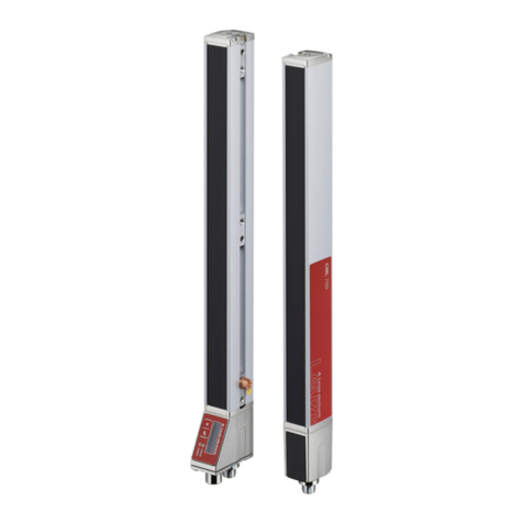
Leuze electronic MLD 300 User manual

MLD 300, MLD 500
Multiple Light Beam Safety Devices
Original operating instructions
EN 2012/12 - 607342
We reserve the right to
make technical changes

Leuze electronic MLD 300, MLD 500 3
1 About this document. . . . . . . . . . . . . . . . . . . . . . . . . . . . . . . . . . . . . . . . . . . . . . . . . . . . 6
1.1 Used symbols and signal words . . . . . . . . . . . . . . . . . . . . . . . . . . . . . . . . . . . . . . . . . . . . . . . . . . . . 6
1.2 Checklists . . . . . . . . . . . . . . . . . . . . . . . . . . . . . . . . . . . . . . . . . . . . . . . . . . . . . . . . . . . . . . . . . . . . . 6
2 Safety . . . . . . . . . . . . . . . . . . . . . . . . . . . . . . . . . . . . . . . . . . . . . . . . . . . . . . . . . . . . . . . 7
2.1 Approved purpose and foreseeable improper operation . . . . . . . . . . . . . . . . . . . . . . . . . . . . . . . . . . 7
2.1.1 Proper use . . . . . . . . . . . . . . . . . . . . . . . . . . . . . . . . . . . . . . . . . . . . . . . . . . . . . . . . . . . . . . . . . . . . . 7
2.1.2 Using the laser alignment aid . . . . . . . . . . . . . . . . . . . . . . . . . . . . . . . . . . . . . . . . . . . . . . . . . . . . . . 8
2.1.3 Foreseeable misuse . . . . . . . . . . . . . . . . . . . . . . . . . . . . . . . . . . . . . . . . . . . . . . . . . . . . . . . . . . . . . 9
2.2 Competent persons . . . . . . . . . . . . . . . . . . . . . . . . . . . . . . . . . . . . . . . . . . . . . . . . . . . . . . . . . . . . . 10
2.3 Responsibility for safety. . . . . . . . . . . . . . . . . . . . . . . . . . . . . . . . . . . . . . . . . . . . . . . . . . . . . . . . . . 10
2.4 Exemption of liability . . . . . . . . . . . . . . . . . . . . . . . . . . . . . . . . . . . . . . . . . . . . . . . . . . . . . . . . . . . . 10
3 Device description . . . . . . . . . . . . . . . . . . . . . . . . . . . . . . . . . . . . . . . . . . . . . . . . . . . . 11
3.1 Device overview. . . . . . . . . . . . . . . . . . . . . . . . . . . . . . . . . . . . . . . . . . . . . . . . . . . . . . . . . . . . . . . . 11
3.2 Connection system . . . . . . . . . . . . . . . . . . . . . . . . . . . . . . . . . . . . . . . . . . . . . . . . . . . . . . . . . . . . . 12
3.2.1 AS-i parameter port . . . . . . . . . . . . . . . . . . . . . . . . . . . . . . . . . . . . . . . . . . . . . . . . . . . . . . . . . . . . . 13
3.3 Display elements . . . . . . . . . . . . . . . . . . . . . . . . . . . . . . . . . . . . . . . . . . . . . . . . . . . . . . . . . . . . . . . 13
3.3.1 Operating indicators on the transmitter . . . . . . . . . . . . . . . . . . . . . . . . . . . . . . . . . . . . . . . . . . . . . . 13
3.3.2 Operation indicators on the receiver . . . . . . . . . . . . . . . . . . . . . . . . . . . . . . . . . . . . . . . . . . . . . . . . 14
3.3.3 7-segment display at the receiver . . . . . . . . . . . . . . . . . . . . . . . . . . . . . . . . . . . . . . . . . . . . . . . . . . 15
3.3.4 Multicolor indicator. . . . . . . . . . . . . . . . . . . . . . . . . . . . . . . . . . . . . . . . . . . . . . . . . . . . . . . . . . . . . . 16
3.4 Integrated laser alignment aid . . . . . . . . . . . . . . . . . . . . . . . . . . . . . . . . . . . . . . . . . . . . . . . . . . . . . 16
4 Functions . . . . . . . . . . . . . . . . . . . . . . . . . . . . . . . . . . . . . . . . . . . . . . . . . . . . . . . . . . . 18
4.1 Start/restart interlock . . . . . . . . . . . . . . . . . . . . . . . . . . . . . . . . . . . . . . . . . . . . . . . . . . . . . . . . . . . . 18
4.2 Contactor monitoring . . . . . . . . . . . . . . . . . . . . . . . . . . . . . . . . . . . . . . . . . . . . . . . . . . . . . . . . . . . . 19
4.3 Signal output . . . . . . . . . . . . . . . . . . . . . . . . . . . . . . . . . . . . . . . . . . . . . . . . . . . . . . . . . . . . . . . . . . 19
4.4 Range shift. . . . . . . . . . . . . . . . . . . . . . . . . . . . . . . . . . . . . . . . . . . . . . . . . . . . . . . . . . . . . . . . . . . . 19
4.5 MultiScan mode . . . . . . . . . . . . . . . . . . . . . . . . . . . . . . . . . . . . . . . . . . . . . . . . . . . . . . . . . . . . . . . . 19
4.6 Periodic function test . . . . . . . . . . . . . . . . . . . . . . . . . . . . . . . . . . . . . . . . . . . . . . . . . . . . . . . . . . . . 19
4.7 Muting . . . . . . . . . . . . . . . . . . . . . . . . . . . . . . . . . . . . . . . . . . . . . . . . . . . . . . . . . . . . . . . . . . . . . . . 20
4.7.1 Timing controlled 2-sensor muting. . . . . . . . . . . . . . . . . . . . . . . . . . . . . . . . . . . . . . . . . . . . . . . . . . 20
4.7.2 Sequence controlled 2-sensor muting . . . . . . . . . . . . . . . . . . . . . . . . . . . . . . . . . . . . . . . . . . . . . . . 21
4.7.3 Timing controlled 4-sensor muting. . . . . . . . . . . . . . . . . . . . . . . . . . . . . . . . . . . . . . . . . . . . . . . . . . 21
4.7.4 Muting timeout . . . . . . . . . . . . . . . . . . . . . . . . . . . . . . . . . . . . . . . . . . . . . . . . . . . . . . . . . . . . . . . . . 22
4.7.5 Muting restart. . . . . . . . . . . . . . . . . . . . . . . . . . . . . . . . . . . . . . . . . . . . . . . . . . . . . . . . . . . . . . . . . . 23
4.7.6 Alternative connection for second muting signal . . . . . . . . . . . . . . . . . . . . . . . . . . . . . . . . . . . . . . . 23
4.7.7 Muting-enable . . . . . . . . . . . . . . . . . . . . . . . . . . . . . . . . . . . . . . . . . . . . . . . . . . . . . . . . . . . . . . . . . 24
4.7.8 Partial muting. . . . . . . . . . . . . . . . . . . . . . . . . . . . . . . . . . . . . . . . . . . . . . . . . . . . . . . . . . . . . . . . . . 25
4.7.9 Muting operating modes . . . . . . . . . . . . . . . . . . . . . . . . . . . . . . . . . . . . . . . . . . . . . . . . . . . . . . . . . 25
5 Applications . . . . . . . . . . . . . . . . . . . . . . . . . . . . . . . . . . . . . . . . . . . . . . . . . . . . . . . . . 27
5.1 Access guarding . . . . . . . . . . . . . . . . . . . . . . . . . . . . . . . . . . . . . . . . . . . . . . . . . . . . . . . . . . . . . . . 27
6 Mounting. . . . . . . . . . . . . . . . . . . . . . . . . . . . . . . . . . . . . . . . . . . . . . . . . . . . . . . . . . . . 30
6.1 Arrangement of transmitter and receiver . . . . . . . . . . . . . . . . . . . . . . . . . . . . . . . . . . . . . . . . . . . . . 30
6.1.1 Arrangement of 1-beam safety sensors. . . . . . . . . . . . . . . . . . . . . . . . . . . . . . . . . . . . . . . . . . . . . . 30
6.1.2 Beam heights and ranges . . . . . . . . . . . . . . . . . . . . . . . . . . . . . . . . . . . . . . . . . . . . . . . . . . . . . . . . 30
6.1.3 Calculating the safety distance . . . . . . . . . . . . . . . . . . . . . . . . . . . . . . . . . . . . . . . . . . . . . . . . . . . . 31
6.1.4 Calculation of the safety distance for vertical protective fields with reaching over . . . . . . . . . . . . . 31
6.1.5 Minimum distance to reflective surfaces . . . . . . . . . . . . . . . . . . . . . . . . . . . . . . . . . . . . . . . . . . . . . 34
6.1.6 Preventing mutual interference between adjacent devices . . . . . . . . . . . . . . . . . . . . . . . . . . . . . . . 35
6.2 Arrangement of the muting sensors. . . . . . . . . . . . . . . . . . . . . . . . . . . . . . . . . . . . . . . . . . . . . . . . . 36

Leuze electronic MLD 300, MLD 500 4
6.2.1 Basic information . . . . . . . . . . . . . . . . . . . . . . . . . . . . . . . . . . . . . . . . . . . . . . . . . . . . . . . . . . . . . . . 36
6.2.2 Selecting optoelectronic muting sensors . . . . . . . . . . . . . . . . . . . . . . . . . . . . . . . . . . . . . . . . . . . . . 37
6.2.3 Minimum distance for optoelectronic muting sensors . . . . . . . . . . . . . . . . . . . . . . . . . . . . . . . . . . . 37
6.2.4 Arrangement of the muting sensors for timing controlled 2-sensor muting . . . . . . . . . . . . . . . . . . . 37
6.2.5 Arrangement of the muting sensors for sequence controlled 2-sensor muting . . . . . . . . . . . . . . . . 39
6.2.6 Arrangement of the muting sensors for timing controlled 4-sensor muting . . . . . . . . . . . . . . . . . . . 41
6.3 Mounting the safety sensor . . . . . . . . . . . . . . . . . . . . . . . . . . . . . . . . . . . . . . . . . . . . . . . . . . . . . . . 43
6.3.1 Suitable mounting locations. . . . . . . . . . . . . . . . . . . . . . . . . . . . . . . . . . . . . . . . . . . . . . . . . . . . . . . 43
6.3.2 BT-240 swivel mount (optional) . . . . . . . . . . . . . . . . . . . . . . . . . . . . . . . . . . . . . . . . . . . . . . . . . . . . 44
6.3.3 BT-P40 clamp bracket (optional) . . . . . . . . . . . . . . . . . . . . . . . . . . . . . . . . . . . . . . . . . . . . . . . . . . . 45
7 Electrical connection . . . . . . . . . . . . . . . . . . . . . . . . . . . . . . . . . . . . . . . . . . . . . . . . . . 46
7.1 Pin assignment transmitter and receiver . . . . . . . . . . . . . . . . . . . . . . . . . . . . . . . . . . . . . . . . . . . . . 46
7.1.1 Standard pin assignment . . . . . . . . . . . . . . . . . . . . . . . . . . . . . . . . . . . . . . . . . . . . . . . . . . . . . . . . . 46
7.1.2 AS-i pin assignment. . . . . . . . . . . . . . . . . . . . . . . . . . . . . . . . . . . . . . . . . . . . . . . . . . . . . . . . . . . . . 49
7.1.3 AS-i signal assignment . . . . . . . . . . . . . . . . . . . . . . . . . . . . . . . . . . . . . . . . . . . . . . . . . . . . . . . . . . 49
7.2 Selecting contactor monitoring and start/restart interlock . . . . . . . . . . . . . . . . . . . . . . . . . . . . . . . . 50
7.3 Selecting the muting operating modes . . . . . . . . . . . . . . . . . . . . . . . . . . . . . . . . . . . . . . . . . . . . . . 52
7.3.1 Operating mode 1 (muting):. . . . . . . . . . . . . . . . . . . . . . . . . . . . . . . . . . . . . . . . . . . . . . . . . . . . . . . 54
7.3.2 Operating mode 2 (muting timeout 8 h): . . . . . . . . . . . . . . . . . . . . . . . . . . . . . . . . . . . . . . . . . . . . . 56
7.3.3 Operating mode 3 (sequence controlled 2-sensor muting):. . . . . . . . . . . . . . . . . . . . . . . . . . . . . . . 57
7.3.4 Operating mode 4 (sequence controlled 2-sensor muting with muting timeout 8 h):. . . . . . . . . . . . 58
7.3.5 Operating mode 5 (muting-enable):. . . . . . . . . . . . . . . . . . . . . . . . . . . . . . . . . . . . . . . . . . . . . . . . . 59
7.3.6 Operating mode 6 (partial muting): . . . . . . . . . . . . . . . . . . . . . . . . . . . . . . . . . . . . . . . . . . . . . . . . . 60
8 Setting the device into service . . . . . . . . . . . . . . . . . . . . . . . . . . . . . . . . . . . . . . . . . . . 62
8.1 Switching on . . . . . . . . . . . . . . . . . . . . . . . . . . . . . . . . . . . . . . . . . . . . . . . . . . . . . . . . . . . . . . . . . . 62
8.2 AS-i connection start-up . . . . . . . . . . . . . . . . . . . . . . . . . . . . . . . . . . . . . . . . . . . . . . . . . . . . . . . . . 62
8.2.1 Initial start-up . . . . . . . . . . . . . . . . . . . . . . . . . . . . . . . . . . . . . . . . . . . . . . . . . . . . . . . . . . . . . . . . . . 62
8.2.2 Exchange of AS-i slaves . . . . . . . . . . . . . . . . . . . . . . . . . . . . . . . . . . . . . . . . . . . . . . . . . . . . . . . . . 62
8.3 Aligning the safety sensor . . . . . . . . . . . . . . . . . . . . . . . . . . . . . . . . . . . . . . . . . . . . . . . . . . . . . . . . 63
8.4 Aligning without integrated laser alignment aid . . . . . . . . . . . . . . . . . . . . . . . . . . . . . . . . . . . . . . . . 63
8.5 Aligning with integrated laser alignment aid . . . . . . . . . . . . . . . . . . . . . . . . . . . . . . . . . . . . . . . . . . 64
8.5.1 Required devices and tools . . . . . . . . . . . . . . . . . . . . . . . . . . . . . . . . . . . . . . . . . . . . . . . . . . . . . . . 65
8.5.2 Aligning without UDC device columns and without UMC Deflecting Mirror Columns . . . . . . . . . . . 65
8.5.3 Aligning with UDC device columns and with UMC Deflecting Mirror Columns . . . . . . . . . . . . . . . . 67
8.6 Start/restart button . . . . . . . . . . . . . . . . . . . . . . . . . . . . . . . . . . . . . . . . . . . . . . . . . . . . . . . . . . . . . . 70
8.6.1 Unlocking start/restart interlock . . . . . . . . . . . . . . . . . . . . . . . . . . . . . . . . . . . . . . . . . . . . . . . . . . . . 70
8.6.2 Muting restart. . . . . . . . . . . . . . . . . . . . . . . . . . . . . . . . . . . . . . . . . . . . . . . . . . . . . . . . . . . . . . . . . . 70
9 Testing . . . . . . . . . . . . . . . . . . . . . . . . . . . . . . . . . . . . . . . . . . . . . . . . . . . . . . . . . . . . . 72
9.1 Before the initial start-up and following modifications . . . . . . . . . . . . . . . . . . . . . . . . . . . . . . . . . . . 72
9.1.1 Checklist – before the initial start-up . . . . . . . . . . . . . . . . . . . . . . . . . . . . . . . . . . . . . . . . . . . . . . . . 73
9.2 To be performed periodically by competent persons. . . . . . . . . . . . . . . . . . . . . . . . . . . . . . . . . . . . 74
9.3 To be performed daily by the operator. . . . . . . . . . . . . . . . . . . . . . . . . . . . . . . . . . . . . . . . . . . . . . . 74
9.3.1 Check list – daily or at change of shift . . . . . . . . . . . . . . . . . . . . . . . . . . . . . . . . . . . . . . . . . . . . . . . 74
9.4 Annual testing of safe switch-off of the AS-i connection . . . . . . . . . . . . . . . . . . . . . . . . . . . . . . . . . 75
10 Maintenance. . . . . . . . . . . . . . . . . . . . . . . . . . . . . . . . . . . . . . . . . . . . . . . . . . . . . . . . . 76
11 Rectifying the fault . . . . . . . . . . . . . . . . . . . . . . . . . . . . . . . . . . . . . . . . . . . . . . . . . . . . 77
11.1 What to do in case of failure? . . . . . . . . . . . . . . . . . . . . . . . . . . . . . . . . . . . . . . . . . . . . . . . . . . . . . 77
11.2 Operating displays of the LEDs . . . . . . . . . . . . . . . . . . . . . . . . . . . . . . . . . . . . . . . . . . . . . . . . . . . . 77
11.3 Error messages 7-segment display . . . . . . . . . . . . . . . . . . . . . . . . . . . . . . . . . . . . . . . . . . . . . . . . . 78
11.4 Multicolor indicator. . . . . . . . . . . . . . . . . . . . . . . . . . . . . . . . . . . . . . . . . . . . . . . . . . . . . . . . . . . . . . 80
Leuze electronic MLD 300, MLD 500 5
11.5 Error message query via AS-Interface. . . . . . . . . . . . . . . . . . . . . . . . . . . . . . . . . . . . . . . . . . . . . . . 81
12 Disposing . . . . . . . . . . . . . . . . . . . . . . . . . . . . . . . . . . . . . . . . . . . . . . . . . . . . . . . . . . . 82
13 Service and support . . . . . . . . . . . . . . . . . . . . . . . . . . . . . . . . . . . . . . . . . . . . . . . . . . . 83
14 Technical data . . . . . . . . . . . . . . . . . . . . . . . . . . . . . . . . . . . . . . . . . . . . . . . . . . . . . . . 84
14.1 General specifications . . . . . . . . . . . . . . . . . . . . . . . . . . . . . . . . . . . . . . . . . . . . . . . . . . . . . . . . . . . 84
14.2 Dimensions, weights . . . . . . . . . . . . . . . . . . . . . . . . . . . . . . . . . . . . . . . . . . . . . . . . . . . . . . . . . . . . 87
14.3 Dimensional drawings: accessories. . . . . . . . . . . . . . . . . . . . . . . . . . . . . . . . . . . . . . . . . . . . . . . . . 89
15 Ordering information and accessories . . . . . . . . . . . . . . . . . . . . . . . . . . . . . . . . . . . . . 93
16 EC Declaration of Conformity. . . . . . . . . . . . . . . . . . . . . . . . . . . . . . . . . . . . . . . . . . . 119

About this document
Leuze electronic MLD 300, MLD 500 6
1 About this document
1.1 Used symbols and signal words
Table 1.1: Warning symbols and signal words
Table 1.2: Other symbols
Table 1.3: Terms and abbreviations
1.2 Checklists
The checklists see chapter 9 „Testing“serve as a reference for the machine manufacturer or supplier. They
replace neither testing of the complete machine or system prior to the initial start-up nor their periodic
testing by a competent person. The checklists contain minimum testing requirements. Depending on the
application, other tests may be necessary.
Symbol indicating dangers to persons
NOTICE Signal word for property damage
Indicates dangers that may result in property damage if the measures for danger
avoidance are not followed.
CAUTION Signal word for minor injury
Indicates dangers that may result in minor injury if the measures for danger avoid-
ance are not followed.
WARNING Signal word for severe injury
Indicates dangers that may result in severe or fatal injury if the measures for danger
avoidance are not followed.
DANGER Signal word for life-threatening danger
Indicates dangers with which serious or fatal injury is imminent if the measures for
danger avoidance are not followed.
Symbol for tips
Text passages with this symbol provide you with further information.
Symbols for action steps
Text passages with this symbol instruct you to perform actions.
AOPD Active Optoelectronic Protective Device
Active Optoelectronic Protective Device
EDM External Device Monitoring
MTTF Mean time to a dangerous failure
Mean Time To Failure
OSSD Output Signal Switching Device
SIL Safety Integrity Level
RES Start/REStart interlock
PFH Probability of a dangerous failure per hour
Probability of dangerous Failure per Hour
PL Performance Level

Safety
Leuze electronic MLD 300, MLD 500 7
2 Safety
Before using the safety sensor, a risk assessment must be performed according to valid standards (e.g.
EN ISO 14121, EN ISO 12100-1, EN ISO 13849-1, IEC 61508, EN IEC 62061). The result of the risk
assessment determines the required safety level of the safety sensor see table 2.1. For mounting, oper-
ating and testing, this document as well as all applicable national and international standards, regulations,
rules and directives must be observed. Relevant and supplied documents must be observed, printed out
and handed to affected persons.
Before working with the safety sensor, completely read and understand the documents applicable to
your task.
In particular, the following national and international legal regulations apply for the start-up, technical
inspections and work with safety sensors:
• Machinery directive 2006/42/EC
• Low voltage directive 2006/95/EC
• Electromagnetic compatibility directive 2004/108/EC
• Use of Work Equipment Directive 89/655/EEC supplemented by Directive 95/63 EC
• OSHA 1910 Subpart O
• Safety regulations
• Accident-prevention regulations and safety rules
• Ordinance on Industrial Safety and Health and Labor Protection Act
• Product Safety Law (ProdSG)
2.1 Approved purpose and foreseeable improper operation
2.1.1 Proper use
• The safety sensor may only be used after it has been selected in accordance with the respectively
applicable instructions and relevant standards, rules and regulations regarding labor protection and
safety at work, and after it has been installed on the machine, connected, commissioned, and
checked by a competent person see chapter 2.2 „Competent persons“.
• When selecting the safety sensor it must be ensured that its safety-related capability meets or
exceeds the required performance level PLr ascertained in the risk assessment.
The following table shows the safety-related characteristic parameters of the MLD 300 and MLD 500
series.
For safety-related information you may also contact the local authorities (e.g., industrial inspec-
torate, employer's liability insurance association, labor inspectorate, occupational safety and
health authority).
WARNING
A running machine may result in serious injury!
Make certain that the safety sensor is correctly connected and that the protective function of the pro-
tective device is ensured.
Make certain that, during all conversions, maintenance work and inspections, the system is securely
shut down and protected against being restarted again.

Safety
Leuze electronic MLD 300, MLD 500 8
Table 2.1: Models and safety-related parameters for the MLD 300 and MLD 500 series
• The safety sensor protects persons at access points or at hazard locations of machines and plants.
• The safety sensor detects persons only when they enter the danger zone but cannot tell whether
there are any persons inside the danger zone. For this reason, a start/restart interlock in the safety
chain is essential.
• The construction of the safety sensor must not be altered. When manipulating the safety sensor, the
protective function is no longer guaranteed. Manipulating the safety sensor also voids all warranty
claims against the manufacturer of the safety sensor.
• The safety sensor must be tested regularly by competent persons see chapter 2.2 „Competent
persons“.
• The safety sensor must be exchanged after a maximum of 20 years. Repairs or the exchange of
parts subject to wear and tear do not extend the service life.
2.1.2 Using the laser alignment aid
The optional internal laser alignment aid is available for transmitter-receiver systems.
Laser alignment aids must only be switched on for the purpose of alignment or testing the alignment of
transmitters, receivers and Deflecting Mirror Columns.
Do not switch on the laser if persons are present in the laser path.
Inform persons in the vicinity before embarking on alignment work
with lasers.
Variant MLD 312 (for external
testing)
MLD 300 MLD 500
Type in accordance with
EN IEC 61496-1, -2
Type 2 Type 2 Type 4
SIL in accordance with IEC 61508 SIL 2 SIL 3
SILCL in accordance with
EN IEC 62061
- SILCL 2 SILCL 3
Performance Level (PL) in accor-
dance with EN ISO 13849-1
up to PL d a) PL d PL e
Category in accordance with
EN ISO 13849-1
category 2 category 3 category 4
Probability of a dangerous failure
per hour
PFHd=1.2 x 10-
8 b) Leuze electronic
safety monitoring
device
PFHd=1.2 x 10⁻⁸ PFHd=6.6 x 10⁻⁹c)
MTTFd204 years
a) with a respective safety monitoring device (e.g., Leuze electronic MSI-T), with DCavg ³ medium
b) during an external test with DC > 90 %, e.g., with a MSI-T
c) or 6.0 x 10E-9 for MLD/AS-i
WARNING
The laser light source corresponds to laser class 2 according to EN 60825-1. Extended looking into the
beam path may damage the eye's retina.
Never look directly into the laser beam or into the direction of reflected beams.
WARNING
Adjustment work with lasers must be carried out by competent and instructed persons only.

Safety
Leuze electronic MLD 300, MLD 500 9
After switch-on the laser lights up for about 10 minutes. Do not leave the installation location during this
time.
Interrupt the laser beam using a non-transparent, non-reflective object if the laser beam has inadver-
tently been pointed at a human.
Note the current legal and local laser protection regulations according to EN 60825-1.
Laser warning signs and notice signs
There are laser warning signs near the laser beam egress pointsee figure 2.1.
Attach the supplied self-adhesive notice signs clearly visible at the safety sensor and on the device col-
umn see figure 2.2.
If used in the U.S., attach the respective notice sign.
2.1.3 Foreseeable misuse
Any use other than that defined under the “Approved purpose” or which goes beyond that use is consid-
ered improper use.
In principle, the safety sensor is not suitable as a protective device for use in the following cases:
• danger of objects being expelled or hot or dangerous liquids spurting from the danger zone
• applications in explosive or easily flammable atmospheres
• reachability of the location of hazard by hand from the mounting location of the safety sensor
• detection of the presence of persons in danger zones
Figure 2.1: Laser warning sign
Figure 2.2: Self-adhesive notice signs
USA
DE
GB
FR
LASERSTRAHLUNG
NICHT IN DEN STRAHL BLICKEN
LASER KLASSE 2
DIN EN 60825-1: 2008-05
Max. Leistung:
Wellenlänge: 650 nm
1 mW
LASER LIGHT
DO NOT STARE INTO BEAM
CLASS 2 LASER PRODUCT
DIN EN 60825-1: 2008-05
Max. Output:
Wavelength:
1 mW
650 nm
RAYONNEMENT
NE PAS REGARDER DANS LE FAISCEAU
APPAREIL A LASER DE CLASSE 2
DIN EN 60825-1: 2008-05
Puissance max.:
Longueur d'onde émis:
1 mW
650 nm
LASER LIGHT
DO NOT STARE INTO BEAM
CLASS 2 LASER PRODUCT
IEC 60825-1: 2007
Max. Output:
Wavelength:
1 mW
650 nm
Complies with 21 CFR 1040.10

Safety
Leuze electronic MLD 300, MLD 500 10
2.2 Competent persons
Prerequisites for competent persons:
• They have a suitable technical education.
• They know the rules and regulations for occupational safety, safety at work and safety technology
and can assess the safety of the machine.
• They know the instructions for the safety sensor and the machine.
• They have been instructed by the responsible person on the mounting and operation of the machine
and of the safety sensor.
2.3 Responsibility for safety
Manufacturer and operating company must ensure that the machine and implemented safety sensor func-
tion properly and that all affected persons are adequately informed and trained.
The type and content of all imparted information must not lead to unsafe actions by users.
The manufacturer of the machine is responsible for:
• safe machine construction
• safe implementation of the safety sensor
• imparting all relevant information to the operating company
• adhering to all regulations and directives for the safe starting-up of the machine
The company operating the machine is responsible for:
• instructing the operator
• maintaining the safe operation of the machine
• adhering to all regulations and directives for occupational safety and safety at work
• Regular testing by instructed persons
2.4 Exemption of liability
Leuze electronic GmbH + Co. KG is not liable in the following cases:
• safety sensor is not used as intended
• safety notices are not adhered to
• reasonably foreseeable misuse is not taken into account
• mounting and electrical connection are not properly performed
• proper function is not tested see chapter 9 „Testing“
• changes (e.g., constructional) are made to the safety sensor

Device description
Leuze electronic MLD 300, MLD 500 11
3 Device description
The safety sensors of the MLD 300 and MLD 500 series are active optoelectronic protective devices, each
with two failsafe OSSDs. They satisfy the following standards:
• Performance Level PL d and PL e in accordance with EN ISO 13849-1
• Safety category 2, 3 and 4 in accordance with EN ISO 13849-1
• Safety Integrity Levels SIL 3 and SIL 2 in accordance with IEC 61508 and EN IEC 62061
• Type 2 and type 4 in accordance with EN IEC 61496-1, prEN IEC 61496-2
The safety sensors are available as transmitter-receiver systems (1-, 2-, 3- and 4-beam) or as transceiver
systems (2- and 3-beam). All device versions satisfy laser class 1 acc. to EN 60825-1 and EN 62471-2006.
They are protected against overvoltage and overcurrent acc. to IEC 60204-1 (safety class 3). Infrared
beams are modulated in specially shaped pulse packets in such a way that they can be distinguished from
ambient light (e.g. welding sparks, warning lights) and, thus, not be affected by it.
3.1 Device overview
The following tables provide an overview over the device models' functions of the MLD 300 and MLD 500
series.
Table 3.1: Models and functions of the MLD 300 series
Table 3.2: Models and functions of the MLD 500 series
Transmit-
ter
Receiver/transceiver
MLD 300 MLD 310 MLD 312 MLD 320 MLD 330
MLD 335
OSSDs 2122
Automatic start/restart
RES a)
EDM b) b)
Signal output
LED display
7-segment display
Integrated muting
a) RES selectable
b) EDM selectable
Transmitter Receiver/transceiver
MLD 500 MLD 500/
AS-i
MLD 510 MLD 520 MLD 530
MLD 535
MLD 500/
AS-i
OSSDs 2 2 2
Automatic start/restart
RES a)
EDM b) b)
Signal output

Device description
Leuze electronic MLD 300, MLD 500 12
The transmitter-receiver system consists of one transmitter and one receiver.
The transceiver system consists of an active transceiver (transmitter/receiver) and a passive Deflecting
Mirror (no electrical connection, deflects the light beams by 2 x 90°).
3.2 Connection system
Transmitter and receiver are equipped with M12 round pin plugs that differ in pin number depending on
device version:
LED display
7-segment display
Integrated muting
a) RES selectable
b) EDM selectable
Transmitter Receiver/transceiver
MLD 500 MLD 500/
AS-i
MLD 510 MLD 520 MLD 530
MLD 535
MLD 500/
AS-i
Figure 3.1: Transmitter-receiver system
Figure 3.2: Transceiver system

Device description
Leuze electronic MLD 300, MLD 500 13
3.2.1 AS-i parameter port
The parameter port can only be addressed by the bus master. MLD/A1 delivers a safety at work-specific
code sequence which the AS-i Safety Monitor teaches in and permanently monitors. In addition, the bus
master has the option of reading the interfering signal via the parameter port and controlling an internal or
external muting display via the cyclical output data see chapter 7.1.2 „AS-i pin assignment“.
3.3 Display elements
The display elements of the safety sensors simplify start-up and fault analysis.
3.3.1 Operating indicators on the transmitter
There is a green LED at each light axis of the transmitter serving as a function indicator.
Device version Number of pins on the receiver/trans-
ceiver
Number of pins on the trans-
mitter
MLD 310, MLD 510 5-pin plug 5-pin plug
MLD 312 5-pin plug 5-pin plug
MLD 320, MLD 520 8-pin plug 5-pin plug
MLD 330, MLD 530 8-pin plug and 5-pin socket 5-pin plug
MLD 335, MLD 535 8-pin plug and 8-pin socket 5-pin plug
MLD 500/AS-i, MLD 510/AS-i 5-pin plug 5-pin plug
MLD 510-...I/O 5-pin plug and separate 5-pin socket for
external muting indicator
5-pin plug
1LED
2 Beam marking
Figure 3.3: Green LED on each transmitter light axis for function indication
1
2
Transmitter

Device description
Leuze electronic MLD 300, MLD 500 14
Table 3.3: Meaning of the LED
3.3.2 Operation indicators on the receiver
The receiver has a LED (LED1, red or green). The following device models have additional display
elements at the receiver:
• MLD 320, MLD 520: LED2 (yellow)
• MLD 330, MLS 335, MLD 530, MLD 535: LED2 (yellow), 7-segment display, muting indicator
(optional)
Table 3.4: Meaning of LED1
LED Description
Green Transmitted beam active
Off Fault (transmitted beam inactive)
1LED1
2 Symbol for OSSD
3 Interface symbol (MLD 330, MLD 335, MLD 530, MLD 535)
4LED2
5 Symbol RES
6 Beam marking
Figure 3.4: Operation indicators on the receiver
4
1
6
5
2
3
Receiver
LED1 Meaning
Red OSSD off
Green OSSD on
Red slowly flashing (approx. 1 Hz) External fault
Red flashing fast (approx. 10 Hz) Internal fault
Green slowly flashing (approx. 1 Hz) OSSD on, weak signal

Device description
Leuze electronic MLD 300, MLD 500 15
Table 3.5: Meaning of the LED2 displays
Table 3.6: Meaning of LED2 for safety sensor with integrated AS-i interface (AS-i model)
3.3.3 7-segment display at the receiver
(MLD 330, MLD 335, MLD 530, MLD 535)
The 7-segment display shows the number of the operating mode (1 to 6) and assist in the detailed fault
diagnosis see chapter 11 „Rectifying the fault“. For the identification of the fault, the fault's respective letter
is displayed first followed by the number code. The display is repeated cyclically. An AutoReset is carried
out after 10 s, with an unauthorized restart being impossible.
LED2 Meaning
Yellow Start/restart interlock locked (restart required)
LED2 Meaning
Red AS-i slave is not communicating with AS-i master
Green AS-i slave is not communicating with AS-i master
Yellow flashing AS-i slave has invalid address 0
Red flashing AS-i slave device fault or AS-i connection defective
Flashing green, red alternately Periphery fault
Off No voltage
1LED1
2 Symbol for OSSD
3 Interface symbol
4 7-segment display
5LED2
6 RES symbol
7 Beam marking
Figure 3.5: 7-segment display on MLD 330, MLD 335, MLD 530, MLD 535 receiver
5
1
7
6
2
3
4
Receiver

Device description
Leuze electronic MLD 300, MLD 500 16
Table 3.7: Meaning of the 7-segment display
3.3.4 Multicolor indicator
(Optional for MLD 320, MLD 330, MLD 335, MLD 520, MLD 530, MLD 535 as well as for MLD 510/AS-i,
MLD 510-...M/A)
The multicolor indicator signals the OSSD state see table 11.1. In addition, during muting a constant white
light signals that muting has been started correctly and that the protective function has been bridged. A
muting error is signalized by blinking see table 11.2.
3.4 Integrated laser alignment aid
(Optional for MLD 310, MLD 312, MLD 320, MLD 510, MLD 520)
The laser alignment aid is optionally available for transmitter-receiver systems. There is a red light laser
on the transmitter side of each light axis. The laser beams can all be switched on simultaneously via
MagnetKey. The sensor for the MagnetKey is located next to the transmitter's first light axis. The laser
beams remain active for approx. 10 min and then switch off automatically see chapter 8.5 „Aligning with
integrated laser alignment aid“.
Display Meaning
1...6 Operating mode selected during standard operation
F... Device fault, internal fault
E... Fault, external fault see chapter 11 „Rectifying the fault“
U... Usage Event, e.g., U52: muting time limit elapsed see
chapter 11 „Rectifying the fault“
With AS-i devices, the integrated muting indicator must be set externally, e.g. via asimon config-
uration and diagnostics software.
1 Muting indicators
2 Beam marking
Figure 3.6: Muting indicator on the receiver
2
1
Alternatively, the laser can also be activated for approx. 10 min by a signal on the transmitter. To
do this, a change has to be made from 0 V to 24 V on PIN2, e.g. with a connected button see
table 7.1.

Device description
Leuze electronic MLD 300, MLD 500 17
1 Transmitter
2 Laser
3 MagnetKey
4 Beam marking
Figure 3.7: MagnetKey activation position at first light axis of the transmitter
CAUTION
Danger! Class 2 laser beams!
Never look directly into the laser beam. This can cause damage to the eye.
1
4
3
2

Functions
Leuze electronic MLD 300, MLD 500 18
4 Functions
Table 4.1: Overview of the safety functions
Table 4.2: Functions of the different versions
4.1 Start/restart interlock
(MLD 320, MLD 330, MLD 335, MLD 520, MLD 530, MLS 535)
The start/restart interlock prevents automatic release of the safety circuits and automatic start-up of the
system (e.g. if the protective field is again clear or if an interruption in the voltage supply is restored). The
operator must make certain that no people are present in the danger zone before the system is manually
re-enabled with the start/restart button see chapter 8.6.1 „Unlocking start/restart interlock“.
Function Description
Stop function safety-related; initiated by the protective device
RES (start/restart interlock) prevents automatic restart; forces manual confirmation
EDM (contactor monitoring) monitors the N/C contacts of downstream positive-guided
contactors and relays
Muting targeted, proper bridging of the protective function
Periodic function test safety-related; initiated and tested, e.g. by an external
safety monitoring device
Function MLD 310,
MLD 510
MLD 312,
testable
MLD 320,
MLD 520
MLD 330,
MLD 530
MLD 335,
MLD 535
OSSDs 21222
Automatic start/restart
RES a)
EDM a)
EDM, selectable
Signal output
LED display
7-segment display
2-sensor muting, parallel and sequential
b)
Timing controlled 4-sensor muting
Laser alignment aid
(optional for transmitter-receiver systems)
Configurable operating modes
External test
a) Selectable
b) with shortened filter times: 0.1 s instead of 3 s

Functions
Leuze electronic MLD 300, MLD 500 19
4.2 Contactor monitoring
(MLD 320, MLD 330, MLD 335, MLD 520, MLD 530, MLS 535)
The electro-sensitive protective equipment monitors the feedback circuits of the connected contactors.
The signal at the EDM input is compared to the state of the OSSDs. The feedback circuit must be open
while the OSSDs are switched on (high-impedance). When the OSSDs are switched off, 0 V is applied at
the EDM input see chapter 7.2. The reaction at the EDM input with respect to the OSSDs is delayed by
maximum 500 ms (contactors).
4.3 Signal output
(MLD 320, MLD 330, MLD 335, MLD 520, MLD 530, MLS 535)
The receiver or transceiver features a signal output.PIN1 reports the state of the OSSDs.
Table 4.3: Signaling of the state of the OSSDs
4.4 Range shift
With transmitter/receiver systems, the range can be adjusted on PIN4 of the transmitter. It is possible to
shift between 50 m and 20 m.
Table 4.4: Range shift on PIN4 of the transmitter
4.5 MultiScan mode
Only after an interruption of the protective field continues for several consecutive scans is the system
switched off. This increases the availability (e.g. in the event of minor physical shocks).
4.6 Periodic function test
(MLD 312)
The receiver/transceiver of the MLD 312 is equipped with a test input for the periodic function test by an
external safety monitoring device (e.g. Leuze electronic MSI-T). Signal response and timing see figure 4.1.
Voltage on signal output (PIN1) OSSD
0 V On
24 V Off
PIN4 Transceiver
0 V 50 m
24 V approx. 20 m
When using the external Test Monitoring Unit, make certain that the test duration does not ex-
ceed 150 ms.

Functions
Leuze electronic MLD 300, MLD 500 20
4.7 Muting
By means of muting, the protective function can be temporarily and properly suppressed, e.g. if objects
are to be transported through the protective field. During this time, the OSSDs remain in the ON state in
spite of interruption of one or more beams.
Muting is only initiated automatically and via two mutually independent muting signals. The muting indi-
cator illuminates continuously during the entire duration of muting operation. End of muting operation is
forced as soon as the preset maximum duration (muting timeout) is exceeded.
Following malfunctions or operationally related interruptions (e.g. power failure, violation of the concur-
rency condition during timing controlled 2-sensor muting on activation of the muting sensors), the system
can be manually reset with the start/restart button and overridden.
4.7.1 Timing controlled 2-sensor muting
The two muting sensors MS1 and MS2 are arranged in such a way that the beams cross and the process
can automatically activate both sensors (within 4 s). As a result, an object can be transported through the
protective field in both directions. The intersection point must be within the danger zone to prevent muting
from being unintentionally triggered.
If muting was properly activated, it remains active even during brief interruptions of a single sensor signal.
On foil-wrapped objects, for example, brief signal interruptions can occur—particularly with light scanners.
These short signal interruptions are, therefore, filtered out for up to max. 3 s (MLD 335, MLD 535: 300 ms).
If both muting sensors are inactive simultaneously, timing controlled 2-sensor muting ends.
Figure 4.1: Reaction of the OSSD switching output of the MLD 312 to an external test request
For series connection of multiple type 2 devices (e.g. MLD 312 and type 2 Light Beam Safety
Devices), cross connection between test signal and switching output is to be avoided. For this
purpose, connecting cables must be laid so that no cross connections can occur, or test signal
and switching output must be laid in separate cables.
max.150 ms
high-impedance
OSSD-Output +24 V
high-impedance or 0 V
Input + 24 V
6 ms 6 ms
1 Danger zone
MS1 Muting sensor 1
MS2 Muting sensor 2
tTime frame in which both muting sensors must be activated (4 s)
Figure 4.2: Timing controlled 2-sensor muting–arrangement of
the muting sensors and timing
t
MS1
MS2
MS1
MS2
Muting
1

Functions
Leuze electronic MLD 300, MLD 500 21
4.7.2 Sequence controlled 2-sensor muting
Sequence controlled 2-sensor muting is particularly well suited for exiting danger zones, especially if there
is only limited space available outside of the danger zone. In this case, material transport is only permis-
sible in one direction due to the arrangement of the muting sensors. Muting sensors MS1 and MS2 are
positioned within the danger zone and arranged so that they are activated in sequence. Once the muting
area is clear again, the muting state ends with a delay of 5 s. For sequence controlled 2-sensor muting,
there are no temporal expectations between MS1 and MS2. The only conditions that must be observed is
that, within eight hours of activation of MS1, MS2 must also be activated. In this way transported goods
can exit the protective field in a timely manner.
Sequence controlled 2-sensor muting can also be used if objects that are positioned close to one another
are to be moved through the protective field. The distance between the individual objects must, however,
be large enough that at least one muting sensor is free between two successive objects for at least 300 ms.
4.7.3 Timing controlled 4-sensor muting
(MLD 335, MLD 535)
Timing controlled 4-sensor muting is used when the muting sensor light beams should not cross, but instead
must be parallel, due to special application situations, e.g. with reflective materials or under disruption.
1 Danger zone
MS1 Muting sensor 1
MS2 Muting sensor 2
t8 h
Figure 4.3: Sequence controlled 2-sensor muting–arrangement of the muting sensors and timing
WARNING
Risk of death by through incorrect arrangement of the muting sensors!
Only select sequence controlled 2-sensor muting for material exits (see chapter 6.2.5).
1 Danger zone
MS1 Muting sensor 1
MS2 Muting sensor 2
t<8 h
Figure 4.4: Muting for tight sequences of objects–arrangement of the muting sensors and timing
1
MS2 MS1
MS1
MS2
Muting
<5 s
t
t
MS1
MS2
Muting n
>300 ms
Muting
n+1
1
MS2 MS1
<5 s
This manual suits for next models
1
Table of contents
Other Leuze electronic Security Sensor manuals

Leuze electronic
Leuze electronic MLC 300 Series User manual

Leuze electronic
Leuze electronic ERS200-M0C3-M20-HLR User manual

Leuze electronic
Leuze electronic MLC 500 Series User manual

Leuze electronic
Leuze electronic CU411-RS4 User manual

Leuze electronic
Leuze electronic SD4T 14 Quick start guide

Leuze electronic
Leuze electronic CRT448 User manual

Leuze electronic
Leuze electronic OPSL 775 User manual

Leuze electronic
Leuze electronic MLC 510 AS-i Host/Guest User manual

Leuze electronic
Leuze electronic MLC 520 User manual

Leuze electronic
Leuze electronic RSL 430 User manual