Leuze electronic SOLID-2 Series Quick start guide

SOLID-2
Safety Light Curtain
607374 - 2015/04
Subject to change wit-
hout prior notice
CONNECTING AND OPERATING INSTRUCTIONS
Original Instructions

2 SOLID-2 Leuze electronic
Review-Stand, , Mittwoch, 8. April 2015
DEUTSCH ENGLISH FRANÇAIS ITALIANO ESPAÑOL NEDERLANDS
Notes on Connecting and Operating Instructions
This connecting and operating instructions manual contains information on the proper use
of SOLID-2 Safety Light Curtains in accordance with its intended purpose.
All the information contained herein, in particular the safety notes, need to be carefully
observed.
Notes regarding safety and warnings are marked by this symbol .
Notes regarding important pieces of information are marked by the symbol .
This connecting and operating instructions manual must be stored carefully. It must be
available for the entire operating time of the SOLID-2.
The Leuze electronic GmbH + Co. KG is not liable for damages caused by improper use.
Acquaintance with these instructions is an element of the knowledge required for proper
use.
©Reprints and reproduction, in whole or in part, are permitted only with the explicit
permission of
Leuze electronic GmbH + Co. KG
In der Braike 1
D-73277 Owen - Teck / Germany
Telefon +49 (0) 7021 / 573-0
Fax +49 (0) 7021 / 573-199
www.leuze.com

Leuze electronic SOLID-2 3
TNT 35/7-24V
Review-Stand, , 8. April 2015
DEUTSCHENGLISHFRANÇAISITALIANOESPAÑOLNEDERLANDS
Contents
1 General . . . . . . . . . . . . . . . . . . . . . . . . . . . . . . . . . . . . . . . . . . . . . . . . . . . . . . . . . . . . . . . . . . . . . 5
1.1 Certifications . . . . . . . . . . . . . . . . . . . . . . . . . . . . . . . . . . . . . . . . . . . . . . . . . . . . . . . . . . . . 5
1.2 Symbols and terms . . . . . . . . . . . . . . . . . . . . . . . . . . . . . . . . . . . . . . . . . . . . . . . . . . . . . . . 6
1.3 Selecting a SOLID-2 . . . . . . . . . . . . . . . . . . . . . . . . . . . . . . . . . . . . . . . . . . . . . . . . . . . . . . 8
1.3.1 SOLID-2 Safety Light Curtains . . . . . . . . . . . . . . . . . . . . . . . . . . . . . . . . . . . . . . . . 8
2Safety. . . . . . . . . . . . . . . . . . . . . . . . . . . . . . . . . . . . . . . . . . . . . . . . . . . . . . . . . . . . . . . . . . . . . . 9
2.1 Approved purpose and foreseeable improper operation . . . . . . . . . . . . . . . . . . . . . . . . . 9
2.1.1 Proper use . . . . . . . . . . . . . . . . . . . . . . . . . . . . . . . . . . . . . . . . . . . . . . . . . . . . . . . . 9
2.1.2 Foreseeable misuse . . . . . . . . . . . . . . . . . . . . . . . . . . . . . . . . . . . . . . . . . . . . . . . 10
2.2 Competent personnel . . . . . . . . . . . . . . . . . . . . . . . . . . . . . . . . . . . . . . . . . . . . . . . . . . . . 11
2.3 Responsibility for safety . . . . . . . . . . . . . . . . . . . . . . . . . . . . . . . . . . . . . . . . . . . . . . . . . . 11
2.4 Exemption of liability . . . . . . . . . . . . . . . . . . . . . . . . . . . . . . . . . . . . . . . . . . . . . . . . . . . . . 11
2.5 Additional safety instructions for access guarding with SOLID-2 . . . . . . . . . . . . . . . . . . 11
3 System design and selectable functions . . . . . . . . . . . . . . . . . . . . . . . . . . . . . . . . . . . . . . . . 13
3.1 The opto-electronic protective device . . . . . . . . . . . . . . . . . . . . . . . . . . . . . . . . . . . . . . . 13
3.2 Functions of the Transmitter . . . . . . . . . . . . . . . . . . . . . . . . . . . . . . . . . . . . . . . . . . . . . . . 13
3.2.1 Transmission channel . . . . . . . . . . . . . . . . . . . . . . . . . . . . . . . . . . . . . . . . . . . . . . 13
3.2.2 Internal or external testing . . . . . . . . . . . . . . . . . . . . . . . . . . . . . . . . . . . . . . . . . . 14
3.3 Selectable function of the Receiver Standard and Extended . . . . . . . . . . . . . . . . . . . . . 14
3.3.1 Transmission channel . . . . . . . . . . . . . . . . . . . . . . . . . . . . . . . . . . . . . . . . . . . . . . 14
3.4 Additional functions of the Receiver Extended . . . . . . . . . . . . . . . . . . . . . . . . . . . . . . . . 15
3.4.1 Start/restart interlock (RES) . . . . . . . . . . . . . . . . . . . . . . . . . . . . . . . . . . . . . . . . . . 15
3.4.2 Contactor monitoring (EDM) . . . . . . . . . . . . . . . . . . . . . . . . . . . . . . . . . . . . . . . . . . . . . . 16
4 Display elements . . . . . . . . . . . . . . . . . . . . . . . . . . . . . . . . . . . . . . . . . . . . . . . . . . . . . . . . . . . . 17
4.1 Transmitter status displays . . . . . . . . . . . . . . . . . . . . . . . . . . . . . . . . . . . . . . . . . . . . . . . . 17
4.2 Receiver status displays . . . . . . . . . . . . . . . . . . . . . . . . . . . . . . . . . . . . . . . . . . . . . . . . . . 18
4.2.1 7-segment display . . . . . . . . . . . . . . . . . . . . . . . . . . . . . . . . . . . . . . . . . . . . . . . . 18
4.2.2 LED displays . . . . . . . . . . . . . . . . . . . . . . . . . . . . . . . . . . . . . . . . . . . . . . . . . . . . . 19
5 Installation . . . . . . . . . . . . . . . . . . . . . . . . . . . . . . . . . . . . . . . . . . . . . . . . . . . . . . . . . . . . . . . . . 21
5.1 Calculating minimum distances . . . . . . . . . . . . . . . . . . . . . . . . . . . . . . . . . . . . . . . . . . . . 21
5.1.1 Safety distance for safeguarding danger points . . . . . . . . . . . . . . . . . . . . . . . . . 21
5.1.2 Safety distance for safeguarding danger areas . . . . . . . . . . . . . . . . . . . . . . . . . . 23
5.1.3 Safety distance and beam heights for access guarding . . . . . . . . . . . . . . . . . . . . . . . . 25
5.1.4 Minimum distance from reflective surfaces . . . . . . . . . . . . . . . . . . . . . . . . . . . . . . . . . . 27
5.2 Mounting notes . . . . . . . . . . . . . . . . . . . . . . . . . . . . . . . . . . . . . . . . . . . . . . . . . . . . . . . . . 28
5.3 Mechanical mounting . . . . . . . . . . . . . . . . . . . . . . . . . . . . . . . . . . . . . . . . . . . . . . . . . . . . 29
5.4 Mounting types . . . . . . . . . . . . . . . . . . . . . . . . . . . . . . . . . . . . . . . . . . . . . . . . . . . . . . . . . 29
5.4.1 Standard mounting . . . . . . . . . . . . . . . . . . . . . . . . . . . . . . . . . . . . . . . . . . . . . . . . 29
5.4.2 Option: Mounting with swiveling brackets . . . . . . . . . . . . . . . . . . . . . . . . . . . . . . . . . . . 30
5.4.3 Option: Side mounting . . . . . . . . . . . . . . . . . . . . . . . . . . . . . . . . . . . . . . . . . . . . . 30
6 Electrical connection . . . . . . . . . . . . . . . . . . . . . . . . . . . . . . . . . . . . . . . . . . . . . . . . . . . . . . . . 31
6.1 M12 connection . . . . . . . . . . . . . . . . . . . . . . . . . . . . . . . . . . . . . . . . . . . . . . . . . . . . . . . . 31
6.1.1 Transmitter . . . . . . . . . . . . . . . . . . . . . . . . . . . . . . . . . . . . . . . . . . . . . . . . . . . . . . 31
6.1.2 Receiver Standard . . . . . . . . . . . . . . . . . . . . . . . . . . . . . . . . . . . . . . . . . . . . . . . . 33
6.1.3 Receiver Extended . . . . . . . . . . . . . . . . . . . . . . . . . . . . . . . . . . . . . . . . . . . . . . . . . . . . . 35

4 SOLID-2 Leuze electronic
Review-Stand, , 8. April 2015
DEUTSCH ENGLISH FRANÇAIS ITALIANO ESPAÑOL NEDERLANDS
7 Commissioning . . . . . . . . . . . . . . . . . . . . . . . . . . . . . . . . . . . . . . . . . . . . . . . . . . . . . . . . . . . . . 37
7.1 Startup . . . . . . . . . . . . . . . . . . . . . . . . . . . . . . . . . . . . . . . . . . . . . . . . . . . . . . . . . . . . . . . . 37
7.1.1 Transmitter display . . . . . . . . . . . . . . . . . . . . . . . . . . . . . . . . . . . . . . . . . . . . . . . . 37
7.1.2 Receiver display . . . . . . . . . . . . . . . . . . . . . . . . . . . . . . . . . . . . . . . . . . . . . . . . . . 37
7.2 Aligning transmitter and receiver . . . . . . . . . . . . . . . . . . . . . . . . . . . . . . . . . . . . . . . . . . . 39
7.2.1 Optimized aligning with the aid of the Receiver’s 7-segment display . . . . . . . . . 39
8 Testing . . . . . . . . . . . . . . . . . . . . . . . . . . . . . . . . . . . . . . . . . . . . . . . . . . . . . . . . . . . . . . . . . . . . 40
8.1 Testing before setting the protective device in service the first time . . . . . . . . . . . . . . . . 40
8.2 Regular tests . . . . . . . . . . . . . . . . . . . . . . . . . . . . . . . . . . . . . . . . . . . . . . . . . . . . . . . . . . . 40
8.3 Daily testing with the test rod . . . . . . . . . . . . . . . . . . . . . . . . . . . . . . . . . . . . . . . . . . . . . . 40
8.4 Cleaning the front screens . . . . . . . . . . . . . . . . . . . . . . . . . . . . . . . . . . . . . . . . . . . . . . . . 41
9 Troubleshooting . . . . . . . . . . . . . . . . . . . . . . . . . . . . . . . . . . . . . . . . . . . . . . . . . . . . . . . . . . . . 42
9.1 What should I do if an error occurs? . . . . . . . . . . . . . . . . . . . . . . . . . . . . . . . . . . . . . . . . . 42
9.2 Diagnostics . . . . . . . . . . . . . . . . . . . . . . . . . . . . . . . . . . . . . . . . . . . . . . . . . . . . . . . . . . . . 42
9.2.1 Transmitter diagnostics . . . . . . . . . . . . . . . . . . . . . . . . . . . . . . . . . . . . . . . . . . . . . 42
9.2.2 Receiver diagnostics . . . . . . . . . . . . . . . . . . . . . . . . . . . . . . . . . . . . . . . . . . . . . . . 42
9.3 AutoReset . . . . . . . . . . . . . . . . . . . . . . . . . . . . . . . . . . . . . . . . . . . . . . . . . . . . . . . . . . . . . 43
10 Technical data . . . . . . . . . . . . . . . . . . . . . . . . . . . . . . . . . . . . . . . . . . . . . . . . . . . . . . . . . . . . . . 44
10.1 General data . . . . . . . . . . . . . . . . . . . . . . . . . . . . . . . . . . . . . . . . . . . . . . . . . . . . . . . . . . . 44
10.1.1 Protective field data . . . . . . . . . . . . . . . . . . . . . . . . . . . . . . . . . . . . . . . . . . . . . . . . 44
10.1.2 Safety relevant technical data . . . . . . . . . . . . . . . . . . . . . . . . . . . . . . . . . . . . . . . . 44
10.1.3 General system data . . . . . . . . . . . . . . . . . . . . . . . . . . . . . . . . . . . . . . . . . . . . . . . . . . . . 45
10.1.4 Transmitter signal inputs . . . . . . . . . . . . . . . . . . . . . . . . . . . . . . . . . . . . . . . . . . . . 45
10.1.5 Receiver Extended signal inputs . . . . . . . . . . . . . . . . . . . . . . . . . . . . . . . . . . . . . . 46
10.1.6 Receiver transistor safety switch outputs . . . . . . . . . . . . . . . . . . . . . . . . . . . . . . . . . . . . 47
10.2 Dimensions, weights and response times . . . . . . . . . . . . . . . . . . . . . . . . . . . . . . . . . . . . 48
10.2.1 Safety Light Curtains . . . . . . . . . . . . . . . . . . . . . . . . . . . . . . . . . . . . . . . . . . . . . . . 48
10.2.2 Dimensions of mounting brackets . . . . . . . . . . . . . . . . . . . . . . . . . . . . . . . . . . . . . 49
11 Appendix . . . . . . . . . . . . . . . . . . . . . . . . . . . . . . . . . . . . . . . . . . . . . . . . . . . . . . . . . . . . . . . . . . 52
11.1 SOLID-2 scope of delivery . . . . . . . . . . . . . . . . . . . . . . . . . . . . . . . . . . . . . . . . . . . . . . . . 52
11.2 Order numbers . . . . . . . . . . . . . . . . . . . . . . . . . . . . . . . . . . . . . . . . . . . . . . . . . . . . . . . . . 52
11.3 Accessories . . . . . . . . . . . . . . . . . . . . . . . . . . . . . . . . . . . . . . . . . . . . . . . . . . . . . . . . . . . . 53
11.4 Checklists . . . . . . . . . . . . . . . . . . . . . . . . . . . . . . . . . . . . . . . . . . . . . . . . . . . . . . . . . . . . . 54
11.4.1 Checklist for safeguarding danger points . . . . . . . . . . . . . . . . . . . . . . . . . . . . . . . . . . . . 55
11.4.2 Checklist for safeguarding danger areas . . . . . . . . . . . . . . . . . . . . . . . . . . . . . . . . . . . . 56
11.4.3 Checklist for access guarding . . . . . . . . . . . . . . . . . . . . . . . . . . . . . . . . . . . . . . . . . . . . . 57

General
Leuze electronic SOLID-2 5
TNT 35/7-24V
Review-Stand, , 8. April 2015
DEUTSCHENGLISHFRANÇAISITALIANOESPAÑOLNEDERLANDS
1General
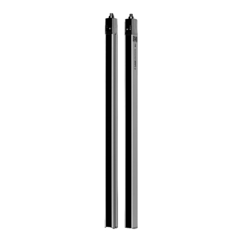
SOLID-2 Safety Light Curtains are type 2 Active Opto-electronic Protective Devices,
(AOPDs) in accordance with EN/IEC 61496-1, EN/IEC 61496-2, PL c in accordance with
ISO 13849-1, designed to Safety Integrated Level 1 (SIL 1) as per EN IEC 61508.
All SOLID-2 Safety Light Curtains are equipped with integrated cyclical testing and
display elements (LEDs and 7-segment display). This is especially convenient when
placing a unit in service or performing diagnostics.
The SOLID-2 is equipped with 2 OSSDs (transistor outputs) with M12 connectors as
standard features.
In addition to the features of the Standard version, the Extended version also offers a
selectable start/restart interlock and contactor monitoring feature.
To provide the best possible solutions for specific applications, SOLID-2 series devices
are available in various resolutions and protective field heights.
1.1 Certifications
Company
Leuze electronic GmbH & Co. KG in D-73277 Owen - Teck, Germany, has a certified
quality assurance system in compliance with ISO 9001.
Products
SOLID-2 Safety Light Curtains are developed and manufactured in compliance with
applicable European directives and international standards.
EC prototype testing in accordance with
EN IEC 61496 Part 1 and Part 2
TÜV PRODUCT SERVICE GmbH, IQSE
Ridlerstrasse 65
D-80339 Munich

General
6 SOLID-2 Leuze electronic
Review-Stand, , 8. April 2015
DEUTSCH ENGLISH FRANÇAIS ITALIANO ESPAÑOL NEDERLANDS
1.2 Symbols and terms
Symbols used:
Warning notice. This symbol indicates possible dangers.
Please pay especially close attention to these instructions!
A note, which also refers to a course of action, provides information
about special attributes or describes set-up procedures
Notice on important information
Symbols of the Transmitter SD2T
General transmitter symbol
Transmitter not active
Transmitter active
Symbols for Receiver SD2R
General receiver symbol
The receiver’s active protective field is not free. Outputs in OFF state
The receiver’s active protective field is free. Outputs in ON state
The receiver’s active protective field is free. Outputs in OFF state
Signal output
Signal input
Signal input and/or output
Table 1.2-1: Symbols

General
Leuze electronic SOLID-2 7
TNT 35/7-24V
Review-Stand, , 8. April 2015
DEUTSCHENGLISHFRANÇAISITALIANOESPAÑOLNEDERLANDS
Terms used in this manual:
AOPD Active Opto-electronic Protective Device
AutoReset After an error indication, for example because of a faulty
external wiring, the AOPD attempts to start again. If the
error is no longer present, the AOPD returns to normal state.
Contactor monitoring
(EDM)
Also called External Device Monitoring (EDM), monitors
dynamically the positive-guided normally closed contacts of
downstream relays, contactors or valves
OSSD1, OSSD2 Safety-related switch output
Output Signal Switching Device
RES Start/REStart interlock
Response time of AOPD The time lag between penetration into the active protective field
of the AOPD and the actual switching off of the OSSDs
Scan All beams, beginning with the synchronization beam, are
pulsed by the transmitter in cycles one after the other
Start/restart interlock
(RES)
Prevents automatic start after the supply voltage has been
turned on, or after the protective field has been penetrated
TC1 Transmission channel 1
TC2 Transmission channel 2
Table 1.2-2: Terms

General
8 SOLID-2 Leuze electronic
Review-Stand, , 8. April 2015
DEUTSCH ENGLISH FRANÇAIS ITALIANO ESPAÑOL NEDERLANDS
1.3 Selecting a SOLID-2
1.3.1 SOLID-2 Safety Light Curtains
Fig. 1.3-1: Selecting a SOLID-2 Safety Light Curtain
SD2trr-xxxx v*
SOLID-2
t- Type of device
T: Transmitter
R: Receiver
r- Resolution
20: 20 mm
30: 30 mm
40: 40 mm
90: 90 mm
xxxx- Protective field height
150 ..... 1800 mm (for 20, 30 and 40 mm resolution)
600..... 3000 mm (for 90 mm resolution)
v- Function version
E: Extended version (with selectable start/restart
interlock and contactor monitoring)
Standard version (automatic start/restart without
contactor monitoring)
*) In the Standard version this place in the product
designation is not used

Safety
Leuze electronic SOLID-2 9
TNT 35/7-24V
Review-Stand, , 8. April 2015
DEUTSCHENGLISHFRANÇAISITALIANOESPAÑOLNEDERLANDS
2Safety
Before using the safety sensor, a risk evaluation must be performed according to valid
standards (e.g. EN ISO 14121, EN ISO 12100-1, ISO 13849-1, IEC 61508, EN 62061). The
result of the risk assessment determines the required safety level of the safety sensor (see
Table 2.1-1). For mounting, operating and testing, document "SOLID-2 Safety Light
Curtain" as well as all applicable national and international standards, regulations, rules
and directives must be observed. Relevant and supplied documents must be observed,
printed out and handed to the affected personnel.
Before working with the safety sensor, completely read and understand the documents
applicable to your task.
In particular, the following national and international legal regulations apply for the start-
up, technical inspections and work with safety sensors:
• Machinery directive 2006/42/EC
• Low voltage directive 2006/95/EC
• Electromagnetic compatibility directive 2004/108/EC
• Use of Work Equipment Directive 89/655/EEC supplemented by Directive 95/63 EC
• OSHA 1910 Subpart 0
• Safety regulations
• Accident-prevention regulations and safety rules
• Ordinance on Industrial Safety and Health and Labor Protection Act
• Device Safety Act
Notice!
For safety-related information you may also contact the local authorities (e.g., industrial
inspectorate, employer's liability insurance association, labor inspectorate, occupational
safety and health authority).
2.1 Approved purpose and foreseeable improper operation
Warning!
A running machine can cause severe injuries!
Make certain that, during all conversions, maintenance work and inspections, the system is
securely shut down and protected against being restarted again.
2.1.1 Proper use
The safety sensor must only be used after it has been selected in accordance with the
respectively applicable instructions and relevant standards, rules and regulations regard-
ing labor protection and occupational safety, and after it has been installed on the
machine, connected, commissioned, and checked by a competent person.
When selecting the safety sensor it must be ensured that its safety-related capability
meets or exceeds the required performance level PLrascertained in the risk assessment.

Safety
10 SOLID-2 Leuze electronic
Review-Stand, , 8. April 2015
DEUTSCH ENGLISH FRANÇAIS ITALIANO ESPAÑOL NEDERLANDS
The following table shows the safety-related characteristic parameters of the SOLID-2
Safety Light Curtain.
Table 2.1-1: Safety-related characteristic parameters of the SOLID-2 Safety Light
Curtain
• The safety sensor protects persons at access points or at points of operation of
machines and plants.
• The safety sensor with vertical mounting detects the penetration by fingers and hands
at points of operation or by the body at access points.
• The safety sensor only detects persons upon entry to the danger zone; it does not
detect persons who are located within the danger zone. For this reason, a start/restart
interlock is mandatory.
• The safety sensor with horizontal mounting detects persons who are located within the
danger zone (presence detection).
• The construction of the safety sensor must not be altered. When manipulating the safety
sensor, the protective function is no longer guaranteed. Manipulating the safety sensor
also voids all warranty claims against the manufacturer of the safety sensor.
• The safety sensor must be tested regularly by competent personnel.
• The safety sensor must be exchanged after a maximum of 20 years. Repairs or the
exchange of parts subject to wear and tear do not extend the service life.
2.1.2 Foreseeable misuse
In principle, the safety sensor is not suitable as a protective device in case of:
• danger of objects being expelled or hot or dangerous liquids spurting from the danger
zone
• applications in explosive or easily flammable atmospheres
Type in accordance with IEC/EN 61496 Type 2
SIL in accordance with IEC 61508 SIL 1
SILCL in accordance with IEC/EN 62061 SILCL 1
Performance Level (PL) in accordance with ISO 13849-1: 2008 PL c
Category in accordance with ISO 13849 Cat. 2
Average probability of a failure to danger per hour (PFHd)
For protective field heights up to 900 mm, all resolutions
For protective field heights up to 1800 mm, all resolutions
For protective field heights up to 2850 mm, all resolutions
8.2 x 10⁻⁸ 1/h
8.9 x 10⁻⁸ 1/h
On request
Service life (TM)20 years

Safety
Leuze electronic SOLID-2 11
TNT 35/7-24V
Review-Stand, , 8. April 2015
DEUTSCHENGLISHFRANÇAISITALIANOESPAÑOLNEDERLANDS
2.2 Competent personnel
Prerequisites for competent personnel:
• he has a suitable technical education
• he knows the rules and regulations for occupational safety, safety at work and safety
technology and can assess the safety of the machine
• he knows the instructions for the safety sensor and the machine
• he has been instructed by the responsible person on the mounting and operation of the
machine and of the safety sensor
2.3 Responsibility for safety
Manufacturer and operating company must ensure that the machine and implemented
safety sensor function properly and that all affected persons are adequately informed and
trained.
The type and content of all imparted information must not lead to unsafe actions by users.
The manufacturer of the machine is responsible for:
• safe machine construction
• safe implementation of the safety sensor
• imparting all relevant information to the operating company
• adhering to all regulations and directives for the safe starting-up of the machine
The company operating the machine is responsible for:
• instructing the operating personnel
• maintaining the safe operation of the machine
• adhering to all regulations and directives for occupational safety and safety at work
• regular testing by competent personnel
2.4 Exemption of liability
Leuze electronic GmbH + Co. KG is not liable in the following cases:
• safety sensor is not used as intended
• safety notices are not adhered to
• reasonably foreseeable misuse is not taken into account
• mounting and electrical connection are not properly performed
• Proper function is not tested (see Chapter 8)
• changes (e.g., constructional) are made to the safety sensor
2.5 Additional safety instructions for access guarding with SOLID-2
Warning!
SOLID-2 Safety Light Curtains with a resolution of 20, 30 or 40 mm detect hands, arms or
bodies of a person entering the protective field, and therefore, it can be placed closer to the
danger point or points than Safety Light Curtains with a resolution of 90 mm. In this case,

Safety
12 SOLID-2 Leuze electronic
Review-Stand, , 8. April 2015
DEUTSCH ENGLISH FRANÇAIS ITALIANO ESPAÑOL NEDERLANDS
the height of the highest and lowest beam above the reference plane must be selected in
accordance with EN ISO 13857.
Valid for all design types: In case of access guarding applications, the start/restart
interlock function is obligatory due to the fact that only access to the danger zone, but not
the area between the protective field and the danger points is monitored.
The start/restart button for unlocking the device must be mounted in such a way that it
cannot be reached from inside the danger zone and the entire danger zone is fully visible
form its installation position.

System design and selectable functions
Leuze electronic SOLID-2 13
TNT 35/7-24V
Review-Stand, , 8. April 2015
DEUTSCHENGLISHFRANÇAISITALIANOESPAÑOLNEDERLANDS
3 System design and selectable functions
3.1 The opto-electronic protective device
Working principle
SOLID-2 consists of a transmitter and a receiver. Beginning with the first beam (the
synchronizing beam) directly after the display panel, the transmitter pulses beam for
beam in rapid sequence. The synchronization between transmitter and receiver is
performed optically.
The receiver recognizes the specially coded pulse packages of the transmitter beams
and opens the corresponding receiver elements in sequence in the same rhythm. A
protective field is consequently formed in the area between transmitter and receiver.
Its height depends on the geometrical dimensions of the protective device and its width is
determined by the distance selected between the transmitter and receiver within the
permissible detection range.
Functions such as start/restart interlock or contactor monitoring can optionally be
performed by the Receiver Extended version.
3.2 Functions of the Transmitter
3.2.1 Transmission channel
The infrared beams are modulated with specially coded pulse packages so that the are
distinct from ambient light, thus ensuring undisturbed operation.
Welding sparks or warning flash lights from passing forklifts do not having any effect on
the protective field.
If two protective fields are located directly next to each other for two adjacent machines,
however, measures must be taken to ensure the optical protective devices do not affect
each other.
Both transmitters should first be assembled “back to back“ so that the beams radiate in
opposite directions. This prevents one system from affecting the other.
a=Transmitter
b=Receiver
Fig. 3.1-1: Working principle of the opto-electronic protective device
a
b

System design and selectable functions
14 SOLID-2 Leuze electronic
Review-Stand, , 8. April 2015
DEUTSCH ENGLISH FRANÇAIS ITALIANO ESPAÑOL NEDERLANDS
Another possible way to suppress mutual influence is to switch one of the two protective
devices from transmission channel 1 to 2 and thus to differently formed pulse packages.
This solution should be considered when more than two optical safety systems must be
arranged next to each other.
Both the transmitter and the receiver of the optical protective system in question must be
switched from transmission channel 1 to 2. For additional information, see Chapter 6.
3.2.2 Internal or external testing
If external testing is desired, the test input of the transmitter must be wired in accordance
with the connection and operating instructions of the selected testing safety interface. The
testing safety interface will turn the transmitter off and back on, verifying that the selected
single OSSD of the receiver is turned off and on in accordance. For more details, see
Chapter 6.1.1.2.
In most cases, however, internal cyclical testing is sufficient. For this purpose, the
transmitter‘s test input must be connected with +24V DC. Both OSSDs must be integrated
into the safety circuit as a two-channel system.
3.3 Selectable function of the Receiver Standard and Extended
3.3.1 Transmission channel
If the transmitter is switched to transmission channel 2, the corresponding receiver must
also be set to transmission channel 2. See Chapter 6.
a=AOPD “A“ transmission channel 1
b=AOPD “B“ transmission channel 2, not affected by AOPD “A“
Fig. 3.2-1: Transmission channel selection
a
b

System design and selectable functions
Leuze electronic SOLID-2 15
TNT 35/7-24V
Review-Stand, , 8. April 2015
DEUTSCHENGLISHFRANÇAISITALIANOESPAÑOLNEDERLANDS
3.4 Additional functions of the Receiver Extended
3.4.1 Start/restart interlock (RES)
If the start/restart interlock function is activated, it prevents the safety circuits from being
released automatically when the machine is turned on or the power supply is switched on
or is restored after a power outage. The receiver only switches to the ON state by pressing
and releasing the start/resart button within a time window.
If the protective field is interrupted, the start/restart interlock function ensures that the
receiver will remain in the OFF state after the protective field is released again. The
receiver will then not be switched back to the ON state until the start/restart button is
pressed and released again.
Activate the start/restart interlock:
✟with the circuitry in the Receiver Extended (see Chapter 6.1.3)
✟or in the downstream machine control unit
✟or in the downstream safety PLC
Once the internal start/restart interlock is activated as described in Chapter 6.1.3, this
function is monitored dynamically. The receiver cannot be switched back to the ON state
until the start/restart button is pressed and released again within a time window of 300 ms
to 5 s, with the protective field free.
Fig. 3.4-1: Start/restart interlock function in effect when the supply voltage is turned
on
Fig. 3.4-2: The start/restart interlock function after the protective field has been
penetrated

System design and selectable functions
16 SOLID-2 Leuze electronic
Review-Stand, , 8. April 2015
DEUTSCH ENGLISH FRANÇAIS ITALIANO ESPAÑOL NEDERLANDS
3.4.2 Contactor monitoring (EDM)
If the “Contactor monitoring” function is activated, it dynamically monitors contactors,
relays or valves downstream from the SOLID-2. Precondition here are switching elements
with positive-guided feedback contacts (normally closed).
You can implement the contactor monitoring function with:
✟The internal contactor monitoring in the Receiver Extended (see Chapter 6.1.3)
✟or via a downstream safety PLC
If the internal contactor monitoring function is activated, it works dynamically, i.e. in
addition to verifying that the feedback loop is closed before turning on the OSSDs the
system checks whether the feedback circuit has opened within 500 ms of being enabled
and whether it has closed again within 500 ms when turning off the OSSDs. If this is not
the case, the OSSDs will assume an OFF state again shortly after turning on. A error
message appears at the 7-segment display, E 30.
Fig. 3.4-3: Contact monitoring function, combined in this example with a start/
restart interlock

Display elements
Leuze electronic SOLID-2 17
TNT 35/7-24V
Review-Stand, , 8. April 2015
DEUTSCHENGLISHFRANÇAISITALIANOESPAÑOLNEDERLANDS
4 Display elements
4.1 Transmitter status displays
When the transmitter’s green LED1 is lit, this indicates that the supply voltage is available.
Display of the current state of the transmitter:
a = LED1 (green/red)
b = LED2 (green/red)
Fig. 4.1-1: Transmitter, LED status displays
Indication Meaning
LED1 green LED2 off Supply voltage present, TC1 selected
LED1 green LED2 green Supply voltage present, TC2 selected
LED1 green LED2 red Supply voltage present, TC1 or TC2 selected, external
test signal activated
LED1 red LED2 any state Device fault
Table 4.1-1: Transmitter, LED status displays
ab

Display elements
18 SOLID-2 Leuze electronic
Review-Stand, , 8. April 2015
DEUTSCH ENGLISH FRANÇAIS ITALIANO ESPAÑOL NEDERLANDS
4.2 Receiver status displays
LED1 and the 7-segment display report on the operating states of the Receiver Standard.
LED2 is added in case of Receiver Extended.
4.2.1 7-segment display
After the electrical supply voltage is turned on, the following data appear on the receiver’s
7- segment display:
a=Symbol for OSSDs
b=LED1 = red/green
c=Symbol for interlocking state
d=LED2 = yellow
Fig. 4.2-1: Receiver, status displays
7-segment
display
Meaning
Permanent display after startup
1 or 2 Indication of transmission channel TC1 or TC2
Table 4.2-1: Receiver, 7-segment permanent displays
7-segment
display
Meaning
Temporary event displays, 1 s per display
E xx Locking status display “error“, which can be eliminated by the user
E xx = Error code (for example contactor monitoring error E 30, see Chap-
ter 9). The display shows repeating the sequence of E, 3 (1st position)
and 0 (2nd position).
F xx Locking status display „device fault“ and an internal fault code.
Receiver must be replaced.
1 or 2
flashing
Flashing transmission channel number → weak signal display, device not
adjusted optimally or contaminated front screens
Table 4.2-2: Receiver, 7-segment temporary event display
bd
c
a

Display elements
Leuze electronic SOLID-2 19
TNT 35/7-24V
Review-Stand, , 8. April 2015
DEUTSCHENGLISHFRANÇAISITALIANOESPAÑOLNEDERLANDS
4.2.2 LED displays
4.2.2.1 Receiver Standard, LED status displays
4.2.2.2 Receiver Extended, LED status displays
If the internal start/restart function is not activated, the Receiver Extended indicates only
the status of the OSSDs safety outputs in the same way like the Receiver Standard,
described under 4.2.2.1.
The following table is valid, if the internal start/restart function is activated.
LED Color Meaning
LED1 red/
green
red =OSSDs safety outputs in the OFF state
green =OSSDs safety outputs in the ON state
No display =Device without supply voltage
Table 4.2-3: Receiver Standard, LED status displays
LED Color Meaning
LED1 red/
green
red =OSSDs safety outputs in the OFF state
green =OSSDs safety outputs in the ON state
No display =No supply voltage to the device
LED2 yellow ON =Internal start/restart interlock activated; The OSSDs
safety outputs are switched to the OFF state. If the
protective field is free,
the device can be unlocked by pressing and
releasing the start/restart button in a time window of
300 ms to 5 s.
OFF =If the OSSDs are in ON state (LED1 green):
Internal start/restart interlock function is not activa-
ted.
If OSSDs are in OFF state (LED1 red):
Internal start/restart function is activated and the
protective field is not free.
Table 4.2-4: Receiver Extended, LED status displays when start/restart interlock
function is activated

Display elements
20 SOLID-2 Leuze electronic
Review-Stand, , 8. April 2015
DEUTSCH ENGLISH FRANÇAIS ITALIANO ESPAÑOL NEDERLANDS
4.2.2.3 Receiver Extended, LED displays and protective field states when the internal
start/restart interlock function is activated:
The following illustrations show the behaviour of the LEDs and OSSDs in start/restart
interlock operating mode.
LED1 LED2 Protective
field
Meaning
green OFF free LED1
green
=OSSDs safety outputs in the ON state
LED2 OFF =Start/restart interlock not active, see Fig.
4.2-2 a
red OFF interrupted LED1 red =OSSDs safety outputs in the OFF state
LED2 OFF =Start/restart interlock not active.
As long as the protective field is interrup-
ted, it is not possible to start/restart the de-
vice, see Fig. 4.2-2 b
red yellow free LED1 red =OSSDs safety outputs in the OFF state
LED2
yellow
=Start/restart interlock active. The OSSDs
safety outputs are only turned on again af-
ter pressing and releasing the start/restart
button in a time window of 300 ms to 5 s,
see Fig. 4.2-2 c-e
Table 4.2-5: Receiver Extended with selected internal start/restart interlock function
a b c d e
LED1: green
LED2: OFF
OSSDs: ON
LED1: red
LED2: OFF
OSSDs: OFF
LED1: red
LED2: yellow
OSSDs: OFF
LED1: green
LED2: OFF
OSSDs: ON
Fig. 4.2-2: Start/restart interlock function after intrusion into the protective field
This manual suits for next models
8
Table of contents
Other Leuze electronic Security Sensor manuals

Leuze electronic
Leuze electronic MLC 520 User manual

Leuze electronic
Leuze electronic CRT448 User manual

Leuze electronic
Leuze electronic MLD 300 User manual

Leuze electronic
Leuze electronic MLC 300 Series User manual

Leuze electronic
Leuze electronic OPSL 775 User manual

Leuze electronic
Leuze electronic MLC 500 Series User manual

Leuze electronic
Leuze electronic OPSL 775 User manual

Leuze electronic
Leuze electronic CML 720i Ex User manual

Leuze electronic
Leuze electronic RSL 430 User manual

Leuze electronic
Leuze electronic MLC 500 User manual