Leviton Decora DZR15 User manual

Preparing and connecting wires:
This receptacle can be wired using side wire terminal screws or
through backwire openings. Choose appropriate wire stripping
specifications accordingly.
WARNING: TO AVOID FIRE SHOCK OR DEATH; TURN
OFF POWER at circuit breaker or fuse and test that power is off
before wiring!
Identifying your wiring application (most common):
NOTE: If the wiring in your wall box does not resemble any of
these configurations, consult a qualified electrician.
WARNINGS AND CAUTIONS:
•
TO AVOID FIRE SHOCK OR DEATH; TURN OFF POWER at circuit breaker or fuse and test that power is off before wiring!
• To be installed and/or used in accordance with electrical codes and regulations.
• If you are unsure about any part of these instructions, consult an electrician.
• To ensure that there is adequate room for wires, we recommend using at a minimum 3-1/2 inch deep wallboxes. For single-gang applications, this would be at a
minimum an 18-cubic inch wallbox.
WARNINGS AND CAUTIONS:
• Disconnect power at circuit breaker or fuse when servicing, installing or removing fixture.
• Maximum wire length cannot exceed 300 ft (90 m).
• Use this device with copper or copper clad wire only.
• Not for use with Vizia RF
®
lighting systems.
Duplex Receptacle (Top Controlled)
Scene Capable Receptacle
Cat. No. DZR15 - 15A - 125VAC, 60Hz
Incandescent-1800W – Magnetic Low-Voltage-1800VA (1440W)
Electronic Low-Voltage-1800W – Fluorescent-1800VA – Supplemental-1/2 HP
INSTALLATION INSTRUCTIONS
DI-000-DZR15-02A
TOOLS NEEDED TO INSTALL YOUR RECEPTACLE
Slotted/Phillips Screwdriver Electrical Tape Pliers
Pencil Cutters Ruler
Changing the color of your Receptacle:
Your Receptacle includes three color options. The Receptacle ships with the
White frame attached. To change color of frame, proceed as follows:
INSTALLING YOUR RECEPTACLE
NOTE: Use check boxes when Steps are completed.
/./&&
/./&&
/./&&
/./&&
/./&&
/./&&
/./&&/./&&
/./&&
/./&&
/./&&
/./&&
Step 1
2
4
3
1
Single Pole
1. Line (Hot)
2. Neutral
3. Ground
Step 2
Single Pole Wiring Application:
Step 3
• Make sure that the ends of the wires from the wall box are
straight (cut if necessary).
• Remove insulation from each wire in the wall box as shown.
5/8"
(1.6 cm) Strip Gage
(measure bare
wire here)
Cut
(if necessary)
Side Wire Connection
Side wire terminals accept #14-12
AWG solid copper wire only.
Back Wire (either hole may be used)
Back wire openings accept #14-12
AWG solid copper wire only.
WIRING RECEPTACLE:
Connect wires per WIRING DIAGRAM as follows:
• Green or bare copper wire in wall box to Green terminal screw.
• Line Hot wall box wire to terminal screw marked "LINE".
• Line Neutral wall box wire to terminal screw marked "NEUTRAL".
• Proceed to Step 5.
Leviton’s Decora
®
Z-Wave
®
control components are designed to
communicate with each other via Radio Frequency (RF) to provide remote
control of your lighting. In a Z-Wave
®
network, each device is designed
to act as a router. These routers will re-transmit the RF signal from one
device to another until the intended device is reached. This ensures
that the signal is received by its intended device by routing the signal
around obstacles and radio dead spots. The Scene Capable Electronic
Receptacle is compatible with most Z-Wave
®
enabled networks, from
different manufacturers and can also be used with other devices displaying
the Z-Wave
®
logo.
WARNING:
TO AVOID FIRE, PERSONAL INJURY OR DEATH DO NOT
USE the remote for the control of high power heating appliances such
as portable heaters.
Remember to exercise good common sense when
using the Timer features of your Remote – especially when scheduling
unattended devices. There can be some unexpected consequences if
not used with care. For example, an empty coffee pot can be remotely
turned on. If that should happen, your coffee pot could be damaged from
overheating. If an electric heater is turned on by remote control while
clothing is draped over it, a fire could result. DO NOT USE the remote for
the control of high power heating appliances such as portable heaters.
• Receptacle ON/OFF
• Scene Capable
• ON/OFF LED
• Two way communication
• RF reliability
• Ease of installation – No new wiring
• Compatible with other Z-Wave®enabled devices
FEATURES
INTRODUCTION Testing your Receptacle prior to mounting in
wall box:
Receptacle Mounting:
TURN OFF POWER AT CIRCUIT BREAKER OR FUSE.
• Restore power at circuit breaker or fuse.
• Locator light should turn ON.
If locator light does not turn ON, refer to the TROUBLESHOOTING
section.
Step 5
• Position all wires to provide room in outlet wall box for device.
• Partially screw in mounting screws in wall box mounting holes.
NOTE: Dress wires with a bend as shown in diagram in order to
relieve stress when mounting device.
Step 6
Restore Power:
Restore power at circuit breaker or fuse.
Installation is complete.
Step 7
Neutral (Silver) Line (Black)
Green
Ground
CONTROLLED
Push in side
at tab to release
Line up tabs and
press in sides one at a time
to attach
Step 4
CONTROLLED
Installation may now be completed by tightening
mounting screws into wall box. Attach wallplate.
NOTE: To include your dimmer into a network, contact
Leviton’s Techline at 1-800-824-3005 or visit Leviton’s
website at www.leviton.com.
WEB VERSION

DI-000-DZR15-02A
For additional information, contact Leviton’s
Techline at 1-800-824-3005 or visit Leviton’s
website at www.leviton.com
Covered by U.S. Pat. Nos.: 7,756,556; 7,938,676; 8,105,094 and
corresponding foreign equivalents.
Licensed under U.S. Pat. Nos. 5,905,442, and 5,982,103
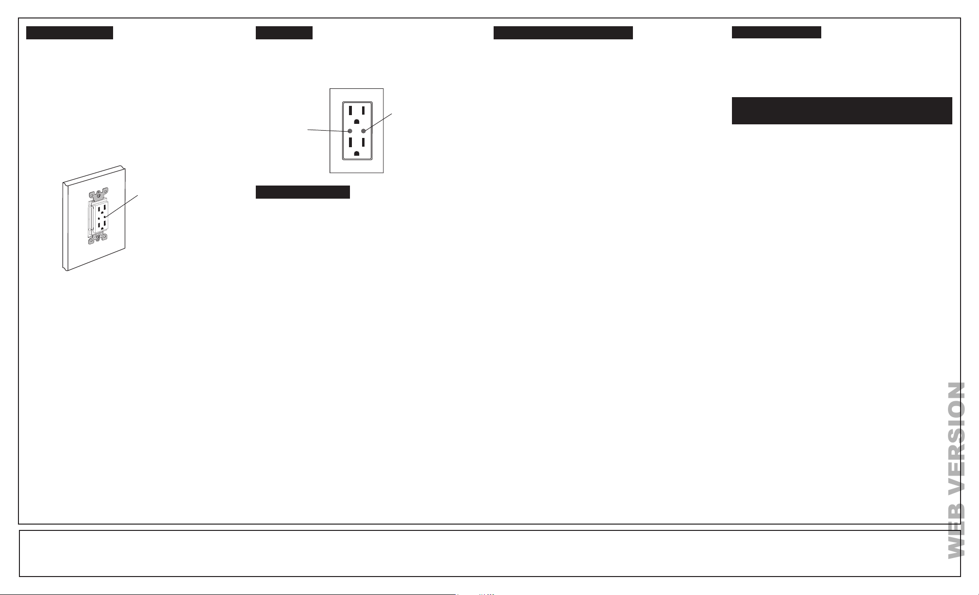
CONTROLLED
Programming
button
Locator
Light
NOTE: The locator light will illuminate when receptacle is connected.
If there is a power outage, when the power is restored, the lights will return
to the last setting before the power interruption.
Cleaning: Clean with a damp cloth. DO NOT use chemical cleaners.
OPERATION
TROUBLESHOOTING
• Receptacle has no power
- Receptacle has a bad connection.
- Wires not secured firmly under terminal screws of receptacle.
• Locator LED does not turn ON
- Circuit breaker or fuse has tripped.
- Neutral connection is not wired.
- Press progarmming button.
If your receptacle is not responding, or you are unable to control it after
you have tried to Include/Exclude it multiple times, it may be necessary
to reset the receptacle to its original factory settings. To accomplish this,
proceed as follows:
• On the receptacle, press and hold the program button until the locator
LED turns Amber and then flashes Red. The receptacle is now reset.
Once the receptacle is reset, it will be necessary to Re-Include it to a
network before it can be used.
CAUTION: SETTING A DEVICE TO A FACTORY DEFAULT DOES
NOT EXCLUDE THAT DEVICE FROM A NETWORK. THE EXCLUSION
PROCEDURE MUST STILL BE FOLLOWED TO REMOVE THE DEVICE
FROM THE PRIMARY CONTROLLER’S INFORMATION TABLE.
FAILURE TO DO SO MAY RESULT IN SYSTEM THAT IS SLOW TO
RESPOND, OR MAY FAIL TO RESPOND TO SOME DEVICES.
Gently press
Programming button
© 2014 Leviton Mfg. Co., Inc.
FOR CANADA ONLY
For warranty information and/or product returns, residents of Canada
should contact Leviton in writing at Leviton Manufacturing of Canada
Ltd to the attention of the Quality Assurance Department, 165
Hymus Blvd, Pointe-Claire (Quebec), Canada H9R 1E9 or by
telephone at 1-800-405-5320.
Z-Wave is a registered trademark of Sigma Designs Inc
and/or its subsidiaries
FACTORYDEFAULT
This device complies with Part 15 of the FCC Rules. Operation is subject to
following two conditions: (1) this device may not cause harmful interference, and
(2) this device must accept any interference received, including interference that
may cause undesired operation of the device.
This equipment has been tested and found to comply with the limits for a
Class B Digital Device, pursuant to Part 15 of the FCC Rules. These limits
are designed to provide reasonable protection against harmful interference
in a residential installation. This equipment generates, uses, and can radiate
radio frequency energy and, if not installed and used in accordance with the
instructions, may cause harmful interference to radio communications. However,
there is no guarantee that interference will not occur in a particular installation. If
this equipment does cause harmful interference to radio or television reception,
which can be determined by turning the equipment OFF and ON, the user is
encouraged to try to correct the interference by one or more of the following
measures:
• Reorient or relocate the receiving Antenna.
• Increase the separation between the equipment and the receiver.
• Connect the equipment into an outlet on a circuit different from that to which
the receiver is connected.
• Consult the dealer or an experienced radio/tv technician for help.
FCC CAUTION
Any changes or modifications not expressly approved by Leviton Manufacturing
Co., Inc., could void the user's authority to operate the equipment.
FCC COMPLIANCE STATEMENT
LIMITED 5 YEAR WARRANTY AND EXCLUSIONS
Leviton warrants to the original consumer purchaser and not for the benefit of anyone else that this product at the time of its sale by Leviton is free of defects in materials and workmanship under normal and proper use for five years from the purchase date. Leviton’s only obligation is to correct
such defects by repair or replacement, at its option. For details visit www.leviton.com or call 1-800-824-3005. This warranty excludes and there is disclaimed liability for labor for removal of this product or reinstallation. This warranty is void if this product is installed improperly or in an
improper environment, overloaded, misused, opened, abused, or altered in any manner, or is not used under normal operating conditions or not in accordance with any labels or instructions. There are no other or implied warranties of any kind, including merchantability and fitness for
a particular purpose, but if any implied warranty is required by the applicable jurisdiction, the duration of any such implied warranty, including merchantability and fitness for a particular purpose, is limited to five years. Leviton is not liable for incidental, indirect, special, or consequential
damages, including without limitation, damage to, or loss of use of, any equipment, lost sales or profits or delay or failure to perform this warranty obligation. The remedies provided herein are the exclusive remedies under this warranty, whether based on contract, tort or otherwise.
WEB VERSION
Other Leviton Control System manuals

Leviton
Leviton 48211-AVC User manual

Leviton
Leviton DOS05 User manual

Leviton
Leviton Dimensions D3200 User guide

Leviton
Leviton D4200 User manual

Leviton
Leviton 600 Series User manual

Leviton
Leviton DMX-512 User manual

Leviton
Leviton Lumina LU20S-DNW User manual

Leviton
Leviton DOS05 User manual

Leviton
Leviton 4106 User manual
Popular Control System manuals by other brands

Dahua Technology
Dahua Technology DHI-IPMECD-3021 Series user manual

Johnson Controls
Johnson Controls CMS-1655 installation guide

Crestron
Crestron MPC-M50 Operations & installation guide

ComfortNET
ComfortNET CTK02AA Homeowner's guide

Carrier
Carrier AQUASNAP 30RA/RH Operation & maintenance instructions

Ansul
Ansul AUTOPULSE IQ-636X-2/E installation manual