manuals.online logo
Brands
  1. Home
  2. •
  3. Brands
  4. •
  5. Leviton
  6. •
  7. Relay
  8. •
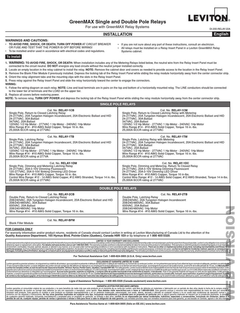
  9. Leviton GreenMAX R16TC-100 User manual

Leviton GreenMAX R16TC-100 User manual

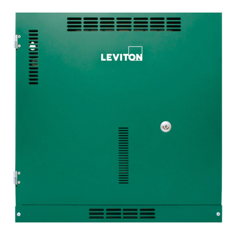
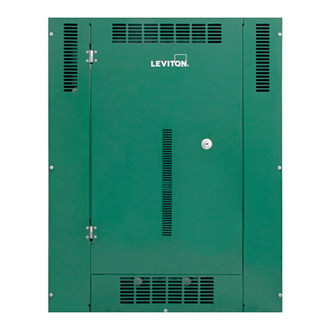
GreenMAX Relay System Cabinet
Cat. Nos. R16TC-100, R32TC-100, R48TC-100
For use with GreenMAX Relay Systems
WARNINGS AND CAUTIONS:
• To be installed and/or used in accordance with electrical codes and regulations.
• Installation and maintenance of this unit and the associated components requires an electrician.
• All relays must be installed on a Relay Insert Panel in a Leviton GreenMAX Relay Systems cabinet.
• The covers and lower ventilation plate must be in place when any circuit in the cabinet is energized.
• Arelayorllermodulemustbeinstalledineveryrelaylocationwhenanycircuitinthecabinetis
energized.
INSTALLATION English
PK-93838-10-00-0B
To Install
MOUNT CABINET
1. WARNING: TO AVOID FIRE, SHOCK, OR DEATH; TURN OFF POWER AT CIRCUIT BREAKER OR FUSE AND
TEST THAT THE POWER IS OFF BEFORE WIRING!
2. Securely mount enclosure to wall using fasteners appropriate for wall type.
NOTE: Mounting holes are provided in the enclosure, the upper holes are keyhole slots to facilitate easy
hanging.Anyelddrilledmountingholesshouldbeconnedtothewire-wayareassothattheydonotobstruct
the installation of the Relay Insert Panels or the Command Module.
3. Install all conduit runs and pull all lighting circuit and power wiring.
NOTE: It is recommended that all wire be pulled prior to installing the Command Module and Relay Insert
Panels. This will prevent damage to the electrical components.
INSTALL COMMAND MODULE
1. Install the Command Module by sliding the slots on the bottom of the Command Module over the mounting tabs
of the cabinet. Pass the Power Supply leads through the grommet to the power wiring area while installing. The
Command Module should be free to rotate forward and back without any obstruction. Fasten the Command
Module in place with the two screws provided (see Detail on page 2).
2. Connect the incoming Line, Neutral, and Ground wires of the designated power circuit, to the cabinet electronics.
NOTE: This connection should be made in the power wiring area provided. If the source of power requires that
this area must be separated from other circuit conductors, install the metal partitions provided. The Neutral
connection must also include the Neutral wire from the uppermost Relay Insert Panel. A jumper is provided to
extend this conductor from the Relay distribution spine to the connection point.
3. Connect the Equipment Grounding conductor to the grounding location provided adjacent to the system power
supply. Use the ground screw provided for this purpose.
4. Using Cat 5 (or better) cables and RJ45 connectors, connect the Power Supply to both the MPU and the Low
Voltage input board using the designated ports.
NOTE: If Low Voltage inputs are required, make these connections according to the diagrams provided for the
specicinputtype.Toaidthisprocess,removetheterminalblocksbypullingthegreenblockstraightoutand
away from the module. Provide enough cable length to allow the unobstructed movement of the Command
Module.
INSTALL RELAY INSERT PANEL
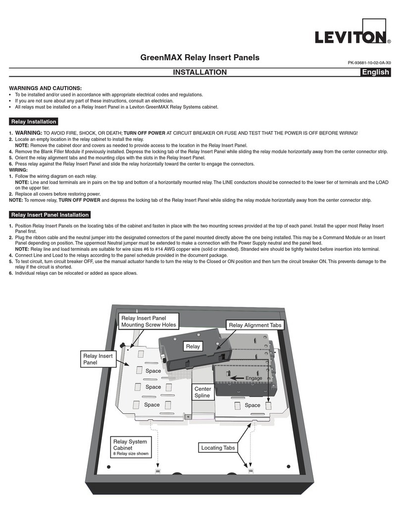
1. Position Relay Insert Panel on the locating tabs of the cabinet and fasten in place with the two mounting screws
provided at the top of the panel. Plug the ribbon cable into the Command Module. The Neutral jumper must be
extendedtomakeaconnectionwiththePowerSupplyneutralandthepanelfeed.Installrelaysorllermodules
in all locations.
2. Connect Line and Load to the relays according to the panel schedule provided in the document package.
NOTE: Relay line and load terminals are suitable for wire sizes #10 to #14 AWG Copper.
WIRE LOW VOLTAGE INPUT CARD
1. Wire Low Voltage wiring according to the device wiring diagrams.
NOTE: LowVoltagewiringshouldbeconnedtothedesignatedareasatthetopoftheenclosure.LumaCAN
wiringisinterconnectedwithCat5(orbetter)cableandRJ45connectors.Allcablesshouldbetestedandveried
for proper operation before being connected to any components.
NOTE: The area at the top left corner of the enclosure can be used for either Low Voltage or High Voltage wiring.
A metal barrier is provided to segregate Lighting/ Power Wiring and Low Voltage wiring. The barrier can be
relocated as necessary.
NOTE: Low voltage wire should be #14 - #24 AWG.
RATINGS:
• Forrelayratings,seetheInstallationSheetprovidedwitheithertheRelayInsertPanelsortheIndividualrelay.
•The power requirement of the Command Module is: 100-277VAC 50/60Hz
• TheloadratingofthePowerSupplyoftheCommandModuleis:70W@24VDC+/-10%
• ThiscomponentissuitableforNEMA1applicationsonly(indooruse/notwaterorweatherresistant).
3. To test circuit, turn circuit breaker OFF, use the manual actuator handle to turn the relay to the Closed or ON
position and then turn circuit Breaker ON. This prevents damage to the relay if the circuit is shorted.
NOTE: Individual relays can be relocated or added by aligning and inserting tabs on the base of the relay in the
slots provided in the back-plate. While inserted, slide the relay toward the center until completely engaged.
Relay Insert Panels
Cat Number:
R1600-000 R1616-1DS
R1616-1CB R1616-2CB
R1616-1CS R1616-2CS
R1616-1TB R1616-2TB (SHOWN)
R1616-1TS R1616-2TS
Enclosure
Cat Number:
R16TC-100
R32TC-100
R48TC-100 (SHOWN)
Multi-use Areas
Removable
barriers partition
this area to
meeteld
requirements.
Mounting holes
Quantity of
holes provided
depends on
length of cabinet.
Upper holes are
slotted to ease
installation.
Additonal holes
may be added
in the wireway
area only. Avoid
areas reserved
for the Relay
Insert Panels and
the Command
Module.
Conduit Entry
Conduits can
enter the cabinet
on all four (4)
sides. Plan for
Low Voltage
conductors at
the top of the
enclosure.
Low Voltage Area
Relay Insert Panel Mounting Tab
Line Terminals Phase 1
Phase 2
Load Terminals
Manual Actuator
Command Module
Cat Number:
RPM00-100
RPM08-108
RPM16-116 (SHOWN)
Lighting & Power Wireway
Wireway
Hook Detail
Left Cover Enclosure
INSTALL COVERS AND DOORS
NOTE: The Cover and Door assembly consists of four components; lower vent plate, left cover, right cover,
and the door.
NOTE: The covers and lower vent plate must be in place when any circuit in the cabinet is energized.
1. To install the left and right covers, start a mounting screw in the second from the bottom screw hole on the
cabinetange.Donotcompletelytightenscrewbutleaveenoughspaceforthethicknessofthecover.Locate
the upper mounting hook on the cover and the corresponding tab on the enclosure. Locate the keyhole slot at
the second from the bottom location. Align both the hook and the keyhole slot with their mating features of
the cabinet and slide in place. See Hook Detail.
2. Install all mounting screws provided to permanently fasten the covers in place.
3. Install the lower ventilation panel by sliding mating tabs of the left and right covers through the slots provided
in the ventilation plate. Lower the ventilation plate into place and fasten with mounting screws.
4. Install the door by sliding the halves of the hinges together. Hang the door on one hinge pin at a time, the pins
are different lengths to facilitate easy assembly.
LIMITED 10 YEAR WARRANTY AND EXCLUSIONS
LevitonwarrantstotheoriginalconsumerpurchaserandnotforthebenetofanyoneelsethatthisproductatthetimeofitssalebyLevitonisfreeofdefectsinmaterialsandworkmanshipundernormalandproperusefortenyearsfromthepurchasedate.Leviton’sonlyobligationistocorrectsuchdefectsbyrepairor
replacement, at its option, if within such ten year period the product is returned prepaid, with proof of purchase date, and a description of the problem to Leviton Mfg. Co., Inc. 201 North Service Road, Melville, N.Y. 11747, U.S.A. This warranty excludes and there is disclaimed liability for labor for removal of this product
or reinstallation. This warranty is void if this product is installed improperly or in an improper environment, overloaded, misused, opened, abused, or altered in any manner, or is not used under normal operating conditions or not in accordance with any labels or instructions. There are no other or implied warranties of
any kind, including merchantability and tness for a particular purpose,butifanyimpliedwarrantyisrequiredbytheapplicablejurisdiction,thedurationofanysuchimpliedwarranty,includingmerchantabilityandtnessforaparticularpurpose,islimitedtotenyears.Leviton is not liable for incidental, indirect,
special, or consequential damages, including without limitation, damage to, or loss of use of, any equipment, lost sales or prots or delay or failure to perform this warranty obligation. The remedies provided herein are the exclusive remedies under this warranty, whether based on contract, tort or otherwise.
For Technical Assistance Call: 1-800-959-6004 (U.S.A. Only)
www.leviton.com
COMMAND MODULE DETAIL
Power Supply
Ground power
supply here MPU
Feed wires
through hole Mounting Tabs
DIP Switch
Low Voltage
Input Card
16 Inputs shown
LumCan Ports
4 LumCan Ports
DIP Switch
Hinge
32 Relay Cabinet48 Relay Cabinet 16 Relay Cabinet
Lower
Vent
Plate
Keyhole
Slot &
Temporary
Mounting
Screw
Right
Cover
Left
Cover
Lock
Door
DIP SWITCH SETTINGS
Set the ID Address of the Command Module and Low Voltage
Input Card - Examples shown below
ID 1 ID 2 ID 3 ID 4 ID 5 ID 6 ID 38 ID 86
1
2
4
8
16
32
64
128
O N
1 2 3 4 5 6 7 8
O N
1 2 3 4 5 6 7 8
O N
1 2 3 4 5 6 7 8
O N
1 2 3 4 5 6 7 8
O N
1 2 3 4 5 6 7 8
O N
1 2 3 4 5 6 7 8
O N
1 2 3 4 5 6 7 8
O N
1 2 3 4 5 6 7 8
ID Address Value = Sum of Switch Values
ID86=2+4+16+64
Switch
Values
PK-93838-10-00-0B
© 2010 Leviton Mfg. Co., Inc.
64"
48"
31-1/2"
* 10 year warranty on relays. 2 year warranty on all other components

This manual suits for next models

2

Other Leviton Relay manuals

Leviton EZ-Max Plus Operating instructions

Leviton

Leviton EZ-Max Plus Operating instructions

Leviton GreenMAX RELAY-1TB User manual

Leviton

Leviton GreenMAX RELAY-1TB User manual

Leviton EZ-MAX H Series User manual

Leviton

Leviton EZ-MAX H Series User manual

Leviton EZ-MAX Plus 16 User manual

Leviton

Leviton EZ-MAX Plus 16 User manual

Leviton GreenMAX R16TC-100 User manual

Leviton

Leviton GreenMAX R16TC-100 User manual

Leviton WSP05-010 User manual

Leviton

Leviton WSP05-010 User manual

Leviton EnOcean WSPAS-LV4 User manual

Leviton

Leviton EnOcean WSPAS-LV4 User manual

Leviton Z-MAX r24sd User manual

Leviton

Leviton Z-MAX r24sd User manual

Leviton GreenMAX Relay System Cabinet User manual

Leviton

Leviton GreenMAX Relay System Cabinet User manual

Leviton GreenMAX Series User manual

Leviton

Leviton GreenMAX Series User manual

Leviton GreenMAX R1616-1CB User manual

Leviton

Leviton GreenMAX R1616-1CB User manual

Leviton EZ-MAX Plus 8 User manual

Leviton

Leviton EZ-MAX Plus 8 User manual

Leviton EZ-Max Plus Operating instructions

Leviton

Leviton EZ-Max Plus Operating instructions

Leviton Z-Max Remote Installation and operating instructions

Leviton

Leviton Z-Max Remote Installation and operating instructions

Leviton EZ-MAX User manual

Leviton

Leviton EZ-MAX User manual

Leviton 40A00-1 Mounting instructions

Leviton

Leviton 40A00-1 Mounting instructions

Popular Relay manuals by other brands

Schweitzer Engineering Laboratories SEL-251 instruction manual

Schweitzer Engineering Laboratories

Schweitzer Engineering Laboratories SEL-251 instruction manual

ALIND AR39 user manual

ALIND

ALIND AR39 user manual

Panasonic AQ-H Series manual

Panasonic

Panasonic AQ-H Series manual

Siemens SIRIUS 3RA2943-2AA1 Original operating instructions

Siemens

Siemens SIRIUS 3RA2943-2AA1 Original operating instructions

Devantech dS3484 user manual

Devantech

Devantech dS3484 user manual

Deditec MOD-REL8 10A Hardware description

Deditec

Deditec MOD-REL8 10A Hardware description

GMI D5094S-104 instruction manual

GMI

GMI D5094S-104 instruction manual

Siemens SIRIUS 3RF24 AB Series operating instructions

Siemens

Siemens SIRIUS 3RF24 AB Series operating instructions

finder 10.32.8.230 quick start guide

finder

finder 10.32.8.230 quick start guide

Alstom EPAC 3100 Installer's guide

Alstom

Alstom EPAC 3100 Installer's guide

Crouzet GNR Installation sheet

Crouzet

Crouzet GNR Installation sheet

Westinghouse SBF-1 Installation, operation & maintenance instructions

Westinghouse

Westinghouse SBF-1 Installation, operation & maintenance instructions

FANOX SIA-B Installation & commissioning guide

FANOX

FANOX SIA-B Installation & commissioning guide

ISB SR4001 operating instructions

ISB

ISB SR4001 operating instructions

ABB RXHL 422 Connection and Settings Guide

ABB

ABB RXHL 422 Connection and Settings Guide

Schrack LSZ0Y001 operating instructions

Schrack

Schrack LSZ0Y001 operating instructions

Siemens 3RT2840.-2 Original operating instructions

Siemens

Siemens 3RT2840.-2 Original operating instructions

ELBRO SMSB 2 Series quick reference

ELBRO

ELBRO SMSB 2 Series quick reference

manuals.online logo
manuals.online logoBrands
  • About & Mission
  • Contact us
  • Privacy Policy
  • Terms and Conditions

Copyright 2025 Manuals.Online. All Rights Reserved.