WARNINGS AND CAUTIONS:
• DISCONNECT POWER AT CIRCUIT BREAKER OR FUSE WHEN SERVICING, INSTALLING OR REMOVING FIXTURE.
• DO NOTcontrolaloadinexcessofthespeciedratings.Damagetotheunit,re,electricshock,personalinjuryordeathcanoccur.
Checkyourloadratingstodeterminesuitabilityforyourapplication.
• Ifyouareunsureaboutanypartoftheseinstructions,consultanelectrician.
• Tobeinstalledand/orusedinaccordancewithelectricalcodesandregulations.
WARNINGS AND CAUTIONS:
• Donotinstallthisunittocontrolareceptacle.
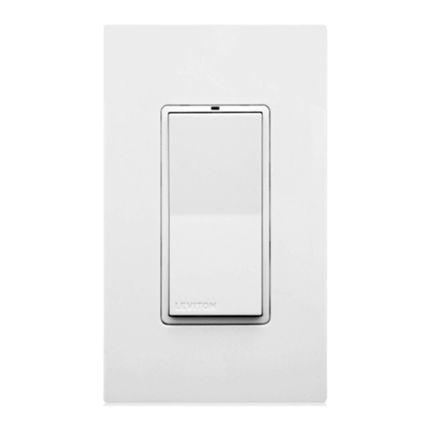
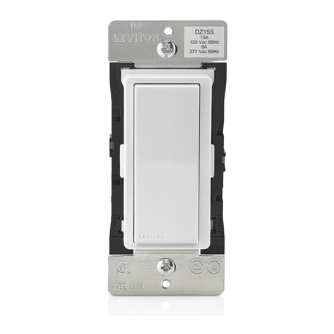
• TheOSSMTVacancySensorisintendedtoreplaceastandardsingle-poleDecorawallswitch.
• Donottouchthesurfaceofthelens.Cleanoutersurfacewithadampclothonly.
• UsethisdeviceWITH COPPER OR COPPER CLAD WIRE ONLY.
SinglePole(OneLocation)orMulti-Location
Multi-Technology Designer Wall Switch Vacancy Sensor
California Title 20 and 24 Compliant
Cat. No. OSSMT-TM & OSSMT-GT
Incandescent/Tungsten:800W@120VBallast:1200VA@120VBallast:2700VA@277VMotor:1/4hp@120V
Operating Temperature Range:0°Cto40°C
Relative Humidity:20%to90%non-condensing
No Minimum Load Required
Compatiblewithincandescentlamps,low-voltagelightingwithelectronicandmagnetictransformers,electronicandmagneticuorescentballasts,andfans.
INSTALLATION INSTRUCTIONS
TOOLS NEEDED TO INSTALL YOUR SENSOR
Slotted/PhillipsScrewdriver ElectricalTape
Pliers Cutters
SmallSlottedScrewdriver
• CECTitle20and24Compliant.
• ManualON/AutoOFF.
• Leviton’sDecora®design.
• Sensorcanbegangedtogetherwithotherunitsinamultiple-switch
wallplate.
• Self-AdaptiveTechnologyadjuststooccupancypatternsofusein
autoadaptmode.
• TheAdaptingTime-outwalk-throughfeaturepreventslightsfrom
remainingONforanextendedperiodafteronlyamomentary
occupancy.
• Switchesasingleloadcircuit.
• AdjustablehorizontalblindersforbothleftandrightPIRmasking.
• TrueZero-Crossrelayprovidesmaximumcontactlifeand
compatibilitywithelectronicballasts.
• Dualdetectiontechnology,bothPassiveInfraredandUltrasonic.
OSSMT-GTcanbeconguredasUltrasonicOnlybydisabling
PassiveInfrared.
• DevicescanoperateinMulti-TechorPassiveInfraredOnlymode.
• TimeDelay:30secondsto30minutes.
• LED(Red/Green):Visiblestatusindicatorsfordeterminingsensing
technologyoperation.
• VacancyConrmation:a30secondgraceperiodisenabledincase
ofFalseOFF.
Leviton'sDesignerMulti-TechnologyWallSwitchVacancySensor,Cat.
No.OSSMT-GT/OSSMT-TM,isdesignedtodetectmotionusingthe
PassiveInfrared(PIR)andUltrasonicsensorfromsources(suchasa
personenteringaroom)withinitseld-of-view(monitoredspace).The
VacancySensorsensesmotionwithinitsmaximumcoverageareaof
2400sq.ft(223m2).Theultrasonic(US)sensorsworkwiththePIR
tokeepthelightsONwhenoccupied.Thecontrolledlightswillremain
ONuntilnomotionisdetectedandthescheduledtime-delayhas
expired,atwhichpointthelightswillbeturnedOFF.Inadaptingtime-
outmodethesensoradaptsitstimedelaysettingstotheoccupancy
patternsofaroom.
TheOSSMTisdesignedtocontrolasinglelightingcontrolcircuitand
providetheenergysavingsofanvacancysensor.TheOSSMT-GT
doesnotcontainaneutralconductor.Itisintendedforuseinretrot
applicationswhereaneutralisnotavailableinthewallbox.
TheOSSMTisasinglerelaydevice,whichoperatesinManualON/
AutoOFFONLY.
Cat.No. OSSMT-TM is UL and cUL listed. Cat. No. OSSMT-GT is
ETL listed and cETL listed.
ThePIRtecgnologyoftheVacancySensorusesasmallsemiconductor
heatdetectorthatresidesbehindamulti-zoneopticallens.ThisFresnel
lensestablishesdozensofzonesofdetection.TheSensorissensitive
totheheatemittedbythehumanbody.Inordertoinitiallytriggerthe
Sensor,thesourceofheatmustmovefromonezoneofdetectionto
another.Thedeviceismosteffectiveinsensingmotionacrossitseld-
of-viewanditislesseffectivesensingmotiontowardsorawayfromits
eld-of-view).Keepthisinmindwhenselectingtheinstallationlocation
(refer to Field-of-View diagrams).
TheUltrasonictechnologyoftheVacancySensorusesanon-audible,high
frequency(40kHz)soundtosenseDopplershiftscausedbymotioninthe
space.TheUSismoresensitivetosmallmotionanddoesnotrelyonlineof
sightfordetection.Ifbothtechnologieshavenotdetectedanymotionforthe
settimeoutperiod,therelayanditscorrespondingloadwillbeturnedOFF.
NotethatPIRtechnologyrespondstorapidchangesintemperature,
socareshouldbetakennottomountthedevicenearaclimatecontrol
source(i.e.radiators,airexchanges,andairconditioners).Hotorcold
draftswilllooklikebodymotiontothedeviceandwilltriggeritifthe
unitismountedtooclose.It is recommended to mount the Vacancy
Sensor at least 6 feet away from a climate control source.
Inaddition,itisalsorecommendedNOTtomounttheVacancySensor
directlyunderalargelightsource.Largewattagebulbs(greaterthan
100Wincandescent)giveoffalotofheatandswitchingthebulbcauses
atemperaturechangethatcanbedetectedbythedevice.Mountthe
VacancySensoratleast6ft.awayfromlargebulbs.Ifitisnecessaryto
mountthedevicecloser,lowerthewattageofthebulbdirectlyoverhead.
WARNING:TO AVOID FIRE, SHOCK, OR DEATH; TURN
OFF POWER atcircuitbreakerorfuseandtestthatpoweris
offbeforewiring!
Step 1
ONOFF
ONOFF
ONOFF
ONOFF
ONOFF
ONOFF
ONOFFONOFF
ONOFF
ONOFF
ONOFF
ONOFF
• Pulloffpre-cutinsulationfromsensorleads.
• Makesurethattheendsofthewiresfromthewallboxarestraight
(cut if necessary).
• Removeinsulationfromeachwireinthewallboxasshown.
Preparing and connecting wires:
9/16"
(1.4 cm)
Strip Gage
(measure bare
wire here)
Cut
(if necessary)
Step 3
INSTALLING YOUR SENSOR
NOTE:UsecheckboxeswhenStepsarecompleted.
Installing your Sensor – Single-Pole Application:
Step 4
Identifying your wiring application
(most common):
Step 2
WIRING SENSOR:
Connect wires per WIRING DIAGRAM as follows:Screwwireconnector
onclockwisemakingsuretherearenobareconductorsbelowthewire
connectors.Secureeachconnectorwithelectricaltape.
• GreenorbarecopperwireinwallboxtoGreenlead.
• LineHotwallboxwiretoBlacklead.
• LoadwallboxwiretoBluelead.
NOTE: Allow 1 minute for warm-up after connecting and energizing.
WIRING SENSOR 1:
Connect wires per WIRING DIAGRAM as follows:
• GreenorbarecopperwireinwallboxtoSensor1Greenlead.
• LineHot(common)wallboxwireidentied(tagged)whenremovingold
switchandFirsttravelerfromSensor2toSensor1Blacklead.
• SecondTravelerwallboxwirefromSensor2toSensor1Bluelead.
• ForOSSMT-TMtieNeutralwirestogether.
WIRING SENSOR 2:
Connect wires per WIRING DIAGRAM as follows:
• GreenorbarecopperwireinwallboxtoSensor2Greenlead.
• Loadwallboxwireidentied(tagged)whenremovingoldswitchand
SecondTravelerfromSensor1toSensor2Bluelead.
• FirstTravelerLineHotfromSensor1toSensor2Blacklead.
NOTE: Allow 1 minute for warm-up after connecting and energizing.
Step 5
NOTE: TheCat.No.OSSMT-GTrequiresagroundwiretooperate
properly.Ifthereisnogroundwire,ensureelectricalboxisgroundedand
attachgroundwiretoboxwithascrew.Ifthegroundwireisoatingthis
devicewillnotwork.
NOTE:TheCat.No.OSSMT-GTrequiresagroundwiretooperate
properly.Ifthereisnogroundwire,ensureelectricalboxisgroundedand
attachgroundwiretoboxwithascrew.Ifthegroundwireisoatingthis
devicewillnotwork.
NOTE:Sensor1
must
beinstalledinawallboxthathasbothaLINEHot
andaGroundconnection.Sensor2
must
beinstalledinawallboxthat
hasbothaLoadandaGroundconnection.
Ifyouareunsureaboutanypartoftheseinstructions,consultan
electrician.
NOTE:EithersensorcanturnthelightsON.Bothsensorsmusttimeout
toOFFforthelightstogoOFF.
DESCRIPTION
DI-N0X-OSSMT-00A
FEATURES
IMPORTANT:ForMulti-locationapplications,notethatoneofthescrew
terminalsfromtheoldswitchbeingremovedwillusuallybeadifferent
color(Black)orlabeledCommon.Tagthatwirewithelectricaltapeand
identifyasthecommon(LineorLoad)inbothswitchwallboxes.
NOTE:Cat.No.OSSMT-TMrequiresaneutralwire.Ifthereisnoneutral
wirethisdevicewillnotwork.
Installing your Sensor – Multi-location Wiring
Application:
NOTE:Dresswireswithabendasshownindiagramtorelievestress
whenmountingdevice.
•
Positionallwirestoprovideroominoutletwallboxfordevice.
• Partiallysecuredeviceusinglongmountingscrewsprovided.
• Restorepoweratcircuitbreakerorfuse.
NOTE: Allow 1 minute for warm-up after energizing.
NOTE:AllmodelsoftheOSSMTarefactorypresettowork
withoutanyadjustments.Ifnecessary,adjusttheBlindersandPIR
RangeControltostopanyunwanteddetectionofmotion(refer to
FEATURES section).
• ForadditionalTimeControlSettings(refer to the SETTINGS
section).
NOTE:ToavoidPERMANENTDAMAGEtotheunit,becareful
NOTTOOVERTURNthecontrolknobsorleverswhensettingthe
Sensor.Thecontrolscanbeaccessedbyremovingthewallplate
(ifapplicable)andcontrolpanelcover(refer to Control Panel
Diagram).Useasmallstraightbladescrewdrivertoadjustknobs
andblinderlevers.
NOTE: DO NOT pressinonblinderleversoruseexcessiveforce
(refer to Control Panel Diagram).
•
AttachtheControlPanelcoverwhenthedesiredsettingsarecomplete.
If lights do not turn ON, refer to the TROUBLESHOOTING section.
Testing your Sensor prior to completely
mounting in wall box:
Step 6
NOTE:To access control settings, remove the control panel cover.
If necessary, remove the warning label that covers the adjustment
dials (refer to Control Panel Diagram).
Factory Settings:Thesensorisshippedfromthefactorytoworkin
almostallsituations,withoutanyaddedadjustments.Thefactorysettings
are:Blindersopen,10minutesxedTime-Out,Mediumpassiveinfrared
(PIR)range,andMediumUltrasonicrange.ThePIRandultrasonic
technologiesarebothactive.
Blinders:Theblindersaretwoindependentshuttersthatcannarrowthe
eld-of-viewfromamaximumof180°downto60°ofarc.Theblinders
areoperatedbymovingtheblinderleverstowardsorawayfromthe
centeroftheSensor.Theblinderleverscanbefoundabovethecontrol
dialsinthecontrolpanel(refer to Control Panel Diagram).
Time-Outs:TheSensorhasthreetypesofTime-Outs:Fixed,Adapting,
andWalkthrough.
• FixedTime-Out:ThevalueofthisTime-Outisuserselected
throughtheuseoftheTimeControlSetting(refertoControlPanel
DiagramandTime-OutSettings).
• Adapting Time-Out:Whenactivated,thevalueofthisTime-Out
(30minutes)ischangedbytheSensorbasedonroomoccupancy
andlightingconditions.
• Walk-through Time-Out:ThevalueofthisTime-Outispresetto
2.5minutesandonlyexistsintheAdaptingTime-Outmode.
FEATURES
2
4
1
3
2
4
1
5
3
3-Way
1. LineorLoad(Seeimportant*
instruction)
2. Neutral
NOTE:forOSSMT-TMonly
3. Ground
4. FirstTraveler–notecolor
5. SecondTraveler–notecolor
Single-Pole
1.Line(Hot)
2.Neutral
NOTE:forOSSMT-TMonly.
3.Ground
4.Load
Black (Hot)
Neutral (White)
Load
Sensor 2Sensor 1
OSSMT-TM Multi-Location Wiring Diagram
Black Black
Black
White
White
Blue
White
Blue
Green
Ground
Green
Ground
Line
120-277V, 50/60Hz
Wall surface
Sensor
Mounting
screws
(2 places)
Note:Theseproductsarenottrue3-waydevices.
