LEYBOLD 735 297 User manual

1
Gebrauchsanweisung 735 297
Instruction Sheet
Universal Umrichter 3 x 230V
Universal Converter 3 x 230V
Mü 08/96
Bei dem Universal Umrichter handelt es sich um einen Transi-
stor Puls-Umrichter mit Gleichspannungszwischenkreis. Er
wird eingesetzt als Leistungsteil in der Antriebs- und Servo-
technik, zur Erzeugung einer dreiphasigen, frequenz- und am-
plitudenvariablen Ausgangsspannung aus dem Wechselstrom-
netz. Der Leistungsteil selber beinhaltet keine „Intelligenz“.
Diese ist in unterschiedliche Steuergeräte ausgelagert. Ledig-
lich eine Überstrom- und Übertemperaturüberwachung, sowie
ein automatisch ansprechender Bremschopper sind integriert.
Der Universal-Umrichter ist vor Zerstörung durch Fehlbedie-
nung wie falsche Transistoransteuerung, Überlastung, Kurz-
oder Erdschlüssen geschützt. Der Schaltzustand der Lei-
stungstransistoren sowie weitere Statusinformationen werden
über 11 LEDs angezeigt.
Mit dem beiliegenden 25poligen Flachbandkabel können z.Z.
die folgenden Steuergeräte angeschlossen werden:
• Umrichter Ein-/ Ausgabe Kat.-Nr.: 735 296 zur manuellen
Ansteuerung und / oder zur Ausgabe aller Statusmeldungen,
Steuersignale sowie der galvanisch getrennten Strom-Ist-
werte. GrundlegendeVersuche wie manuelle Erzeugung von
Drehstrom, Einführung des Begriffes Spannungsraumzeiger
werden ermöglicht.
• PWM-Kennliniensteuergerät, Kat.-Nr.: 735 291, zum Aufbau
eines Frequenzumrichters für Drehstrommaschinen der Lei-
stungsklasse 0,1 kW, 0,3 kW und 1,0 kW.
• Steuergerät Blockkommutierung, Kat.-Nr.: 735 292, zum
Aufbau eines Servoantriebes mit Blockkommutierung (Elek-
tronik-Motor, elektronisch kommutierte Gleichstrommaschi-
ne).
• Steuergerät Sinuskommutierung, Kat.-Nr.: 735 293, zum
Aufbau eines Servoantriebes mit Sinuskommutierung unter
Benutzung eines Resolvers.
With the universal converter we are dealing with a transistor
pulse converter with DC voltage link. It is used as a power
supply component in drive and servo technology for the gener-
ation of a three-phase, frequency and amplitude variable out-
put voltage from the AC mains. The power supply component
itself contains no "intelligence". The intelligence is stored ex-
ternally in different control units. Only an excess current and
excess temperature monitoring device as well as an automatic
circuit breaker are integrated into the unit.
The universal converter is protected against damage or de-
struction brought about by misoperation like faulty transistor
control, overload, short-circuits and earth faults. The switching
status of the power transistors as well as other status informa-
tion is displayed via 11 LEDs.
The following – currently available – control units can be con-
nected using the 25-pin ribbon cable included with the device:
• Converter input/output, Cat. no. 735 296, for the manual
control and/or output of all status messages, control signals
as well as the electrically-isolated actual current values.
This device permits basic experiments to be performed on
such things as manual generation of three-phase current,
and also enables us to consider the idea of the voltage
space vector.
• PWM characteristic curve control unit, Cat. no. 735 291, for
the assembly of a frequency converter for the three-phase
machines in the power classes 0.1 kW, 0.3 kW and 1.0 kW.
• Control unit block commutation, Cat. no. 735 292, for the
setting up of a servo drive with block-signal type commuta-
tion (electronic circuitry, motor, electronically-commutated
DC machine).
• Control unit sinusoidal commutation, Cat. no. 735 293, for
the setting up of a servo drive with sinusoidal-signal type
commutation with the use of a resolver.

2
1 Sicherheitshinweise
• Dieses Gerät ist nach Schutzklasse I aufgebaut
und entspricht den Sicherheitsbestimmungen VDE
0411.
• Bei bestimmungsgemäßer Verwendung, kann die
Sicherheit des Gerätes und des Bedienenden ge-
währleistet werden. Die Sicherheit ist jedoch nicht
garantiert, wenn das Gerät unsachgemäß bedient
oder unachtsam behandelt wird. Deshalb ist es
unerläßlich, vor dem Gebrauch des Universal-Um-
richters diese Gebrauchsanleitung, insbesondere
diese Sicherheitshinweise, vollständig zu lesen
und sie in allen Punkten zu beachten.
• An den Sicherheitsbuchsen liegt berührungsge-
fährliche Spannung die nicht galvanisch vom Netz
getrennt ist. Daher darf der Umrichter nur von Per-
sonen bedient werden, die in der Lage sind Berüh-
rungsgefahr zu erkennen und entsprechende
Maßnahmen / Sicherheitsvorkehrungen zu treffen.
• Im Versuchsaufbau grundsätzlich Sicherheitsex-
perimentierkabel verwenden.
• Eingriffe in den Versuchsaufbau nur spannungslos
vornehmen.
• Schutzleiter / PE-Verbindung zwischen Netz-
schutzleiter und Schutzleiter des Umrichters her-
stellen.
• Schutzleiter / PE-Verbindung zur Maschine bzw.
Last und zum Umrichter herstellen.
• Der Kondensator im Zwischenkreis führt bis maxi-
mal 4 Minuten nach dem Abschalten eine berüh-
rungsgefährliche Spannung.
• Keine Messungen direkt mit geerdetem Oszillos-
kop vornehmen. Dazu Trenn- oder Differenzver-
stärker einsetzen.
• Nach Ansprechen der Störanzeige, Gerät aus-
schalten, Störursache beseitigen und Gerät wie-
der einschalten.
• Ein Öffnen des Umrichters ist normalerweise nicht
notwendig. Sollte es trotzdem einmal erforderlich
werden, darf dies nur von einem Fachmann und
nur bei gezogenem Netzstecker und abgezogenen
Experimentierleitungen durchgeführt werden.
1 Safety instructions
• This device has been designed according to pro-
tection class I and fulfils the requirements out-
lined in the safety provisions VDE 0411.
• When the device is operated as directed, the
safety of the device as well as the person operat-
ing it can be guaranteed. However, safety cannot
be guaranteed when the device is not operated
properly or with the required care. Therefore, it is
imperative that this instruction sheet and espe-
cially the safety instructions be read completely
before putting the universal converter into opera-
tion and that all of the points be followed.
• Contact hazardous voltage which has not been
isolated from the mains is present at the safety
sockets. Thus, the converter may only be operat-
ed by persons who are capable of recognizing
contact hazards and are in a position to take ap-
propriate safety measures.
• Always use safety connecting leads in the experi-
ment set-up.
• Never carry out changes in the experiment set-up
unless the system is OFF.
• Establish protective conductor / PE connection
between mains protection conductor and the pro-
tective conductor of the converter.
• Establish the protective conductor / PE connec-
tion to the machine or load and to the converter.
• The capacitor in the link circuit carries a contact
hazardous voltage for up to a maximum 4 minutes
after switch-off.
• Never directly carry out measurements with the
grounded oscilloscope. For this use an isolation
or differential amplifier.
• If disturbance indicator lights up, switch off the
device and eliminate all disturbance causes be-
fore switching the device back on.
• Under normal circumstances it is not necessary
to open the converter. However, should this be re-
quired at any time, this may only be performed by
a technician and only with the mains plug and all
connecting leads disconnected.
2 Description and technical data
1+ 2Mains feed of the power component and the electron-
ic circuitry: an AC voltage, as a rule the mains voltage
230 V/50 Hz, must be connected to the sockets labelled L1
and N, from which the load is supplied via the DC link and
the inverter.
Mains connection voltage: 230 V + 6 % - 10 %
Mains frequency: 48 Hz ... 63 Hz
Current consumption: max . 16 A
3Two-stage mains filter with high common-mode and normal-
mode attenuation for the reduction of line-bound distur-
bances to the limits legally stipulated in accordance with
EN 5008-1. Due to the Y-class capacitors a discharge cur-
rent of up to a maximum of 1.5 mA appears on the protec-
2 Beschreibung und technische Daten
1+ 2Netzeinspeisung des Leistungsteiles und der Elektro-
nik: An die mit L1 und N bezeichneten Buchsen muß eine
Wechselspannung, in der Regel die Netzspannung 230 V/
50 Hz, angeschlossen werden aus der über den Zwischen-
kreis und den Inverter die Last versorgt wird.
Netzanschlußspannung: 230 V + 6 % - 10 %
Netzfrequenz 48 Hz ... 63 Hz
Stromaufnahme: max. 16 A
3Zweistufiges Netzfilter mit hoher Gleich und Gegentakt-
dämpfung zur Reduzierung leitungsgebundener Störungen
auf die gesetzlich vorgeschriebenen Grenzen entsprechend
EN 5008-1. Aufgrund der Y-Kondensatoren tritt ein Ableit-
strom von bis zu maximal 1,5 mA auf dem Schutzleiter auf.

3
Schließen Sie den Schutzleiter des Umrichters deshalb un-
bedingt an den Netzschutzleiter an.
Beachten Sie, daß ein in der Netzversorgung eingebauter
Fehlerstromschutzschalter (FI) auslösen kann, wenn Sie
mehr als 6 Umrichter gleichzeitig über ihn laufen lassen.
4Hauptrelais: Erst durch Schließen der Hauptrelais wird die
eingespeiste Netzspannung mit dem Eingangsgleichrichter
verbunden. Die Leuchtdiode 5READY zeigt den Schaltzu-
stand der Relais.Das CLR-Signal, welches an der 25poligen
Schnittstelle anliegt, setzt READY wenn kein Summenfehler
vorliegt und schaltet damit die Relais. Es wird in der Regel
von den externen Steuergeräten geliefert. Liegt ein Inverter-
Fehler vor, wird zwangsweise READY zurückgesetzt und die
Hauptrelais öffnen unabhängig von CLR.
5+ 6Gesteuerter B2C-Stromrichter mit Potentiometer für
Steuerwinkel a: Der Gleichspannungszwischenkreis wird
aus der Netzspannung mit Hilfe des gesteuerten Stromrich-
ters versorgt. Durch Verstellung des Steuerwinkels akann
die Zwischenkreisspannung Udzwischen 0 V und max. ca.
325 V verstellt werden. Bei Frequenzumrichter- Versuchen
ist die maximale Spannung erforderlich, in der Servotechnik
muß diese jedoch entsprechend den Angaben in Ge-
brauchsanleitung und Literatur reduziert werden.
Die Einstellung des Steuerwinkels ageschieht mit dem Po-
tentiometer oder extern über ALPHA an der 25poligen
Schnittstelle. Bei offenem Eingang ALPHA wird der Winkel
ausschließlich von dem Potentiometer eingestellt. Die Poti-
und damit die Steuerwinkeleinstellung kann hier durch eine
Spannungsmessung bestimmt werden. Es ist aber auch
tive conductor. Consequently the protective conductor must
be connected to the mains protective conductor.
Please note that a residual-current-operated circuit-breaker
(r.c.c.b) integrated into the mains power supply can be trig-
gered when more than 6 converters are being operated at
the same time from this power supply.
4Main relays: the fed-in mains voltage is connected to the in-
put rectifier only after the main relays close. The LED 5
READY indicates the switching status of the relay. The CLR
signal, which is applied to the 25-pin interface, sets to
READY if no sumcheck error is present, thus operating the
relays. It is normally supplied by the external control units.
If there is an inverter error present, it automatically resets to
READY and the main relays open regardless of CLR.
5+ 6Controlled B2C converter with potentiometer for con-
trol angle a: the DC voltage link is supplied from the mains
voltage with the aid of the controlled converter. By adjusting
the control angle athe link voltage Udcan be adjusted be-
tween 0 V and max. approx. 325V. When conducting experi-
ments on the frequency converter the maximum voltage is
required, however in servo technology this must be reduced
in accordance with the specifications given in the instruc-
tion sheet and in the documentation.
The setting of the control angle ais carried out using the
potentiometer or externally via ALPHA on the 25-pin inter-
face. In the case of an open ALPHA input, the angle is set
exclusively by the potentiometer. The potentiometer and
thus the control angle setting can be determined here by
measuring the voltage. But it is also possible to overwrite

4
möglich aus einer niederohmigen Quelle (RI< 50 W) mit ei-
ner analogen Steuerspannung den mit dem Potentiometer
eingestellten Wert zu überschreiben. Die Steuerspannung
muß sich im Bereich 0 ... 5 V befinden.
Zur Begrenzung der Stromspitzen die beim Laden eines
Kondensators, insbesondere nach dem Einschalten, übli-
cherweise entstehen, muß eine sprunghafte Änderung des
Steuerwinkels verhindert werden. Ein eingebauter Rampen-
generator bewirkt eine maximale Änderungsgeschwindigkeit
von ca. 180° in 6 s. Mit Hilfe des READY- Signals (CLR setzt
READY, wenn kein Summenfehler vorliegt) kann der Integra-
tor des Rampengenerators zurückgesetzt werden. Bei er-
neutem Start läuft der Steuerwinkel, von 180° beginnend,
auf den mit dem Potentiometer oder extern eingestellten
Wert.
Bei einem Inverter-Fehler IERR werden die Zündimpulse un-
mittelbar nach Auftreten des Fehlers abgeschaltet noch be-
vor die Hauptrelais öffnen. Damit kann auch unter schwieri-
gen Fehlerbedingungen ein sehr hoher Fehlerstrom zuver-
lässig und schnell abgeschaltet werden.
725 polige Schnittstelle: An diese Schnittstelle werden mit
beiliegendem Flachbandkabel die externen Steuergeräte
angeschlossen. Alle Signale sind sicher von berührungsge-
fährlicher Spannung getrennt. Die Schnittstelle ist wie folgt
belegt:
Signalname Pin-Nr. Pin-Nr. Signalname
Phase 1/1 DI 13 25 — AGND
Phase 1/2 DI 12 24 — (—)
Phase 2/1 DI 11 23 AI/AO Alpha
Phase 2/2 DI 10 22 DO TMOV
(Motortemperatur)
Phase 3/1 DI 9 21 — —
Phase 3/2 DI 8 20 DO IERR
CHOPI DI 7 19 — +5 V / 200 mA
CLR (Relais) DI 6 18 DO CHOPO
+15 V/ 50 mA — 5 17 DO Ready
DGND — 4 16 DI INH
DGND — 3 15 — –15 V / 50 mA
IAC1 (I-Phase 1) AO 2 14 AO IAC3 (I-Phase 3)
AGND — 1
the value set with the potentiometer using a low-ohmic
source (RI< 50 W) with an analog control voltage. The con-
trol voltage must be in the range between 0 ... 5 V.
In order to limit the current surges which are usually pro-
duced when a capacitor is charged up, particularly after
switch-on, an abrupt change in the control angle must be
prevented. A built-in ramp generator brings about a maxi-
mum rate of change of approx. 180° in 6 s. With the aid of
the READY signal (CLR sets to READY, provided there is
no sumcheck error present) the integrator of the ramp gen-
erator can be reset.In the case of restart the control angle,
beginning at 180°, runs up to the value set externally or
with the potentiometer.
In the case of an inverter error IERR the trigger pulses are
switched off immediately after the error occurs, even before
the main relays open. This enables a very high fault current
to be switched off reliably and rapidly regardless of how dif-
ficult the fault conditions are.
725 pin interface: the external control units are connected to
this interface with the ribbon cable included. All signals are
reliably isolated from contact hazardous voltage. The inter-
face has the following signal and pin assignment:
Signal name Pin no. Pin no. Signal name
Phase 1/1 DI 13 25 — AGND
Phase 1/2 DI 12 24 — (—)
Phase 2/1 DI 11 23 AI/AO Alpha
Phase 2/2 DI 10 22 DO TMOV (Motor
temperature)
Phase 3/1 DI 9 21 — —
Phase 3/2 DI 8 20 DO IERR
CHOPI DI 7 19 — +5 V / 200 mA
CLR (Relay) DI 6 18 DO CHOPO
+15 V/ 50 mA — 5 17 DO Ready
DGND — 4 16 DI INH
DGND — 3 15 — –15 V / 50 mA
IAC1 (I-Phase 1) AO 2 14 AO IAC3 (I-Phase 3)
AGND — 1
Alle digitalen Eingänge (DI) und digitalen Ausgänge (DO) sind
low aktiv. Analoge Ausgänge sind mit A0 bezeichnet.
8+ bq Schutzleiter / PE: Hier ist der Schutzleiter anzuschlie-
ßen. An die zweite Buchse kann der Schutzleiter der Ma-
schine angeschlossen werden.
9READY-LED: Anzeige des Schaltzustand der Hauptrelais.
blJM-LED:Anzeige für Motorübertemperatur.
bmIERR-LED: Summen-Anzeige für Fehler im Umrichter. Ein
Umrichter-Fehler kann auf vielfältige Weise ausgelöst wer-
den:
All of the digital inputs (DI) and digital outputs (DO) are low
active. Analog outputs are designated with A0.
8+ bq protective conductor / PE connection: Here the pro-
tective conductor is to be connected. The protective con-
ductor of the machine can be connected to the second
socket.
9READY LED: indicates the switching status of the main re-
lays.
blJMLED: indicates the excess temperature of the motor.
bmIERR LED: general indicator for errors in the converter. A
converter error can be triggered by a multitude of causes:

5
Motortemperatur zu hoch
Umrichtertemperatur zu hoch
Strom des Bremstransistors zu hoch
Strom im Inverter zu groß. Ansprechschwelle: Typ. 26 A
(min. 18 A)
Hilfsspannung des Inverters ausgefallen
Der Summenfehler bewirkt das sofortige Abschalten der
Zündimpulse mit anschließendem Öffnen der Hauprelais.
Der Fehler wird gespeichert bis das Gerät aus- und wieder
eingeschaltet wird. In jedem Fall muß zuerst die Fehlerursa-
che behoben werden.
bn+15V, –15V - LED: Bereitschaftsanzeige, die interne Versor-
gungsspannung der Elektronik liegt vor.
boÜberwachung der Zwischenkreisspannung sowie Treiber
mit galvanischer Trennung für den Choppertransistor. Die
Zwischenkreisspannung wird ständig mit zwei Grenzwerten
verglichen. Bei Überschreiten der 1. Schwelle von ca. 355 V
wird der Choppertransistor eingeschaltet.Dadurch sinkt nor-
malerweise die Spannung ab, bis bei ca. 350 V der Chop-
pertransistor wieder ausschaltet. Denkbar ist jedoch, daß
die Spannung weiter steigt obwohl der Choppertransistor
durchgeschaltet hat. Dies kann bei dem Versuch passieren
eine Maschine schnell abzubremsen ohne zusätzlichen ex-
ternen Bremswiderstand.Dann kann die Bremsenergie nicht
in ausreichender Menge abgeführt werden und die Span-
nung steigt weiter. Bei Überschreiten der 2. Schwelle bei
375 V wird dann der Inverter abgeschaltet, damit der Brems-
vorgang unterbrochen und Bremszeit verlängert.So wird ein
weiterer Anstieg der Zwischenkreisspannung verhindert.
Der Choppertransistor kann auch über die Schnittstelle mit
CHOPI eingeschaltet werden.
Der Schaltzustand kann an der Schnittstelle an CHOPO ge-
messen werden.
bpSechs Treiber mit galvanischer Trennung zur Ansteuerung
der Leistungstransistoren. Jeder der sechs Leistungstransi-
storen kann mit den zugehörigen Steuersignalen PH1/
1...PH3/2 ein- und ausgeschaltet werden. Dabei verhindert
eine Verriegelungslogik, daß die in einem Zweigpaar be-
findlichen Transistoren gleichzeitig durchgeschaltet werden.
Dies ist notwendig, da sonst der Zwischenkreiskondensator
kurzgeschlossen und damit die Transistoren zerstört wür-
den.
Der Schaltzustand jedes einzelnen Transistors kann an den
LEDs co erkannt werden.
brAnschluß des Temperaturwächters der Maschine. Ein offe-
ner Kontakt signalisiert Übertemperatur und führt einen
Summenfehler und damit eine Abschaltung des Umrichters
herbei. Die Übertemperatur wird durch die JM-LED bl ange-
zeigt, der Summenfehler durch die IERR-LED bm. Die Ab-
schaltung bewirkt, daß sich die angeschlossene Maschine
abkühlen kann und führt damit das erneute Schließen des
Temperaturkontaktes herbei.
Die JM-LEDbl erlischt wieder,aber nicht der Summenfehler.
Damit ist sichergestellt, daß die Maschine nicht nach einiger
Zeit selbsttätig wieder anläuft.
Wird eine passive Last ohne Temperaturwächter verwendet,
so kann dieser Kontakt einfach kurzgeschlossen werden.
bsStrommessung: An den drei Ausgängen des Umrichters
können je nach Anwendung Rechteck-Ströme fließen mit ei-
ner Frequenz bis hinauf zu 20 kHz. Andererseits ist jedoch
auch ein reiner Gleichstrom vorstellbar. Um solche Ströme
hinreichend genau zu messen und zusätzlich auch noch
eine galvanische Trennung von dem zu messenden Strom
zu gewährleisten, werden diese mit Kompensations- Strom-
Motor temperature is too high
Converter temperature is too high
Current of the brake transistor is too high
Current in the inverter is too high. Trigger threshold: Type
26 A (min. 18 A)
Auxiliary voltage of the inverter has failed
The common error causes the immediate switch-off of the
trigger pulse with subsequent opening of the main relays.
The error is stored until the device is switched off and on
again.In any case the cause of the error must first be elimi-
nated before continuing.
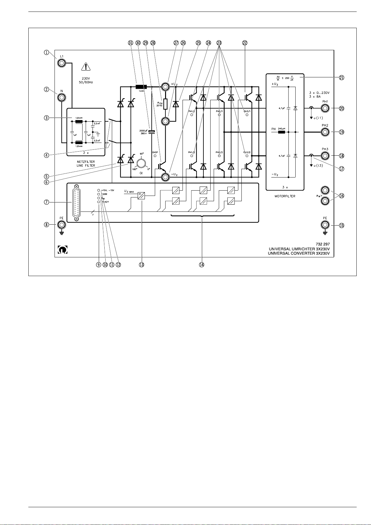
bn+15V, –15V - LED: indicates readiness, there is an internal
supply voltage for the electronic circuitry present.
boMonitoring device for the link voltage as well as the driver
with electronic isolation for the chopper transistor. The link
voltage is continuously compared with two critical values.
When the first threshold of approx. 355 V is exceeded, the
chopper transistor is switched on. This normally causes the
voltage to decrease until the chopper transistor switches off
again at approx. 350 V. It is conceivable that the voltage
continues to increase although the chopper transistor has
switched through. This can occur when attempting to rapid-
ly brake the machine without an additional external brake
resistor. Then the braking energy cannot be dissipated in
sufficient amounts and the voltage continues to increase
further. When the second threshold at 375 V is exceeded
then the inverter is switched off in order to interrupt the
braking process and prolong the braking time. This prevents
a further increase in the link voltage.
The chopper transistor can also be switched on with CHOPI
via the interface.
The switching status can be measured at the interface at
CHOPO.
bpSix drivers with galvanic isolation for controlling the power
transistors. Each of the six power transistors can be
switched on and off with the appropriate control signals
PH1/1...PH3/2. Here an interlocking logic element prevents
the transistors in a branch pair from both switching through
simultaneously. This is necessary as otherwise the link ca-
pacitors would short-circuit and thus cause the destruction
of the transistors.
The switching status of each individual transistor can be
recognized at the LEDs co.
brConnection of the thermostat of the machine. An open con-
tact signals excess temperature and brings about the sig-
nalling of a common error and thus the switch-off of the
converter. The excess temperature is indicated by the JM
LED bl, the common error is indicated by the IERR LED
bm. Switch-off enables the connected machine to cool off
and to the eventual renewed closing of the temperature
contact.
The JMLED bl goes out again but not the LED assigned to
indicate a general error. This ensures that the machine can
start up again automatically after a certain time period has
elapsed.
If a passive load without a thermostat is used, then this
contact can simply be short-circuited.
bsCurrent measurement: Depending on the application,
square-wave currents can flow with a frequency of up to
20 kHz at the three outputs of the frequency converter. But,
on the other hand, a pure DC current is possible. In order to
be able to measure such currents with sufficient accuracy
and also to be able to guarantee electronic isolation for the
current to be measured, these currents are detected with

6
sensoren mit magnetischer Sonde erfaßt und in eine propor-
tionale Spannung gewandelt:
UI
V
I
A
UI
V
I
A
1133
3
10
3
10
(
)
[]
=⋅
[]
(
)
[]
=⋅
[]
Die Messung des Stromes erfolgt nur an zwei Ausgängen,
da in einem symmetrischen Drehstromnetz damit auch der
dritte Strom bekannt ist. Denn es gilt: I1+ I2+ I3= 0
btUmrichter-Ausgang Phase 3; Anschluß W der Drehstromma-
schine.
buUmrichter-Ausgang Phase 2; Anschluß V der Drehstromma-
schine.
clUmrichter-Ausgang Phase 1; Anschluß U der Drehstromma-
schine.
cmDer Motorfilter wird eingesetzt zur Reduzierung der Flanken-
steilheit der gepulsten Ausgangsspannung des Umrichters
von ursprünglich 2000 V / ms auf Werte < 250 V / ms. Dies
wirkt sich günstig auf die Spannungsüberhöhung auf langen
Motorleitungen aus, schont die Isolierungen und vor allem
reduziert es die feld- und leitungsgebundene Störabstrah-
lung.
cnDer eigentliche Inverter mit sechs IGBT, schnellen Inversdi-
oden, Gate Drive- und Schutz-Logik ist in einem sogenann-
ten “Intelligenten Power Modul” integriert.
Grenzdaten der Brücke:
Max Kollektor-Emitter-Spannung UCES = 600 V
max. Kollektor Strom IC= 15 A
TypischeSchaltzeiten:
tON = 0,6 ms
tOFF = 2,0 ms
max. PWM-Frequenz: 20 kHz
Durchlaßeigenschaften IGBT und Diode:
Sättigungsspannung bei IC= 30 A
UCE(sat) = typ. 1,8 V (max 2,5 V)
Schleusenspannung Diode bei –IC = 15 A
– UCE = typ. 2,5 V (max. 3,5 V)
Für einem Spitzenwert des Kollektorstromes von IC= 30 A
ergibt sich bei sinusförmigem Strom rechnerisch ein maxi-
maler Effektivwert von 21 A.Wegen der überlagerten Strom-
oberwellen und des begrenzten Stromes des speisenden
einphasigen Netzes (16 A) muß der maximale Daueraus-
gangsstrom mit 8 A festgelegt werden.
coSchaltzustandanzeige der sechs Leistungstransistoren.
Siehe.
bp
cpMinuspol der Zwischenkreisspannung. Keine Erd- und Kurz-
schlußfähigkeit.
cqCollektor des Choppertransistors, Anschluß für externen
Chopperwiderstand
crFreilaufdiode des externen Bremswiderstand.
csPlus-Pol der Zwischenkreisspannung, Anschluß für exter-
nen Chopperwiderstand. Keine Erd- und Kurzschlußfähig-
keit.
ctInterner Bremswiderstand 20 kWund Anschlußmöglichkeit
für einen externen Bremswiderstand. Der eingebaute Chop-
perwiderstand ist nicht in der Lage nennenswerte Bremsen-
ergie aufzunehmen. Er ist nur gedacht als Hilfe beim Oszil-
loskopieren der Chopperfunktion. Wird die Bremsfunktion
benötigt, so ist ein externer Bremswiderstand von 100 Wpar-
allel zu dem 20 kWWiderstand, also zwischen den Kollektor
des Bremstransistors cr und den Pluspol der Zwischen-
kreisspannung cs anzuschließen. Ist der Bremswiderstand
nicht vorhanden, so kann es bei Bremsvorgängen zum
Schutz des Umrichters zu einer Abschaltung kommen.
compensation-current sensors with magnetic probes and
converted into a proportional voltage:
UI
V
I
A
UI
V
I
A
1133
3
10
3
10
(
)
[]
=⋅
[]
(
)
[]
=⋅
[]
The measurement of the current is only performed at two
outputs, since in a symmetrical three-phase mains the third
current is then also known. This is because the following
applies: I1+ I2+ I3= 0
btConverter output phase 3; terminal W of the three-phase
machine.
buConverter output phase 2; terminal V of the three-phase
machine.
clConverter output phase 1; terminal U of the three-phase
machine.
cmThe motor filter is used to reduce the steepness of slope of
the pulsed output voltage of the converter from the original
2000 V / ms to values < 250 V / ms. This has a positive effect
on the excess voltage on long motor leads, spares the insu-
lation and above all reduces the field and line-bound distur-
bance radiation.
cnThe actual inverter with six IGBTs, fast-acting inverting di-
odes, gate drive and protective logic circuitry has been inte-
grated into a so-called “Intelligent Power Module”.
Limiting data of the bridge:
Max. collector-emitter voltage UCES = 600 V
Max. collector current IC= 15 A
Typical switching times:
tON = 0.6 ms
tOFF = 2.0 ms
max. PWM frequency: 20 kHz
Forward characteristics IGBT and diode:
Saturation voltage for IC= 30 A
UCE(sat) = typical 1.8 V (max.2.5 V)
Threshold voltage for diode with –IC = 15 A
– UCE = typical 2.5 V (max. 3.5 V)
When we have a peak value of the collector current of IC=
30 A, the mathematical result in the case of a sinusoidal
current is a maximum rms value of 21 A. Due to the super-
imposed current harmonics and the limited current of the
feeding single-phase mains (16 A), the maximum continu-
ous output current must be restricted to 8 A.
coSwitching status indicator of the six power transistors.
See
bp
cpNegative pole of the link voltage. No earth-fault and short-
circuit proof capacity.
cqCollector of the chopper transistor, connection for external
chopper resistor
crFree-wheeling diode of the external brake resistor.
csPositive pole of the link voltage, connection for external
chopper resistor. No earth-fault or short-circuit proof capaci-
ty.
ctInternal brake resistor 20 kWand connection possibility for
an external brake resistor. The built-in chopper resistor can-
not absorb any considerable brake energy. It is only thought
of as an aid to help display the chopper function on the os-
cilloscope. If the brake function is needed, then an external
brake resistor of 100 Whas to be connected in parallel to
the 20 kWresistor, i.e. between the collector of the brake
transistor cr and the positive pole of the link voltage cs. If

7
cuChoppertransistor mit LED zur Anzeige des Schaltzustan-
des. Der Choppertransistor wird automatisch durchgeschal-
tet wenn die Zwischenkeisspannung 355 V überschreitet.Er
wird wieder ausgeschaltet wenn sie unter 350 V fällt.
Siehe
bo.
dlZwischenkreiskondensator: ACHTUNG ! Er kann noch bis 4
Minuten nach dem Abschalten berührungsgefährliche Span-
nung führen.
Über den Eingangsbrückengleichrichter und eine Glättungs-
drossel wird der Zwischenkreiskondersator geladen. Dieser
hat eine Kapazität von ca. 2000 mF und glättet die Zwischen-
kreisspannung.Er muß ebenfalls in der Lage sein mit hoher
Pulsfrequenz Energie an den Inverter zu liefern oder über
die Inversdioden zurückgelieferte Energie aufzunehmen. Er
ist spannungsfest bis 385 V.
dmGlättungsdrossel, L = 11 mH, zur Reduzierung der Lade-
stromspitzen
the brake resistor is not present, then switch-off can occur
during braking process in order to protect the converter.
cuChopper transistor with LED for the indication of the switch-
ing status.The chopper transistor is automatically switched
through when the link voltage exceeds 355 V. It is switched
off again when voltage drops below 350 V. See point bo.
dlLink capacitor: WARNING ! It can carry contact-hazardous
voltage for up to 4 minutes after switch-off.
The link capacitor is charged up via the input bridge rectifi-
er and a smoothing reactor. This has a capacitance of ap-
prox. 2000 mF and smooths the link voltage. It must also be
in a position to supply power to the inverter with high pulse
frequency or to absorb power supplied back via the inverse
diodes. It is voltage-proof up to 385 V.
dmSmoothing reactor, L = 11 mH, for the reduction of the
charge current peaks
3 Bedienung
Ein sinnvoller Betrieb ergibt sich nur in Verbindung mit einem
der eingangs genannten Steuergeräte. In den jeweiligen Ge-
brauchsanleitungen dieser Steuergeräte ist die Bedienung aus-
führlich erklärt, so daß dies hier unterbleiben kann.
3 Operation
This device can only be operated sensibly in conjunction with
one of the control units mentioned at the beginning of this text.
Operation information is discussed in depth with in the respec-
tive instruction sheets of these control units so that further in-
formation regarding this point can be dispensed with here.
Other LEYBOLD Media Converter manuals