LEYBOLD TURBOTRONIKNT 340 M User manual

TURBOTRONIK
NT 340 M
NT 340 MA
NT 341 MA
Electronic frequency
converters
Cat.No.
857 29/30/31
857 32
857 34
Operating Instructions
GA 05.218/3.02
Vacuum Solutions Application Support Service LEYBOLD VACUUM
(505)872-0037
idealvac.com
idealvac.com

Description
Contents
Page
1Description . . . . . . . . . . . . . . . . . . . . . . . . . . 2
1.1 Design and Function . . . . . . . . . . . . . . . . . . . 2
1.2 Standard Specification . . . . . . . . . . . . . . . . . . 3
1.3 Technical Data . . . . . . . . . . . . . . . . . . . . . . . . 5
1.4 Ordering Data . . . . . . . . . . . . . . . . . . . . . . . . 6
2Connection . . . . . . . . . . . . . . . . . . . . . . . . . . 7
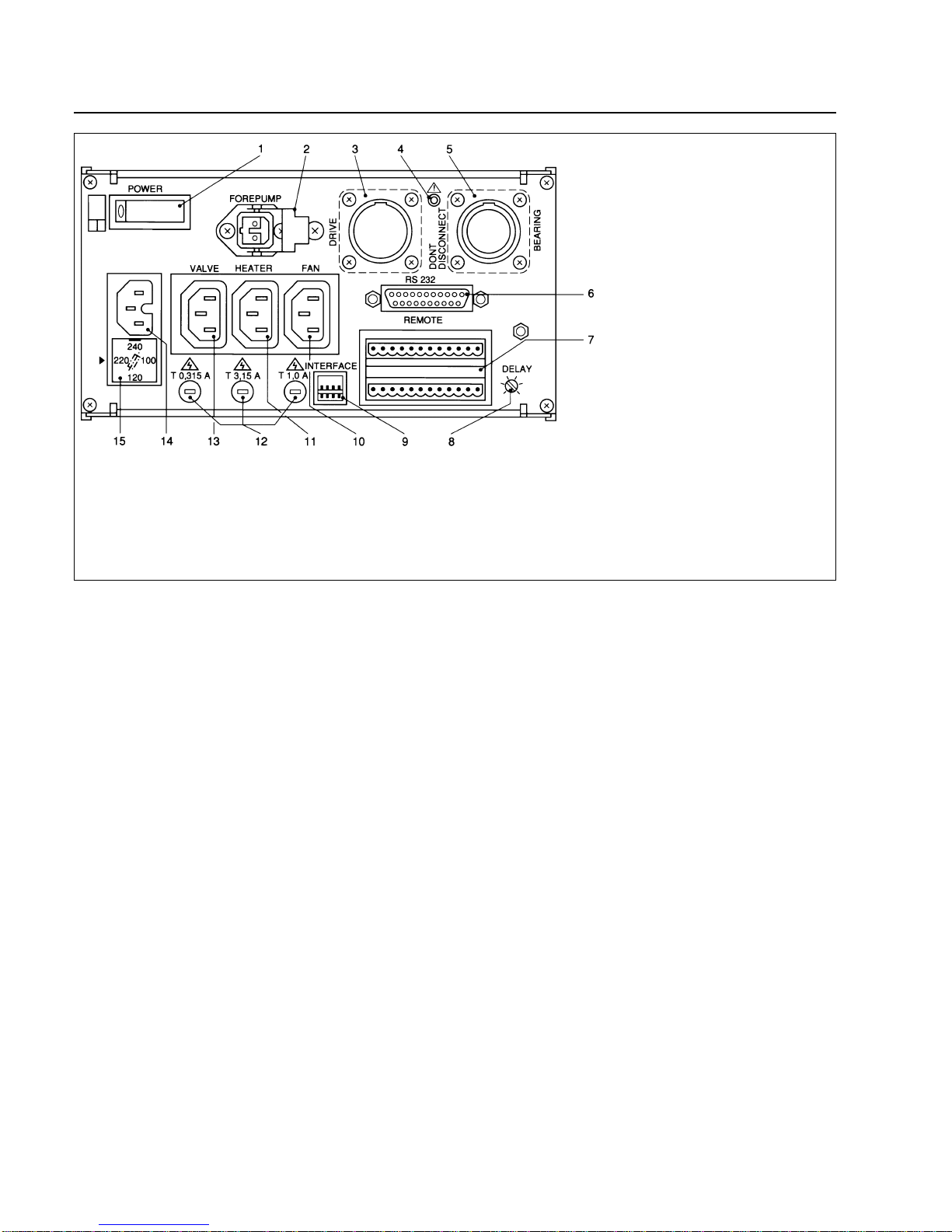
2.1 Setting the Mains Voltage . . . . . . . . . . . . . . . 7
2.2 Connecting the TURBOVAC . . . . . . . . . . . . . . 7
2.3 Connecting the Forevacuum Pump . . . . . . . . 7
2.4 TURBOTRONIK NT 340 M & MA without
temperature control (TCU):
Connecting the Cooling, Venting Device
and the Flange Heater . . . . . . . . . . . . . . . . . 8
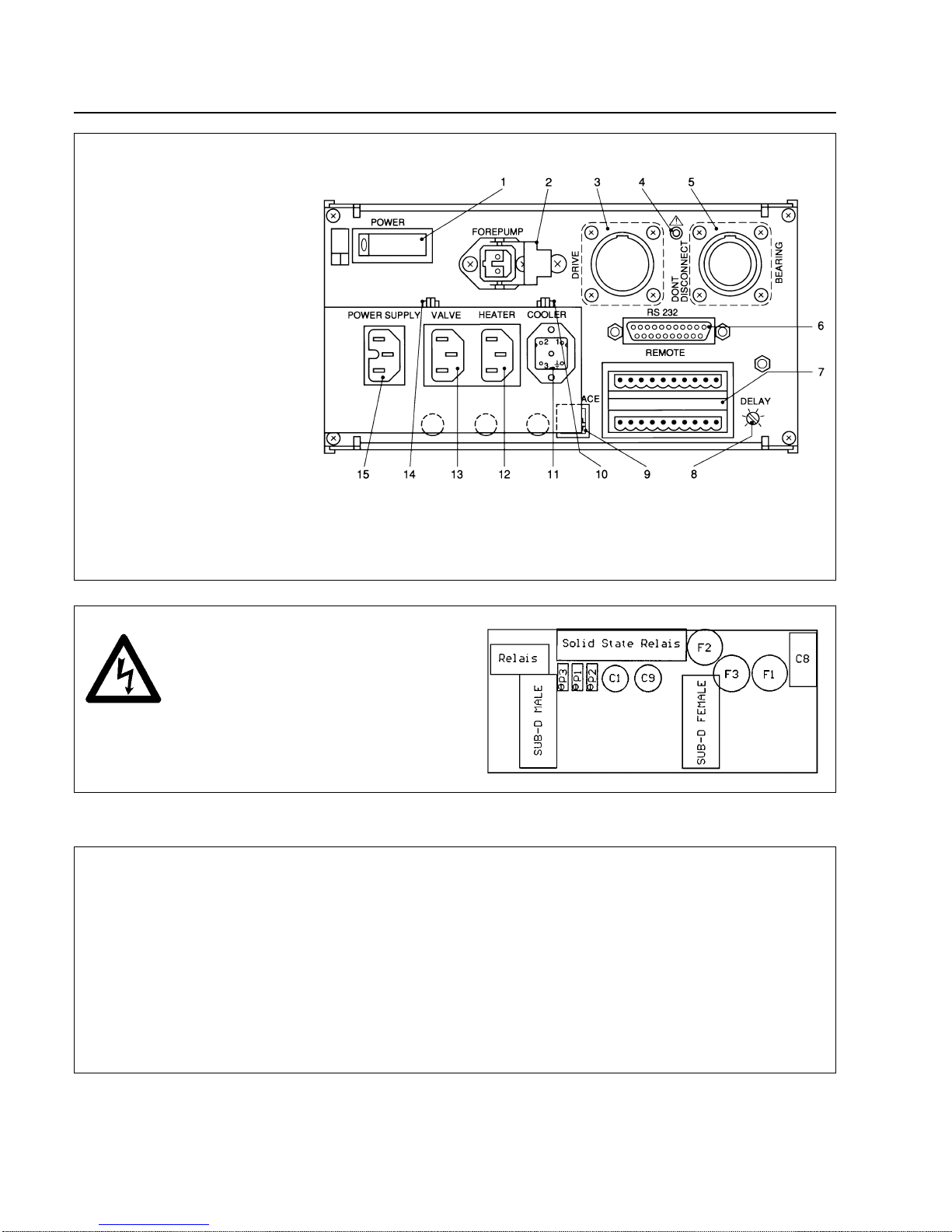
2.5 TURBOTRONIK NT 340 MA with
temperature control (TCU):
Connecting the Temperature Control
and the Forevacuum Valve. . . . . . . . . . . . . . 10
2.6 TURBOTRONIK NT 341 MA:
Connecting the Temperature Control
and the Forevacuum Valve. . . . . . . . . . . . . . 12
2.7 Connecting the Interface . . . . . . . . . . . . . . . 14
2.8 Connecting the Remote Control . . . . . . . . . . 14
2.9 Modifying the Relay “Failure” (Option) . . . . . 16
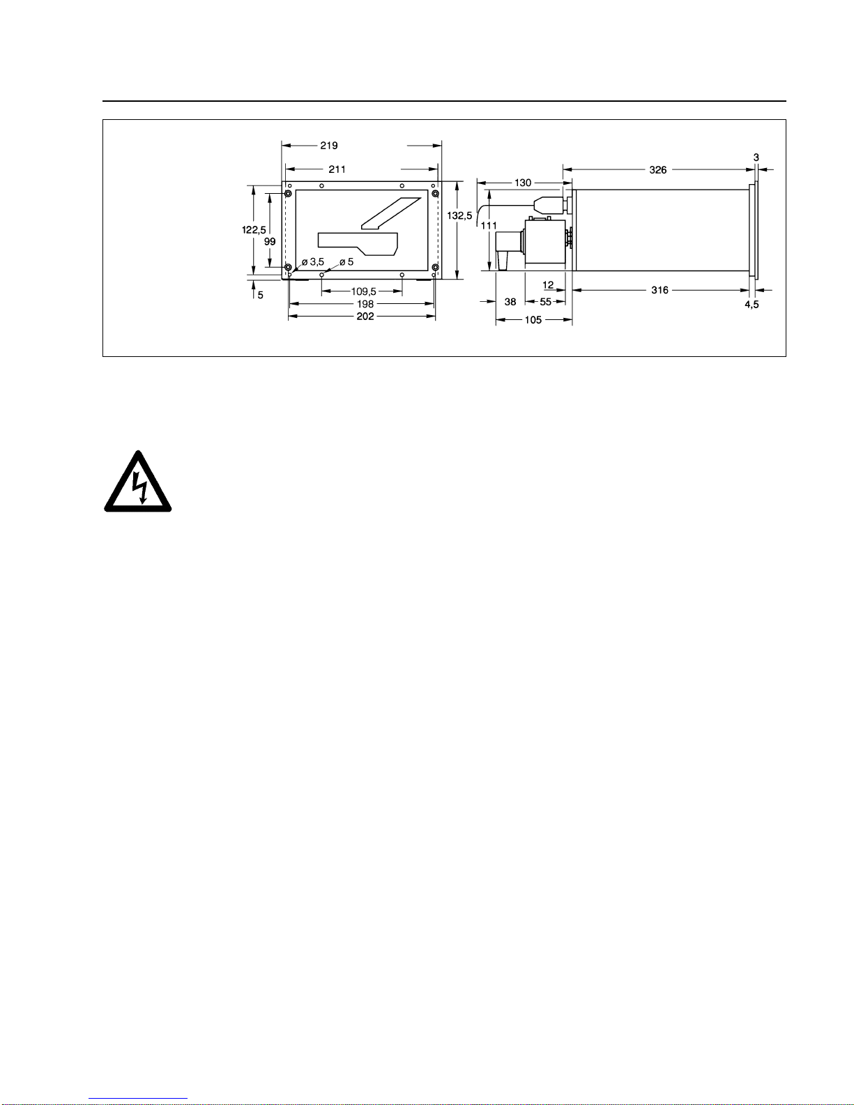
2.10 Installing the TURBOTRONIK . . . . . . . . . . . 16
3Operation . . . . . . . . . . . . . . . . . . . . . . . . . . 18
3.1 Start-up . . . . . . . . . . . . . . . . . . . . . . . . . . . . 18
3.2 Start-up of the TURBOVAC . . . . . . . . . . . . . 18
3.3 Bakeout of the TURBOVAC . . . . . . . . . . . . . 18
3.4 Operation . . . . . . . . . . . . . . . . . . . . . . . . . . 19
3.5 Shut-down of the TURBOVAC . . . . . . . . . . . 19
3.6 Venting of the TURBOVAC . . . . . . . . . . . . . . 19
3.7 Power Failure - Linecord Interruption . . . . . . 19
3.8 Shut-down of the TURBOTRONIK . . . . . . . . 20
3.9 Maintenance . . . . . . . . . . . . . . . . . . . . . . . . 20
4 Troubleshooting . . . . . . . . . . . . . . . . . . . . . . 21
EC Conformance Declaration . . . . . . . . . . . . 22
Warning
Indicates procedures that must be strictly observed to prevent
hazards to persons.
Caution
Indicates procedures that must be strictly observed to prevent dam
age to, or destruction of the appliance.
Figures
The references to diagrams, e. g. (2/10), consist of the Fig. No. and
the Item No.in that order.
We reserve the right to alter the design or any data given in these Op
erating Instructions.
The illustrations are not binding.
1 Description
1.1 Design and Function
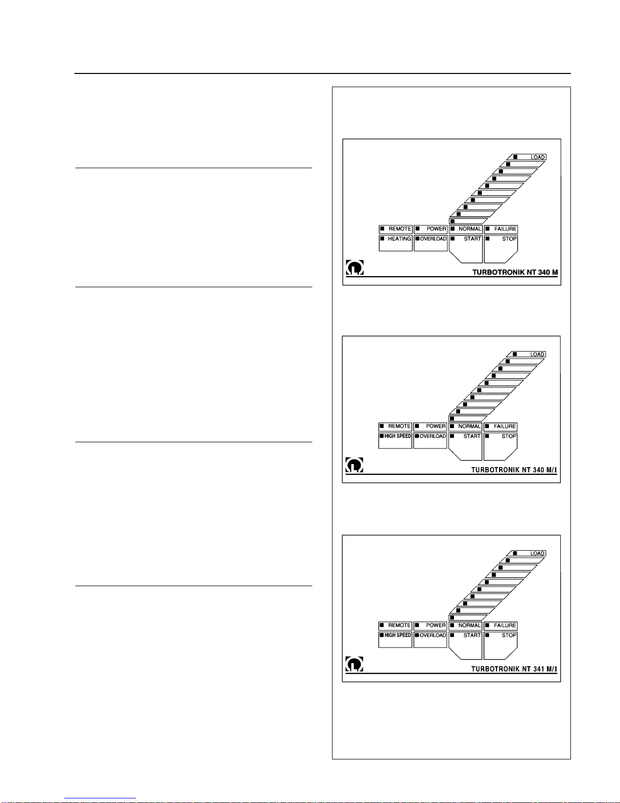
TheTURBOTRONIK NT 340 M, NT 340 MA, and NT 341
MA are electronic frequency converters.They operate
turbomolecular pumps TURBOVAC.
The TURBOTRONIK NT 340 MA and NT 341 MA are
prepared for operation with an additional temperature
control unit. This temperature control unit is part of a
temperature control which maintains the temperature of
the TURBOVAC within a narrow control range.
The TURBOTRONIK converts the single-phase mains
voltage into a regulated DC power supply.The unit’s
electronic circuitry then switches this DC power supply
onto the four stator windings of the TURBOVAC’s com-
mutatorless DC motor in a cyclical sequence.
This electronic switching system uses Hall probes, and
replaces the commutator normally found in DC motors.A
digital controller keeps the speed of the motor constant.
The TURBOTRONIK also powers and regulates the
magnetic bearing unit. Switching the motor to the gen-
erator mode keeps the magnetic bearing unit in operati-
on even in case of a mains power failure.
Both the TURBOTRONIK and the TURBOVAC are fitted
with sensors to ensure reliable operation of the entire
system. External control and monitoring equipment e.g.
the LEYBOTRONIK I can be connected via floating plug-
and-socket terminals located at the rear of the TUR-
BOTRONIK. Both the remote control unit and the lines
for the pump system’s status signals are connected here.
These terminals also provide connections for controlling
the forepump, the heater and valves.
An RS-232 interface provides a further control and mon-
itoring option.
The unit also has a counter-current braking system for
slowing down the pump when it is shut down.
2GA 05.218/3.02 - 11/97

GA 05.218/3.02 - 11/97
Description
3
1.2 Standard Specifications
TURBOTRONIK NT 340 M
Mains voltage
setting Cat. No.
for TURBOVAC
230 V857 29 340 M, MC, 400 MC
120 V857 30
Standard Specification
Power linecord, Miniature fuses: 2 T 8.0 A; 2 T 4.0 A;
2 T* 3.15 A; 2 T1.0 A; 2 T 0.5 A; 2 T 0.315 A
3 mains plugs, 2 terminal strips,
1 portable socket-outlet
Mains voltage
setting Cat. No.
for TURBOVAC
100 V857 31 340 M, MC, 400 MC
Standard Specification
Power linecord, Miniature fuses: 2 T 4.0 A;
2 T 3.15 A; 2 T1.0 A; 2 T 0.5 A; 2 T 0.315 A
3 mains plugs, 2 terminal strips,
1 portable socket-outlet
TURBOTRONIK NT 340 MA
Mains voltage
setting Cat. No.
for TURBOVAC
120 V857 32 340 M, 340 MC
340 MCT
400 MC, 400 MCT
Standard Specification
Power linecord, Miniature fuses: 2 T 8.0 A; 2 T 0.5 A;
TURBOTRONIK NT 341 MA
Mains voltage
setting Cat. No.
for TURBOVAC
208 V857 34 341 MCT, 410 MCT
Standard Specification
Power linecord (mounted),
Miniature fuses 4 T 5.0 A, 2 T 0.5 A
Connection lines to the TURBOVAC do not belong to
the standard specifications.
*T= slow-blowFig. 1 Front panels of the TURBOTRONIK,
explanation see table 1 and 2

GA 05.218/3.02 - 11/97
Description
Table 1: Operational Status Display of the Front Panel LEDs
LED Color Display
LOAD green LED “START” lights up: speed of the TURBOVAC (individual LED, linear display)
(LED chain) LED “STOP” lights up: speed of the TURBOVAC (individual LED, linear display)
LED “OVERLOAD” lights up: speed of the TURBOVAC (individual LED, linear display)
LED “NORMAL”lights up: motor current (LED chain, logarithmic display)
LED “FAILURE” lights up: failure code (one LED “LOAD” flashes)
REMOTE yellowLights up when the converter is controlled via the remote control inputs or via the interface;
key manipulation is ignored.
Flashes when control is possible both via keyboard and the RS 232 interface.
POWER green Lights when mains power supply is on.
NORMAL green Lights during normal operation, speed is above 95 % of the target speed
Flashes in case of acceleration, braking and “OVERLOAD”.
FAILURE red Lights in case of failure.
Flickers in case of current peaks within the magnetic bearings.
HEATING green Lights when heating is on.
only on NT 340 M Flashes when heating has been preselected.
HIGH SPEED green Lights when the TURBOVAC runs with high speed (51,600 min-1).
only on NT 340 MA
and NT 341 MA
OVERLOAD yellowLights in case of overload, i. e. speed is below 95 % of the target speed having finished
the acceleration sequence.
START green Lights in case of TURBOVAC’s acceleration.
Flashes when the delay start-up time is active.
STOP green Lights when the TURBOVAC brakes.
Table 2: Functions of the Front Panel Keys
Key Functions
HEATING Switching the TURBOVAC’s heating on and off.
only on NT 340 M
HIGH SPEED Selecting high or optimized speed for TURBOVAC.
only on NT 340 MA see Section 3.1.
and NT 341 MA
START Starting the TURBOVAC’s acceleration.
STOP Braking the TURBOVAC.
Resetting a failure report.
4

GA 05.218/3.02 - 11/97
Description
5
1.3 Technical Data
Mains voltage, with selector switch
100/120/220/240 V,+10%/-15%
Mains frequency 50/60 Hz
Power consumption
including all connected units <1000 VA
Power consumption of theTURBOVAC <400 VA
Rated speed of the TURBOVAC 43,860 / 51,600 min-1
Minimum speed of the TURBOVAC 6,000 min-1
Power output (motor)
Nominal voltage 50 V
Current limitation 7 A
Power output for the magnetic bearing
Nominal voltage ±16 V
Current limitation ±7 A
Control Inputs - digital, floating
each terminal 25 Veff AC max., 60 V DC
versus protective conductor
LEYBOTRONIK I compatible
High level; between “+” and “-” terminal
13 V...33 V/max. 10 mA
Low level; between “+” and “-” terminal 0 V...7 V
Pulse duration >200 ms
for remote control active “START” pump,
“STOP” pump, heater On/Off
Target speed analog input, not isolated
Setting range 0...10 V
Rated Speed 0 V
Minimum Speed 10 V
Control Outputs
Relay25 Veff AC, 60 V DC, 2 A/60 W/125 VA
for normal operation operating contact
for acceleration operating contact
for failure resting contact, switchable
to operating contact
Analog voltage 0...10 V
selectionable speed or motor current proportional
Loadable max. 5 mA
Standstill, no current corresponds to 0 V
Rated speed, max. current corresponds to 10 V
Reference voltage 15 V, max. 20 mA
(not isolated for speed potentiometer and remote
control inputs)
Forevacuum pump “FOREPUMP”;
Relay point 6 A, 750 VA, 250 V
Supply Outlets NT 340 M & MA
Voltage value corresponds to mains voltage
VALVE max. 20 VA
HEATER max. 300 VA
FAN max. 100 VA
For 100 V and 120 V connection: sum of the supply out-
lets (VALVE, HEATER, FAN) max. 400 VA
Interface RS 232/V.24
Connector 25-pin, D-shell, female
Baud rate 4,800 or 9,600
Operating temperature;
with sufficient free convection 0-45
°C (32°F - 113°F)
Storage temperature -25°C...+70°C (-77°F - +158°F)
Interference elemination
ISM appliance group 1, Limit value class A
according to EN 50081-2 / EN 55011
Interference resistance
Electrostatic discharge (ESD)
IEC 801-2, VDE 0843, Part 2 Severity 4
Burst IEC 801-4, VDE 0843, Part 4 Level III
high-energy impulse
IEC 801-5, VDE 0843, Part 5 Level III
Weight approx. 7 kg
Temperature control unit: supply outlets
Voltage corresponds to mains voltage
Heating collar “HEATER” max. 120 W
Cooling water magnetic valve “COOLER” max. 30 W
Forevacuum valve “VALVE” max. 120 W
Temperature control unit: fuses
F1 and F2 T 1.6 A
F3 T 0.315 A

GA 05.218/3.02 - 11/97
1.4 Ordering Data
Ref.No.
Pump system control LEYBOTRONIK I 013 10
Power unit for LEYBOTRONIK I upon request
Delaying venting device 012 44
Venting valve for delaying venting device 012 45
TURBOTRONIK NT 340 M
Connection line set for connecting
the TURBOVAC
3 m long 857 70
5 m long 857 71
10 m long 857 72
20 m long 857 73
TURBOTRONIK NT 340 MA
Connection line to the
TURBOVAC motor, 3 m long 859 10
Connection line to the
TURBOVAC bearing, 3 m long 859 11
Accessories for temperature control
Temperature control unit (TCU) 859 20
Temperature sensor Pt 100 859 22
Connection lines
to the heater 859 31
to the cooling water magnet valve (COOLER) 859 32
to the valve859 33
to the temperature control unit (I/O) 859 34
to the Pt 100 859 39
TURBOTRONIK NT 341 MA
Connection line to the
TURBOVAC motor, 20 m long 859 12
Connection line to the
TURBOVAC bearing, 20 m long 859 13
Accessories for temperature control
Temperature control unit (TCU) 859 21
Temperature sensor Pt 100 859 22
Connection lines
to the valve859 33
to the temperature control unit (I/O) 859 34
mains connection line to the temperature
control unit 859 35
to the Pt 100 859 36
to the cooling water magnet valve (COOLER) 859 37
Description
6
Fig. 2a Dimensional drawings of TURBOTRONIK , dimensions in mm
NT 340 MA
NT 341 MA similar
NT 340 M
(Front panel)
(Housing)
(Front panel)
(Housing)

GA 05.218/3.02 - 11/97
Connection
7
2 Connection
Warning Connections for forevacuum pump, cooling,
venting valve and flange heater must be
done by a qualified electrician in accord-
ance with the applicable safety regulations.
2.1 Setting the Mains
Voltage
The TURBOTRONIK has been set at the factory for a
mains power supply; see Section „1.2 Standard Specifi-
cation“.
To change this setting, remove the dummy plug (3/15)
with a screwdriver and reinsert it according to the stam-
ped-on voltage setting. The selected voltage indication
must be in the immediate proximity of the arrow.
If you do change the voltage setting, please also change
the line power fuse accordingly; see the table.
Fuses
LINE VALVE HEATING FAN
————————————————————————
100 VT*) 4.0 A T 0.315 A T 3.15 A T 1.0 A
120 VT 8.0 A T 0.315 A T 3.15 A T 1.0 A
220/240 VT 4.0 A T 0.315 A T 3.15 A T 1.0 A
(*) slow-blow)
In case of need, other fuses may be installed for VALVE,
HEATING and FAN. However, the sum of the fuses’
capacity for the three connections must not exceed:
4.5 A for 100/120 V
6.0 A for 220/240 V.
Plug the power linecord into the socket (3/14), (5/15).
The NT 341 MT has a fixed linecord.
2.2 Connecting the
TURBOVAC
Insert and fasten the connection line to the motor of the
TURBOVAC at the socket DRIVE and to theTURBOVAC
itself.
Insert and fasten the connection line to the stabilizer and
axial sensor of the TURBOVAC at the socket BEARING
and to the TURBOVAC itself; both plugs are non-inter-
changeable.
2.3 Connecting the
Forevacuum Pump
Connect the forepump to the relay contact output FORE-
PUMP.When pressing the START key the contact is
closed without any delay and the forepump is switched
on.
The forepump is shut down when the TURBOVAC has
come to a standstill, switching examples see fig. 11.
A starting delay for the TURBOVAC can be set at the
potentiometer DELAY; see Section 3.1
NT 340 MA with
plugged-in temperature
control unit
(Front panel)
(Housing)
Fig. 2b Dimensional drawings of TURBOTRONIK , dimensions in mm

GA 05.218/3.02 - 11/97
2.4
NT 340 M & NT 340 MA with-
out temperature control:
Connecting the Cooling,Ven-
ting Device and the Flange
Heater
Cooling
The mains power supply to the socket (3/10) is switched
on as soon as the TURBOVAC acceleration sequence
begins; max. load 100 VA. The relevant fuse (3/12) is
below the socket.
The power supply to the socket is switched off once the
TURBOVAC has come to a standstill and when the
power switch is turned off.
A magnetic valve for the water cooling or a fan can be
connected to the socket (3/10).
Venting
The mains power supply to the socket (3/13) is switched
on without any delay when START is activated. The
power is turned off when STOP or FAILURE are activa-
ted; max. load 20 VA. The relevant fuse (3/12) is below
the socket.
Caution Any interruption in power, no matter how
short, will cause the pump to be vented.
Power Failure Airing Valve
If theTURBOVAC is operated without purge gas a power
failure airing valve can be connected to socket (3/13)
VALVE.
Purge Gas- and Venting Valve
When operating the TURBOVAC with purge gas it must
be vented via the purge gas and venting valve.
Delayed Venting Device andVenting Valve
When shutting down or in case of a power failure the
connection of the delayed venting device allows for set-
ting the start and duration of the venting sequence in
order to protect a system or a process-procedure.
The presetting time can vary between 3 to 15 minutes.
A short power failure does not entail an unwanted ven-
ting.
Connect the delayed venting device to (3/13).
Connection
8
Key to Fig. 3
1 Power switch
2Relay contact for forevacuum pump
ON/OFF
3Connection for supply of the
TURBOVAC
4LED red, magnetic bearing active
5Connection for the magnetic bearing
of the TURBOVAC
6Connection socket for RS 232 inter-
face
7Connection terminal strip
8 Potentiometer for setting
the delay time
9 Parameter selection for RS 232
interface
10 Connection for fan or solenoid valve
for water cooling
11 Connection for heating
12 Fuses
13 Connection for venting valve
14 Connection for power linecord
15 Plug for selecting the mains
voltages with integrated fuse
Fig. 3 TURBOTRONIK NT 340 M & MA, rear panel

GA 05.218/3.02 - 11/97
Connection
9
FOREPUMP
BEARING
DRIVE
POWER FAN (COOLER)
VALVE
HEATER
N2
Fig. 4 Block wiring diagram for TURBOVAC 340 M & MC & 400 MC and NT 340 M & MA
Flange Heater
(Only for pumps with CF connection flange)
The mains power supply to the socket (3/11) is switched
on when HEATING is activated, provided that the pump
operation status is NORMAL; max load 300 VA.
The relevant fuse (3/12) is below the socket.
Connect the flange heater to the TURBOVAC at socket
(3/11) “HEATER”.

GA 05.218/3.02 - 11/97
Connection
10
Key to fig. 5
1 Power switch
2Relay contact for forevacuum
pump ON/OFF
3Connection for supply of the
TURBOVAC
4LED red, magnetic bearing
active
5Connection for the magnetic
bearing of the TURBOVAC
6Connection socket for RS 232
interface
7Connection terminal strip
8 Potentiometer for setting
the delay time
9 Parameter selection for RS 232
interface
10 Connection for voltage supply of
the temperature controller
11 Connection for cooling water
magnetic valve
12 Connection for heating collar
13 Connection for forevacuum valve
14 Connection for Pt 100
15 Connection of the power linecord
Fig. 5 TURBOTRONIK NT 340 MA with temperature control unit, rear panel
Warning Prior to opening the temperature control unit
pull it off.If the plug of the temperature control
unit is connected there may be line voltage
inside the unit.
Fig. 6 Location of the fuses F1, F2, F3 in the temperature control unit;
bottom removed
Table 3:Temperature Control Unit: Pin assignment of the Sub D Sockets
Sub D Socket VOLTAGE I/0 (Plug) Sub D Socket Pt 100 (Socket)
Pin 1 Relay contact* Linked with pin 2
Pin 2 Voltage of the Pt 100 (0.1 V corresponds to 1 °C) Pt 100
Pin 3 Common point for the relay* Pt 100
Pin 4 Voltage treshold „NORMAL“ Linked with pin 3
Pin 5 Relay contact* Linked with pin 3
Pin 6 Earthed (of NT:pin 21 of the socket REMOTE) Linked with pin 2
Pin 7 Voltage treshold „Pump too cold“ Linked with pin 3
Pin 8 Voltage treshold „Pump too hot“ Linked with pin 3
Pin 9 + 15 V (of NT:pin 210 of the socket REMOTE) Linked with pin 3
Voltage supply for temperature controller
* If the pump is too hot or too cold (FAILURE), the contact between pin 1 and 3 is closed and open between pin 3 and 5.
In the operation mode NORMAL of the temperature controller the contact between pin 1 and 3 is open and closed between pin 3 and 5.
Too hot:T > 75 °C (167°F); too cold:T < 55 °C (131°F); NORMAL: 55 °C ≤T ≤75 °C (131°F ≤T ≤167°F)

Connection
2.5
NT 340 MA with temperature
control: Connecting the
Temperature Control and the
Forevacuum Valve
Temperature control
The parts required for temperature control are listed in
Section 1.4.
Plug in the temperature control unit, see Fig. 5.
The temperature control controls the temperature of the
TURBOVAC 340 MCT & 400 MCT within a narrow con-
trol range.
Connect the connection line to the heating collar at the
heating collar of the TURBOVAC and at the socket HEA-
TER.
Plug in the connection line to the cooling water magnetic
valve at the cooling water magnetic valve of theTURBO-
VAC and at the socket COOLER.
Plug the connection line of the Pt 100 of the TURBOVAC
into the socket Pt 100.
Plug in the connection line temperature control unit -
TURBOTRONIK at the sockets VOLTAGE I/O and
REMOTE.
Forevacuum valve
The socket VALVE is supplied with current provided the
mains voltage is applied, max. rate: 120 W.
A heater for a forevacuum valve can be connected to the
socket.
11
GA 05.218/3.02 - 11/97
FOREPUMP
BEARING
DRIVE
POWER
TCU
HEATER
COOLER
Pt 100
VALVE
N2
Fig. 7 Block wiring diagram for TURBOVAC 340 MCT & 400 MCT and NT 340 MA with temperature control

Connection
2.6 NT 341 MA:
Connecting the Temper-
ature Control and the
Forevacuum Valve
Temperature control
The parts required for temperature control are listed in
Section 1.4.
Install the temperature control unit.
The temperature control controls the temperature of the
TURBOVAC 341 MCT & 410 MCT within a narrow con-
trol range.
The temperature control unit has to be connected to 120
V AC mains voltage.
Warning The power supply must ensure that even in
case of failure no lethal voltages may occur.
Connect the connection line of the heating collar at the
socket HEATER.
Plug in the connection line to the cooling water magnetic
valve at the cooling water magnetic valve of theTURBO-
VAC and at the socket COOLER.
Plug the connection line of the Pt 100 of the TURBOVAC
into the socket Pt100.
Plug in the connection line temperature control unit -
TURBOTRONIK at the sockets VOLTAGE I/O and
REMOTE.
Forevacuum valve
The socket VALVE is supplied with current provided the
mains voltage is applied, max. rate: 120 W.
A heater for a forevacuum valve can be connected to the
socket.
12 GA 05.218/3.02 - 11/97
Key to Fig. 8
1 Power switch
2Relay contact for forevacuum
pump ON/OFF
3Connection for supply of the
TURBOVAC
4LED red, magnetic bearing active
5Connection for the magnetic
bearing of the TURBOVAC
6Connection socket for RS 232
interface
7Connection terminal strip
8 Potentiometer for setting
the delay time
9 Parameter selection for RS 232
interface
10 Power linecord
11 Fuses power supply
Fig. 8 TURBOTRONIK NT 341 MA, rear panel

GA 05.218/3.02 - 11/97
Connection
13
COOLER HEATER VALVE POWER
SUPPLY
VOLTAGE I/O Pt 100
Fig. 10 Temperature Control Unit, dimensions in mm
FOREPUMP
BEARING
DRIVE
POWER
TCU
HEATER
COOLER
Pt 100
VALVE
POWER
N2
Fig. 9 Block wiring diagram for TURBOVAC 341 MCT & 410 MCT and NT 341 MA with temperature control
127 138,5
4,4
25,5
31,8
60
7,6

Connection
2.7 Connecting the Interface
A description of the interface for operating the TUR-
BOTRONIK with a computer can be ordered under the
description SB 05.207.
The parameters for the interface will be set at the DIP
switches.
At DIP switch 1 you can choose whether the analog out-
put voltage at the terminal strip REMOTE will rise pro-
portionnally to the motor current or the speed.
ON analog output = motor current LOAD.
OFF analog output = SPEED.
2.8 Connecting the Remote
Control Unit
For the signal assignments of the terminal strip REMO-
TE refer to fig. 12.
Switching examples see fig. 13.
Technical Data see section 1.3.
Relay statuses see table 4.
Note for Switching Example ON/OFF Switch
If instead of the ON-OFF switch a jumper is established
between Pin 4 and 20, theTURBOVAC will start up auto-
matically once the TURBOTRONIK is switched on.
Caution The maximum permissible voltage at each
of the terminals is 25 Veff AC, 60 V DC ver-
sus protective conductor.
Inputs
-Remote control active
REMOTE Disables the keys and activates the
remote control inputs
(continuous signal; High-active)
START pump Impulse or continuous signal;
High-active
STOP pump Impulse or continuous signal;
Low-active
HEATING Heating ON/OFF steady-state
signal; High = On, Low = Off
Speed (target value) analog signal
Due to safety reasons the STOP function (Low-active) is
dominant.
In order to start the TURBOTRONIK via the remote con-
trol:
the REMOTE-inputs must be activated
i.e.high-level between “+” and “-” terminal,
the STOP-inputs must be inactivated
i.e.high-level between “+” and “-” terminal,
the START-inputs must be activated
i.e.high-level between “+” and “-” terminal.
Outputs
Acceleration,
Normal operation,
Failure,
Current-/speed actual value,
The reference voltage is +15 V for speed potentiometer
and remote control inputs.
The reference voltage is protected by the fuse F7. Posi-
tion of the fuse se fig.14. For changing the fuse open the
TURBOTRONIK as described in section 2.9.
14 GA 05.218/3.02 - 11/97

GA 05.218/3.02 - 11/97
Connection
15
Relay status VALVE HEATER FAN FOREPUMP ACCEL FAILURE NORMAL
(3/13) (3/11) (3/10) (3/2) Fig. 12 Fig. 12 Fig. 12
Power off open open open open open closed** open
Standstill open open open open open closed** open
Delayed start-up device closed open open closed closed closed** open
Acceleration closed open closed closed closed closed** open
NORMAL closed closed* closed closed open closed** closed
Overload closed closed* closed closed open closed** closed
Braking open open closed closed open closed** open
Failure;TURBOVAC rotates open open closed closed open open** open
Failure;TURBOVAC stands still open open open open open open** open
* if selected ** modifications possible
Key to Fig. 6
Inputs
L=LOW; H=HIGH
1REMOTE “-”
2REMOTE “+”
3“STOP” “-”
4“STOP” “+”
5not used
6not used
7“START” “-”
8“START” “+”
9HEATING “-”
10 HEATING “+”
11 not used
12 not used
The inputs are
opto-coupled
Fig. 11 Switching examples for the motor connection of the forevacuum pump
Power <750 VA /single-phase Power >750 VA /single-phase three-phase
Inputs
Outputs
Outputs
13 NORMAL Target speed
14 NORMAL attained
15 FAILURE
16 FAILURE
17 Acceleration (ACCEL)
18 Acceleration (ACCEL)
19 not used
20 +15 V
21 earthed
22 Analog output voltage
0...10 V
23 earthed
24 Speed target value, 10...0 V
Fig. 12 TURBOTRONIK rear panel;
assigment of the terminal strip REMOTE
H=active
L=active
H=active
H=active
Table 4

Connection
2.9 Modifying the Relay
FAILURE (Option)
On delivery the relay FAILURE is a resting contact (nor-
mally closed). It can be changed to an operating contact
(normally open).
Warning Before you open the TURBOTRONIK
please first ensure that the TURBOVAC has
been braked to a complete standstill, and
that the mains power cord is disconnected.
Since, nonetheless dangerous voltages
may occur the unit must only be opened by
a qualified electrician.
For modifying the relays, remove the fastening screw of
the upper cover sheet at the rear and pull out the upper
cover sheet.
Modify the jumper (14/2).
State of deliveryresting contact 1-2
Modification operating contact 2-3
Close the TURBOTRONIK again.
We recommend noting all the modifications made on the
unit itself or at least in the Operating Instructions for that
particular instrument.
2.10 Installing the
TURBOTRONIK
Install the TURBOTRONIK.
The heat dissipation of the TURBOTRONIK must not be
obstructed. Insure a sufficient ventilation - the ambient
temperature during operation must not exceed 45°C
(113°F).
If - after installation - the rear of the TURBOTRONIK
is no more accessible, switch on the POWER switch
before mounting and if nec.set the starting delay;refer to
section 3.1.
Warning If the TURBOTRONIK is built into a rack the
mains plug is not within easy reach. There-
fore install a separation between the TUR-
BOTRONIK and the mains when you build it
into a rack.
Warning Do not operate theTURBOTRONIK with the
standard mains lead in chemically aggressi-
ve surroundings.If you operate the TUR-
BOTRONIK in chemically aggressive surro-
undings replace the mains lead by a resi-
stant one.
16 GA 05.218/3.02 - 11/97

GA 05.218/3.02 - 11/97
Connection
17
Key to Fig. 14
1Relay
2 Jumper
3Connection plug for the RS 232 interface
4Fuses
F7 Fuse for 15 V at Pin 20 of the
terminal strip REMOTE
Fig. 14 Position of the jumper for the relay failure;
top view into the TURBOTRONIK
Terminals No.
Terminals No.Terminals No.
active = 13 V ... 33 V
inactive = 0 V ... 7 V
active = 0 V ... 7 V
inactive = 13 V ... 33 V
active = 13 V ... 33 V
inactive = 0 V ... 7 V
Active control with a voltage signal;
LEYBOTRONIK I compatible
Via continuous contact, remote control
via key; passive control with contacts Via continuous contact, ON/OFF
switch; passive control with contacts
Fig. 13 Connection of the remote control

Operation
3 Operation
3.1 Start-up
Insert the power plug.
Switch on the POWER switch.
Having switched on the power switch the TURBOVAC’s
stabilizer is activated and the rotor lifts up.
Afterwards all LEDs light up for approx. 2 s for a func-
tional check.The green LED „POWER“ remains on.
On the TURBOTRONIK NT 340 MA and 341 MA with
temperature control the temperature control is switched
on.
It is not necessary to check or to recalibrate the rotor
position control system.
Setting the Start-up Delay
You can set a start-up delay for the TURBOVAC of up to
five minutes at the rear of theTURBOTRONIC at DELAY.
Due to the starting delay theTURBOVAC starts after the
forevacuum pump.
Selecting high or optimized speed
(only on NT 340 MA & NT 341 MA)
TheTURBOVAC is designed for operation with optimized
speed.
In certain cases the standard speed which is set on deli-
very, can be increased (HIGH SPEED). Please contact
your local Leybold service representative.
Caution HIGH SPEED operation may result in shor-
ter operational lifetime of the pump. Your
warranty may be voided.
3.2 Start-up of the
TURBOVAC
Pressing the START key initiates the acceleration
sequence; if a forevacuum pump is connected it will start
up immediately.
If a delay has been set, the START LED will flash during
the delay period, after which it will remain on con
tinuously and the TURBOVAC starts.
The NORMAL LED flashes during acceleration.The LED
chain indicates the increasing speed with one LED each.
When 95% of the target speed has been reached, the
LED NORMAL remains on continuously, the START LED
extinguishes.
During normal operation the LED chain indicates the
course of the increasing motor power consumption; the
increasing current (load) drawn by the TURBOVAC is
indicated by the LED chain with one LED each lighting
up after the other starting at the bottom and moving
upwards.
If the TURBOVAC exceeds the minimum speed within 8
minutes but does not attain 95 % of the target speed it
will change to OVERLOAD operation.
The LED OVERLOAD lights up and the LED chain indic-
ates the speed.
3.3 Bake-out of the
TURBOVAC
(only for NT 340 M)
Bake-out is only possible with the CF version during
NORMAL operation.
Pressing the HEATING key switches the flange heater
ON and OFF.The green LED in the key lights up when
the heating is ON.
With preselection the LED flashes during the accelera
tion phase; during NORMAL and activated heating the
LED lights continuously.
18 GA 05.218/3.02 - 11/97

Operation
3.4 Operation
During normal operation theTURBOVAC runs with target
speed. The LED NORMAL lights and the LED chain
shows - starting at the bottom and moving upwards -
the current consumed.
In case of increased load (e.g.increased pressure due to
a leak) the speed is compensated via an additional cur-
rent consumption.Thus, the number of the lighting LEDs
is a measure of the pressure rise.
A further pressure rise beyond the point of the max. cur-
rent limitation leads to a decreasing speed due to an
increasing gas friction.
The speed will likewise drop when the temperature of the
TURBOVAC or TURBOTRONIK is too high, the LED
OVERLOAD lights up.
If the target speed drops below 95% the LED chain indi-
cates the speed.The LED NORMAL flashes.
If the speed drops below the minimum speed, the TUR-
BOVAC is switched off and the LED FAILURE lights up.
3.5 Shut-down of the
TURBOVAC
Pressing the STOP key switches off the pump and the
heater and activates braking.
The forevacuum pump will be switched off provided it is
connected via FOREPUMP; the TURBOVAC will be ven-
ted if the venting valve is connected via (3/13).
The LED in the STOP key lights up, and the LED NOR-
MAL flashes until the TURBOVAC stands still.
The motor brakes the pump actively until it comes to a
complete standstill; the speed is again indicated by the
LED chain.
If a malfunction occurs the FAILURE signal can be reset
via the STOP key provided the cause of malfunction has
been eliminated and the rotor of the TURBOVAC stands
still.
3.6 Venting of the
TURBOVAC
Vent the TURBOVAC every time the TURBOVAC is
switched off in order to prevent a potential backstrea-
ming of oil vapors from the forevacuum line to the high-
vacuum side.
If a power failure airing valve or a delayed venting
device is connected to the socket (3/13)VALVE the TUR-
BOTRONIK controls venting automatically.
3.7 Power Failure -
Linecord Interruption
If there is a power failure or if the power plug is
accidentally disconnected, the TURBOTRONIK automa-
tically switches over the drive of theTURBOVAC to gene-
rator operation. This means that during run-down of the
pump, the active magnetic bearing regulation will be
maintained until the rotor sets down on the touch-down
bearings with the rate of rotation being low.
If the connecting lines between the TURBOVAC and the
TURBOTRONIK are interrupted, the automatic gener-
ator operation and the emergency power supply to the
active magnetic bearing are put out of operation. In this
case, the rotor is set down immediately onto the touch-
down bearings, runs down with a considerable noise
level and there is a risk that the touch-down bearings are
damaged.
The connection line to the TURBOTRONIK is secured
against accidental interruption.If it is, nevertheless, inter-
rupted e.g. by mechanical destruction, brake the TUR-
BOVAC via venting until it stands still.
19
GA 05.218/3.02 - 11/97

Operation
3.8 Shutdown of the
TURBOTRONIK
Press the STOP key, and wait until the pump comes to a
standstill.
The LEDs in the keys START, STOP and NORMAL are
extinguished.
Switch the POWER switch to the “0” position. The tem-
perature control at the TURBOTRONIK NT 340 MA and
NT 341 MA with temperature control is switched off.
If the red LED DON’T DISCONNECT has gone off the
connection lines to theTURBOVAC can be disconnected
in case of necessity.
Caution Only after the pump has come to a standstill
is the POWER switch to be switched to the
“0” positon.
In case of accidental shutdown, start up the pump at
once.
3.9 Maintenance
The TURBOTRONIK is maintenance-free.
20 GA 05.218/3.02 - 11/97
This manual suits for next models
3
Table of contents
Other LEYBOLD Media Converter manuals