manuals.online logo
Brands
  1. Home
  2. •
  3. Brands
  4. •
  5. LEYBOLD
  6. •
  7. Power Supply
  8. •
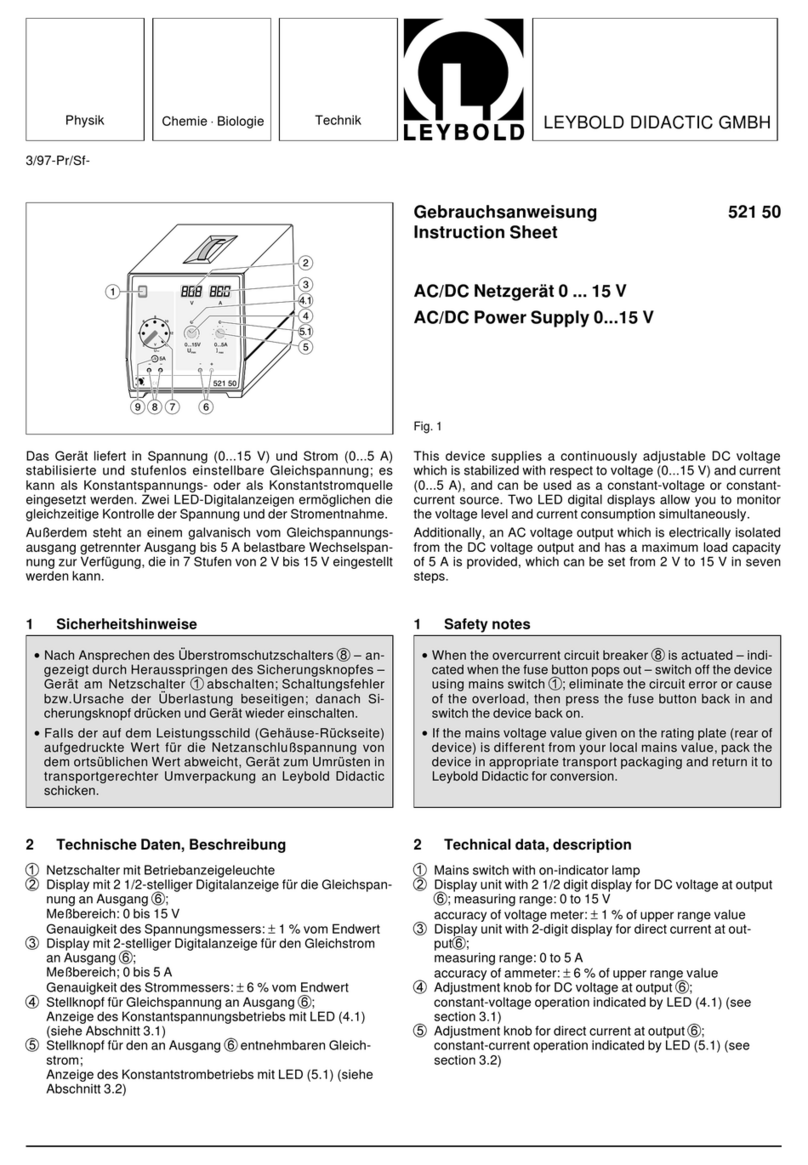
  9. LEYBOLD 666 471 User manual

LEYBOLD 666 471 User manual

Physik Chemie ⋅Biologie Technik LEYBOLD DIDACTIC GMBH
10/95-Ne/Ba-
Gebrauchsanweisung 666 471
Instruction Sheet
Mains socket on CPS-panel for voltage supply of CPS-experiment
apparatus requiring 230 V AC. The socket is switchable using a
bridging plug, TTL-signal, programmable logic control (PLC) and
contact thermometer.
1 Safety notes
2 Description
2.1 Scope of supply
Voltage supply on chemistry panel, consisting of:
1
Main switch
2
Miniature fuse, T 6.3 A
3
4-mm sockets for connecting a bridging plug or the PLC
4
Connection for contact thermometer (666 195)
5
4-mm TTL input (e.g. for connection to the digital output of
a CASSY interface)
6
LED as operating indicator
7
230 V socket for voltage supply of the end unit to be
switched
8
Power lead on rear of chemistry panel
2.2 Technical data
Voltage supply: 230 V/50 Hz
Fuse: miniature fuse T 6.3 A
Relay switching power: max. 1200 VA
Dimensions (overall): 100 x 297 x 115 mm
Weight: 0.7 kg
Netzsteckdose auf CPS-Experimentierplatte zur Spannungsver-
sorgung von CPS-Experimentiergeräten, die 230 V Wechselspan-
nung benötigen. Die Steckdose ist schaltbar durch Brücken-
stecker, TTL-Signal, SPS (Speicherprogrammierbare Steue-
rung) und Kontaktthermometer.
1 Sicherheitshinweise
2 Beschreibung
2.1 Lieferumfang
Spannungsversorgung auf Experimentierplatte, bestehend aus:
1
Hauptschalter
2
Feinsicherung, T 6,3 A
3
4-mm-Buchsen zum Anschluß eines Brückensteckers oder
der SPS
4
Anschluß für Kontaktthermometer (666 195)
5
4-mm-TTL-Eingang (z. B. für Anschluß an digitalen Aus-
gang eines CASSY-Interfaces)
6
Leuchtdiode als Betriebszustandsanzeige
7
230 V-Steckdose zur Spannungsversorgung der zu schal-
tenden Endgeräte
8
Netzkabel auf der Rückseite der Experimentierplatte
2.2 Technische Daten
Spannungsversorgung: 230 V/50 Hz
Sicherung: Feinsicherung T 6,3 A
Schaltleistung des Relais: max. 1200 VA
Abmessungen (gesamt): 100 x 297 x 115mm
Gewicht: 0,7 kg
CPS-Spannungsversorgung, schaltbar
CPS Voltage Supply, Switchable
Fig. 1
Use caution when experimenting with water and aggressive
liquids.
Observe the maximum load capacity of the switching relay.
Do not switch on the main switch until the device has been
completely connected.
Vorsicht beim Experimentieren mit Wasser und aggressiven
Flüssigkeiten.
Maximale Belastbarkeit des Schaltrelais beachten!
Hauptschalter erst einschalten, wenn Gerät vollständig be-
schaltet ist
LEYBOLD DIDACTIC GMBH ⋅Leyboldstrasse 1 ⋅D-50354 Hürth ⋅Phone (02233) 604-0 ⋅Telefax (02233) 604-222 ⋅ Telex 17 223 332 LHPCGN D
©byLeyboldDidacticGmbH, PrintedintheFederalRepublicofGermany
Technical alterations reserved
3 Bedienung
3.1 Montage
CPS-Profilrahmen montieren, dann CPS-Spannungsversor-
gung von der Rückseite des Profilrahmens in die obere Profil-
schiene einführen und nach oben schieben (ca. 1 cm); an-
schließend in die untere Profilschiene einführen und nach un-
ten schieben (ca. 1 cm). Ausbau der CPS-Spannungsversor-
gung aus dem Profilrahmen in umgekehrter Reihenfolge: Nach
oben bis zum Anschlag schieben; dann nach hinten aus der
oberen Profilschiene herausnehmen.
3.2 Inbetriebnahme
Zu versorgendes Endgerät (z. B. Rührmotor oder Heizstab) mit
der Steckdose
7
verbinden. Je nach Art der gewünschten
Steuerung (SPS, TTL oder Kontaktthermometer) die entspre-
chenden Ausgänge mit einer der Eingangsbuchsen
3
,
4
oder
5
verbinden.
Werden die Buchsen
3
mit einem Brückenstecker verbunden,
so bleibt die Steckdose
7
permanent eingeschaltet
Netzkabel
8
auf der Rückseite der CPS-Spannungsversor-
gung mit 230 V Wechselstromanschluß verbinden.
Hauptschalter
1
einschalten, um die schaltbare Spannungs-
versorgung zu aktivieren. Externen Geber (SPS, TTL oder Kon-
taktthermometer) einschalten.
Bei Erreichen des gewünschten Schaltwertes wird durch die
externe Steuerung die Spannungsversorgung der Steckdose
7
und damit das verbundene Endgerät ein- bzw. ausgeschal-
tet.
4 Wechsel der Sicherungen
Zuerst Netzstecker ziehen dann schwarzen Deckel
2
mit einer
kleinen Münze oder mit Schraubendreher entfernen. Hierzu mit
leichtem Druck den Deckel eine halbe Umdrehung nach links
drehen (Bajonettverschluß). Defekte Sicherung gegen intakte
Sicherung austauschen. Deckel wieder aufsetzen und mit einer
halben Umdrehung nach rechts festschrauben.
Nur Sicherungen mit den oben genannten Spezifikationen be-
nutzen.
3Operation
3.1 Montage
Assemble the CPS-panel frame, then insert the CPS-voltage
supply in the top profile rail of the panel frame from the rear and
slide it upwards (approx. 1 cm); next, insert it in thelower profile
rail and slide it downward (approx. 1 cm). Remove the CPS-
voltage supply from the panel frame in reverse order: slide the
panel up until it stops, then remove it from the top profile rail
from the rear.
3.2 Putting into operation
Plug the end unit to be supplied (e.g. stirrer or heating coil) in
socket
7
. Depending on the type of control desired (PLC, TTL
or contact thermometer), connect inputs
3
,
4
or
5
to the
corresponding control outputs.
When sockets
3
are connected using a bridging plug, mains
socket
7
is permanently on.
Connect the power lead
8
on the rear of the CPS-voltage
supply to a 230 V AC outlet.
Switch on main switch
1
to activate the switchable voltage
supply. Switch on the external signal generator (PLC, TTL or
contact thermometer).
When the desired switching value is reached, the external con-
trol unit automatically switches the voltage supply of mains
socket
7
, and thus the connected end unit, on or off.
4 Changing the fuses
First unplug the unit from the mains outlet, then remove the
cover
2
using a small coin or a screwdriver.Press down on the
cover lightly and turn the screw a half-turn to the left (bayonet
connector). Remove the defective fuse and replace it with a
new one. Then close the cover again and latch it by turning it a
half-turn to the right.
Only use fuses which comply with the specifications given above.

Other LEYBOLD Power Supply manuals

LEYBOLD 737 01 User manual

LEYBOLD

LEYBOLD 737 01 User manual

LEYBOLD TURBO.POWER 300 User manual

LEYBOLD

LEYBOLD TURBO.POWER 300 User manual

LEYBOLD 521 50 User manual

LEYBOLD

LEYBOLD 521 50 User manual

LEYBOLD 521 55 User manual

LEYBOLD

LEYBOLD 521 55 User manual

LEYBOLD TURBO.POWER 800 User manual

LEYBOLD

LEYBOLD TURBO.POWER 800 User manual

Popular Power Supply manuals by other brands

Mission Critical NEWMAR Sentinel Installation & operation manual

Mission Critical

Mission Critical NEWMAR Sentinel Installation & operation manual

GE Tetra GEXLPS21 installation guide

GE

GE Tetra GEXLPS21 installation guide

Velleman K7200 manual

Velleman

Velleman K7200 manual

HP StorageWorks 1000 - Modular Smart Array Programming guide

HP

HP StorageWorks 1000 - Modular Smart Array Programming guide

SEW-Eurodrive MOVIDRIVE MDR60A System manual

SEW-Eurodrive

SEW-Eurodrive MOVIDRIVE MDR60A System manual

Genie GPR816/12R quick start guide

Genie

Genie GPR816/12R quick start guide

Jetter JetMove 3000 user manual

Jetter

Jetter JetMove 3000 user manual

Beckhoff PS2001-2440-0000 Documentation

Beckhoff

Beckhoff PS2001-2440-0000 Documentation

Phoenix Contact FB-DP Series Configuration and setup

Phoenix Contact

Phoenix Contact FB-DP Series Configuration and setup

Extron electronics PS 124 installation manual

Extron electronics

Extron electronics PS 124 installation manual

Alpha Technologies Cordex Installation & operation manual

Alpha Technologies

Alpha Technologies Cordex Installation & operation manual

Rath 2500-PWR24U Installation & Specifications Manual

Rath

Rath 2500-PWR24U Installation & Specifications Manual

SLAT AES 28V/8A operating instructions

SLAT

SLAT AES 28V/8A operating instructions

Pace MBT 201A Operation & maintenance manual

Pace

Pace MBT 201A Operation & maintenance manual

Mounting Solutions PDV-6S manual

Mounting Solutions

Mounting Solutions PDV-6S manual

Hama Universal Netbook Power Supply Operating	 instruction

Hama

Hama Universal Netbook Power Supply Operating instruction

Keysight Technologies RP7900 Series Operating and service guide

Keysight Technologies

Keysight Technologies RP7900 Series Operating and service guide

TDK-Lambda CPFE500F-28 Handbook

TDK-Lambda

TDK-Lambda CPFE500F-28 Handbook

manuals.online logo
manuals.online logoBrands
  • About & Mission
  • Contact us
  • Privacy Policy
  • Terms and Conditions

Copyright 2025 Manuals.Online. All Rights Reserved.