LEYRO LDT 2000 User manual

1
LDT 2000
PRECISION THERMOMETER
MANUAL

Leyro Instruments® doesn’t accept warranty and liability claims
neither upon this publication nor in case of improper treatment of the
described products.
The document may contain technical inaccuracies and typographical
errors. The content will be revised on a regular basis. These changes
will be implemented in later versions. The described products can be
improved and changed at any time without prior notice.
© Copyright Leyro Instruments ®
All rights reserved.

TABLE OF CONTENTS
1. GENERAL
1.1. Symbol assertion
1.2. General safety instructions
2. PRODUCT DESCRIPTION
2.1 Features
3. OPERATION
3.1 Preparation to work
3.2 Power-on sequence
3.3 Stand- alone benchtop operation (without PC)
3.4 Operation with PC and Thermometer Utility software
3.5 Operation with PC and custom software
3.6 Internal battery
3.7 Calibration period
3.8 Calibration period
4 ADVANCED USER INFORMATION
4.1 Block diagram
4.2 Probes
4.3 Extender
4.4 Resistance calibration
4.5Coefcients
4.6 PC interface
5. TYPICAL PERFORMANCE OF THE LDT 2000 THERMOMETER
6. THERMOMETER UTILITY SOFTWARE
6.1 Program at a glance
6.1.1 Installation and requirements
6.1.2 Main window overview
6.2 Viewing and setting up the chart
6.3 Recording measured data
6.3.1 Storing and using recorded data
6.4Conguration
6.5 Calibration
6.6 USB Drivers

7. COMMUNICATION PROTOCOL
7.1 Communication interfaces
7.2 SCPI protocol
7.2.1 Syntax
7.2.2 Commands
7.2.3 Command termination character
7.2.4 Structure of commands
7.2.5 Query
7.2.6 Parameters
7.2.7 Special commands
7.2.8 Special characters
7.2.9 Commands’ execution
7.2.10 Default commands
7.3 Status registers
7.3.1 STB status register
7.3.2 Events register (ESR)
7.3.3 Operation register (OPER)
7.3.4 Reliability register (QUES)
7.3.5 Errors queue
7.3.6 Mask registers
7.4 Commands’ parameters
7.4.1 Binary <boolean>
7.4.2 Integer number <int>
7.4.3 Floating-point number <double>
7.4.4 String
7.4.5 Channels’ list
7.5 Special commands
7.6 Thermometer commands catalogue
7.6.1 Tree of commands
7.6.2 Measurement commands
7.6.2.1 :INITiate
7.6.2.2 :CONFigure

7.6.2.3 :CONFigure?
7.6.2.4 Result readout commands :FETCh? and :READ?
7.6.2.5 :MEASure?
7.6.3 :UNIT – measurement’s units handling
7.6.4:INPut–measurementcircuitconguration
7.6.4.1:FILTer–congurationoflinefrequencylter
7.6.5:SENSe–congurationofmeasurement’sparameters
7.6.5.1 :AVERage – measurement averaging
7.6.5.2:OVERow–probe’stemperaturerangeexceedingag
7.6.6 :CALibration – calibration commands
7.6.6.1 :ALL – autocalibration
7.6.6.2 :SECure – calibration unlocking
7.6.6.3 :RESistance – resistance measurement calibration
7.6.6.4 : CHannel 1 and :CHannel 2 – probes’ calibration
7.6.7 :MEMory – internal EEPROM memory handling
7.6.8 :DISPlay – display operations
7.6.9 :STATus – status registers handling
7.6.9.1 :OPERation – operation register
7.6.9.2 QUEStionable – reliability register
7.6.9.3 :PRESet
7.6.10 :SYSTem
7.6.10.1 :ERRor – reading errors
7.6.10.2 :DATE <year, month, day>
7.6:10:3 :TIME <hour, minute, second>
7.7Notiederrors
7.7.1 Device errors
7.7.2 SCPI errors

6
The manual is a part of the scope of supply and serves to ensure proper handling and
optimum functioning of the instrument.
LEYRO Instruments doesn’t accept warranty and liability claims neither upon this publica-
tion nor in case of improper treatment of the described products.
For this reason, the manual must be read before start-up.
In addition, the manual is for all personnel who require knowledge concerning transport,
setup, operation, maintenance and repair.
The manual must not be used for the purpose of competition without a written consent from
Leyro Instrume®nts and must also not be forwarded to third
parties. Copies for personal use are permitted.
1. GENERAL
1.1 Symbol assertion
This symbol indicates a safety instruction.
These safety instructions should always be followed carefully.
By not following these instructions injuries of persons or material damage could
happen.
This symbol indicates a note.
These notes should be observed to achieve optimum functioning of the equip-
ment.
1.2 General safety Instructions
The LDT 2000 temperature meter is a device designed for laboratory, indoor
use. It is powered from 85 to 250V line, therefore the user should work with
respect to all precautions related to operating with mains powered equipment.
The mains socket should always have working grounding path!
The LDT 2000 is a laboratory- grade precision digital thermometer which uses Pt-100 pla-
tinum resistors as temperature sensors. The device provides two measuring channels. The
range of measured temperatures is from -150°C to +350°C for option 0x, and from -150°C
to +850°C for option 1x (measuring circuit limitation, probe may have its own limitations).
A characterictic feature is high resolution (0,001°C) and high acuraccy of temperature
measurement (±0,007°C with NIST-traceable calibrated probe – on demand). The LDT
2000 digital thermometer uses advanced internal autocalibration circuits that minimize
effects of electronic components aging (Vishay ultrastable resistors technology). Thermal
EMF induced error is eliminated on the whole path between thermometer and the probe by
2. PRODUCT DESCRIPTION

7
2.1 Features
•Pt-100resistorsastemperaturesensors
•twomeasurementchannels
•highresolution(0,001°C)
•temperaturemeasurementaccuracyupto±0.007°C(specialon-demandversion)
•internalautocalibrationcircuitry
•easytooperate
•enclosuremadeofdurablematerials
•ThermometerUtilitysoftwareinpriceoftheproduct-conguration,acquisitionofmeasu-
rements
•largedisplay
•calibrationdataprotectedbyatriplememorywritesystem
•possibilityofintroductionofuser’sCallendar-VanDusencoefcients
•temperaturedisplayedin°C,°F,K
•displayofadditionalparameter:gradient,resistance,temperaturedifference
•USBandRS-232interfaces
the means of Current Reversal technique. The autocalibration sequence is a background
task performed continuously. The LDT 2000 has been designed to make operating as
simpleaspossible.Anadvancedcongurationanddataacquisitionoptionsareavailable
by the means of PC interface and suitable PC software. A large illuminated LCD display is
capable of indicating several parameters simultanously.
Temperature measurement
range
Resolution
Acuraccy
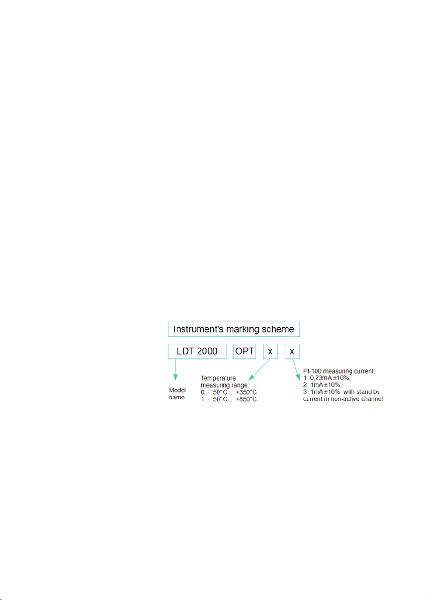
-150°C...+350°C(0…230,0000Ω)-OPT0x,0x,0x
-150°C...+850°C(0…450,0000Ω)-OPT1x,1x,1x
0,001°C(1mK),noise≤±1mK-OPT01,02,03
0,001°C(1mK),noise≤±3mK-OPT11,12,13
±0,007°C in the range 0°C … 100°C ; ±0,00014*(T-
50°C) beyond (with NIST-traceable calibrated probe
-on demand)
±0,020°C in the range 0°C … 100°C ; ±0,0004*(T-50-
°C) beyond (with probe calibrated by Leyro Instru-
ments)
±0,080°C in the range; ±0,0016*(T-50°C) beyond
(with uncalibrated probe)

8
Pt-100 measurement current
Pt-100 self heating power
Supply
Power consumption
Fuses
Connectors
RS-232 parameters
USB standard
Communication protocol
Temperature range
Dimension
Weight
LDT 2000 OPT x1, x1: 0,23mA ±10%;
LDT 2000 OPT x2, x2: 1mA ±10%;
LDT 2000 OPT x3, x3: 1mA ±10% with stand by
current in non-active channel
LDT2000OPTx1,x1:5,8μWfor0°C
LDT2000OPTx2,x2:101μWfor0°C
LDT2000OPTx3,x3:101μWfor0°C
85-250VAC, 45...65 Hz
8VA max. 4VA typically
2xSLOW1A250V;5x20mm
•Supply230V–IECC14
•USBBconnector–USBinterface
•DB9-RS-232interface
ABaud rate: 9600; data bits: 8; parity:no; stop bits:1
USB 2.0
SCPI compatible
storage:-10°C...+60 °C;
usage: 10°C...40 °C, non-condensing
271 x 280 x 102,6 mm
ca. 1,5 kg
3. OPERATION
3.1 Safety
The LDT 2000 temperature meter is a device designed for laboratory, indoor use. It is
powered from 85 to 250V line, therefore the user should work with respect to all precau-
tions related to operating with mains powered equipment. The mains socket should always
have working grounding path!
3.2 Preparation to work
1. Connect one or two (as needed) probes to the sockets on the thermometer’s front panel.
Pleasekeepinmindthateachchannelhasitsowncalibrationcoefcientsandprobe’s
plug must be placed in proper, signed socket. A mistake will result in wrong temperature
readings
2. Connect the instrument to the power line
3.TurnontheinstrumentbypressingPOWERswitch
4. Read the messages displayed by the instrument (chapter 3.3)
5.Waituntilselfcalibrationsequencereaches100%
6. The thermometer is now ready to stand- alone operation

9
Following steps are required only if operation with Thermometer Utility
software is required
7. Please install USB driver and Thermometer Utility software prior to the
rstthermometerconnection
8. Connect the thermometer to the PC computer using USB or RS-232 cable
9. Run Thermometer Utility software
10. Press scan button to get serial number of connected instrument
11. Press connect button to comumicate the instrument with PC
12. Follow appendix B to take advantage of the Thermometer Utility software
3.3 Power-on sequence
After turning on, the instrument displays sequence of three important screens.
The whole sequence lasts about 40s to 120s depending on used averaging (N=1 to 10).
The screens are presented in order of apperance.
Therstscreen(g1)showsgeneralinformationabouttheinstrument:
Name of the manufacturer;
Model name;
Firmware version;
Self calibration progress;
Secondscreen(g2)showsinformationaboutprobeconnectedtochannel
CH1:
Name typed during calibration;
Minimum alllowed temperature; Exceeding limit information (not in this example);
Maximum alllowed temperature; Exceeding limit information (not in this example);
Self calibration progress;
Thirdscreen(g3)showsinformationaboutprobeconnectedtochannelCH2:
Name typed during calibration;
Minimum alllowed temperature; Exceeding limit information (true in this example);
Maximum alllowed temperature; Exceeding limit information (true in this example);
Self calibration progress;

10
Whentheselfcalibrationcounterreaches100%thethermometerentersitsstandardmea-
suringmodeandisreadytouse(g4).Theblinking“+”signnearT1meansthatprobein
channel 1 is beeing measured at the moment.
3.4 Stand- alone benchtop operation (without PC)
The LDT 2000 has been designed to make operating as simple as possible.
Follow steps from chapter 3.2.
3.5 Operation with PC and Thermometer Utility software
The Thermometer Utility software was developed for easy intuitive data acquisition from
theLDT2000thermometer.ThesoftwareisavailableforMicrosoftWindowsOperating
Systems.
The software supports:
1. Monitoring measured parameters in time domain using adjustable scale display
2. Data acqiusiton and recording. Advanced controlls allow many options of starting /
nishingofrecording.
3.Conguringthethermometerforstand-aloneoperation.
4.Recalibrationofresistancemeasuringcircuitry,readingandwritingofthecoefcient’s
memory.
TheuserwillnddetaileddescriptionofallfunctionsandfeaturesunderinAppendixB
Thermometer Utility software.
3.6 Operation with PC and custom software
User’scustomsoftwareorsimpleTerminalprogramscanbeusedtocongure/readdata
from the thermometer. Appendix C contains detailed description of the communication
protocol.

11
3.7 Internal battery
Inside the meter’s enclosure there is a battery used for memory backup. The memory
stores: internal clock, data, display settings. Estimated lifetime of the battery is 5 years. In
case of wrong time or data display, it might be necessary to replace this battery. Lithium
battery 3V type CR 2032.
3.8 Calibration period
The manufacturer suggest 24 months calibration interval for the LDT 2000 device.
The probes should be calibrated:
– every 24 months if the working temperature is T < 200 °C
–every12monthsiftheworkingtemperatureisT≥200°C
4. ADVANCED USER INFORMATION
4.1 Block diagram
The LDT 2000 thermometer is a microprocessor -based meter which accurately measu-
res probe’s resistance and calculates temperature based on the Callendar– Van Dusen
equation. Modern high quality components have been used to ensure high precision and
reliability.Blockdiagramofthedeviceisshownong5.
4.2 Probes
ThethermometersupportstwoPt-100probes.FourterminalKelvinsensingtechniqueis
used to provide highest level of accuracy. The cable of the probe is shielded to reject most
of electromagnetic interference that could affect the measurement. Internal wiring of the
probeisshownong6.

12
Important: Metal part of the probe is grounded in most types of probes.
TheprobesareprovidedwithuniqueCallendar–VanDusencoefcients.
Thedeviceprovidestwomeasuringchannels.Whenusingtwoprobestheactivechannel
is switched periodically with period of about 1,5s (or longer when averaging of samples is
used).
4.3 Extender
Theprobe’scablelengthmaybeinsuftcientinsomecases.Theusercanincreasethe
cable length by using an extender having the maximum length of 8m without loosing accu-
racy.Highquality4wire,highdensityshieldcableshouldbeused.Teon(PTFE)insulated
cable is preferred. Using long extender in industrial environment with very high electromag-
netic interferences level can increase the measurement noise.
4.4 Resistance calibration
In case of performing resistance calibration procedure or using the LDT 2000 as a pre-
cisionohmmetertheusershouldfollowconnectionschemeshownong6andusethe
Amphenol C091-T3400-001 connector for connecting external measured resistor. It is ne-
cessarytoshorttwomiddlepinsoftheconnectortoprovidethe„probedetectloop”.Ifthe
user change accidentally U1 with U2 or I1 with I2 the meter will display negative reading
eg.-100.0000Ω.Thismustbecorrectedpriorcalibrationotherwiseanerrorwilloccur.
Important: During internal resistor calibration procedure, external standard
resistor MUST be connected to CH1.

13
4.5 Coefcients
ThethermometerusesCallendar–VanDusencoefcientstocalculateexacttemperature
oftheprobe.Eachprobehasuniquesetofcoefcientsdevelopedwhilecalibration.To
achiveproperreadings,theseuniquecoefcientsshouldbestoredinthethermometer’s
memory.Inordertodoso,followChapter5instructions.Ifnocoefcientsaretyped,the
thermometer uses default values presented in Tab2.
If the resistance value is set to be displayed, the resistance reading is always a raw data –
data without any mathematical computing.
4.6 PC interface
The meter supports USB 2.0 and RS-232 interfaces. The protocol is compatible with SCPI
language. The examples of the most common commands are listed below.
All details connected with SCPI communication are described in appendix B.
AsuitableMicrosoftWindowsUSBdriverle:„STM_VCP_DRIVER.zip”canalsobedown-
loaded from the web site listed above.
The most frequently used commands are listed below (this symbol // marks the comment):
*idn?$00 //identify command, response will be eg.
„Leyro Instruments, LDT 2000 OPT02,
0413,1.1”
:syst:date?; time?$00 //date and hour question
:syst:date 2013,04,04; time 23,22,00$00 //date and hour setting
:disp:menu:name res$00 //enabling resistance display
:disp:menu:name grad$00 //enabling gradient display
:init:cont off; cont?$00 //enabling sequential results sending
:meas:temp:val? (@1)$00 //send temperature measured in CH1
:sens:aver:coun 4$00 //enable averaging of 4 samples
:cal:sec:stat1,2804$00;:cal:sec:stat?$00 //enablingcalibration,response:„ON”
:cal:res:val 100.0034$00 //internal resistor calibration using
standard resistor connected to CH1
(value100.0034Ω)

14
5. TYPICAL PERFORMANCE OF THE THERMOMETER

15

16

17

18
6. THERMOMETER UTILITY SOFTWARE
6.1 Program at a glance
Thermometer Utility software allows to use LDT 2000 thermometer with PC computer. It
allowstouseallbenetsofdataacquisitionandremotecongurationofthethermometer.
ThesoftwarecanbeeasilyinstalledonanyMSWindowsOperatingSystemandrequires
RS232 (COM) or USB port to connect.
6.1.1 Installation and requirements
Tostarttheinstallation,run“setup.exe”leandconrmtodeploytheprogram.Afterquick
setup,utilityrunsforthersttime.Lateritwillbeavailablefromdesktopshortcut(g13).
g13:ThermometerUtilityicon
Thermometer Utility was developed on .NET Framework and requires at least 2.0 version
of this platform to work. Therefore, in case when it is not available on destination computer,
itcanbeinstalledbyrunning“dotnetfx2.exe”le.
Most up-to-date version of .NET Framework should be downloadable from Microsoft Down-
load Centre on the Internet.

19
6.1.2 Main window overview
ThermometerUtilitymainwindowconsistsoffewparts,shownandmarkedong14.
Tool bar on top, allows to select and to connect with chosen thermometer. During startup,
the program searches for compatible devices on available serial communication ports.
Afterwards, the amount of devices found is displayed on status bar (bottom part of the win-
dow). This allows to use several separate thermometers with several Thermometer Utility
instances at one PC at one time.
Desiredthermometercanbechosenbyexpandingcombo-listnextto“CONNECT”button
and selecting device’s serial number. After pressing the mentioned button, communication
with thermometer will initialize and other functions will activate.
Below the toolbar, resides a panel of currently measured levels: temperature, gradient and
resistance (for plugged and used probes: CH1, CH2). These levels can be reviewed in
time,onthe“Temporalchart”tab,orrecordedfrom“Recorddata”tab.Bothsectionsofthe
program are described in separate chapters.
Incasewhenthethermometerwaspluggedintoportduringprogram’swork,press“SCAN”
to refresh the list of available devices. It is possible however, while the program is discon-
nected from any device.

20
6.2 Viewing and setting up the chart
Chart component can display function curves of two of possible values at a
time:
•TEMP1orTEMP2–temperaturevalues;
•GRAD1orGRAD2–gradients;
•RES1orRES2–resistancevalues.
•DIFF-differenceintemperaturesT1-T2
Asitisshownong15,secondaryfunctioncanbeturnedoff,bychoosing“None”from
selection list.
Subsequent measured values are being appended at the end of chart, therefore since the
startofcollection,it“grows”totheright.Thechartcanstoreupto24hoursofsamples,and
after that time, the chart stops receiving further data.
The chart however can be reset any time by pressing Clear chart button, located in the
lower-right part of the panel.
Therearetwosetsofelds,whichrelatetoprimaryandsecondaryfunctionshownonthe
chart(g16).Firstisanexpandablelist,wheredesiredvaluecanbeselected.Nearthe
list, a square button is available, allowing to change the color of corresponding curve. Clic-
kingthiseldwillshowastandarddialogbox,wherethenewcolorcanbechosen.
Table of contents