- 2 -
1. Specification
Note:
1. All data are based on the following conditions:
- Cooling Temperature : Indoor 26.7°C(80°F) DB / 19.4°C(66.9°F) WB
Outdoor 35°C(95°F) DB / 23.9°C(75°F) WB
- Heating Temperature : Indoor 21.1°C(70°F) DB / 15.6°C(60.1°F) WB
Outdoor 8.3°C(46.9°F) DB / 6.1°C(43°F) WB
- Piping Length : Interconnected Pipe Length = 5 m (16.4 ft)
- Difference Limit of Elevation (Outdoor ~ Indoor Unit) is Zero.
2.
Wiring cable size must comply with the applicable local and national code.
3. Due to our policy of innovation some specifications may be changed without
notification.
4. Sound Level Values are measured at Anechoic chamber.
Therefore, these values can be increased(maximum 3dB(A)) owing to ambi-
ent conditions during opration.
** : The unit could be operated on the followig temperature range only when Low
Ambient Kit installed.
- Cooling : Outdoor Temperature -20°C(-4°F) ~ -10°C(14°F) DB
Model Name
A2UW18GFH0
[LMU180HHV]
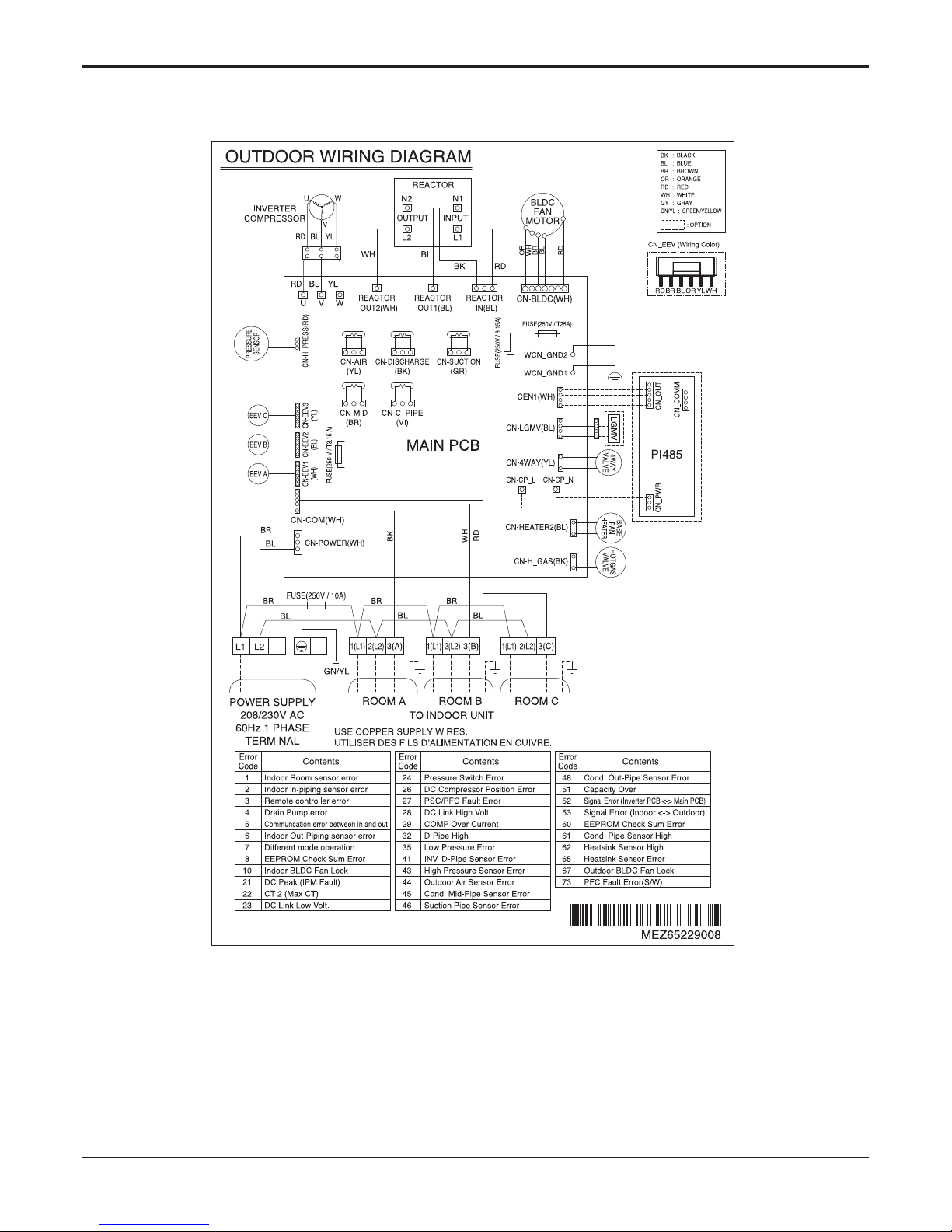
A3UW24GFH0
[LMU240HHV]
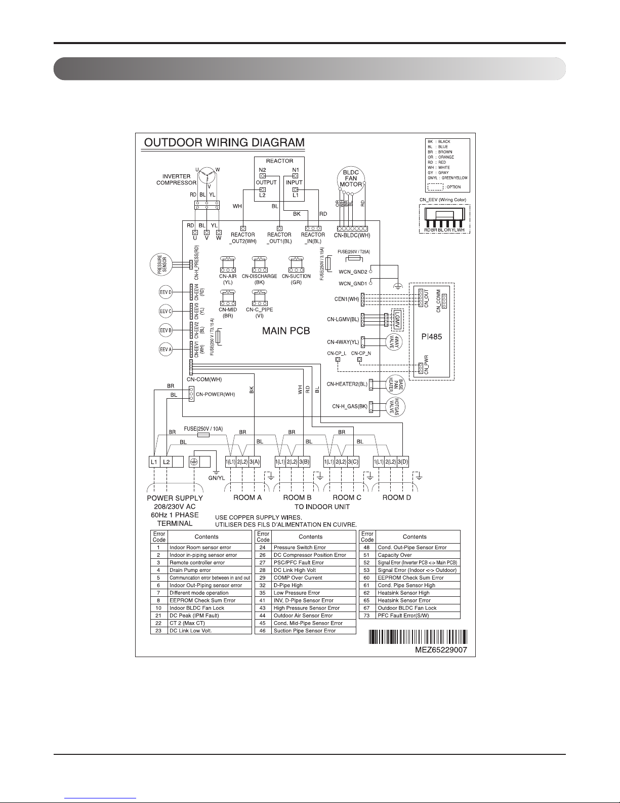
A4UW30GFH0
[LMU300HHV]
Capacity
Nominal Btu/h Class
18,000 24,000 30,000
Cooling Min~Rated~Max Btu/h
8400~18000~19980 8400~24000~30000 8400~28400~34080
Heating Min~Rated~Max Btu/h
10248~22000~24000 10248~26000~31200 10248~28600~41600
Power Input Cooling Min~Rated~Max kW
0.87~1.33~1.92 0.93~1.78~2.63 0.94~2.27~3.47
Heating Min~Rated~Max kW
1.24~2.20~3.29 1.25~2.12~3.47 1.29~2.32~3.55
EER/COP Non Ducted -
13.5/2.9 13.5/3.6 12.5/3.6
SEER/HSPF
Non Ducted -
21.0/10.0 21.0/10.7 20.0 / 11.0
Mixed -
19.25/9.5 19.0/9.85 18.75/10.25
Ducted -
17.5/9.0 17.0/9.0 17.5/9.5
Power Supply V, Ø, Hz
208/230, 1, 60 208/230, 1, 60 208/230, 1, 60
Running Current Cooling Min~Rated~Max A
4.1~6.1~8.7 4.2~7.8~11.9 4.0~10.2~16.7
Heating Min~Rated~Max A
5.6~9.8~14.9 4.8~9.9~14.9 4.2~10.9~15.9
Starting Current Cooling Max A
- - -
Heating Max A
- - -
Wiring Connections
Power Supply Cable (Included Earth) No. x AWG
3C x 12 3C x 12 3C x 12
Power and Communication Cable
(Included Earth) Outdoor ~ BD Unit No. x AWG
- - -
Combination
Sum of Indoor Units Capacity Max kBth/h
24 33 40
Number of Indoor Units Max EA
2 3 4
Number of BD Units Max EA
- - -
Casing Color -
Warm Gray Warm Gray Warm Gray
Dimensions W x H x D mm
950 x 834 x 330 950 x 834 x 330 950 x 834 x 330
W x H x D inch
37-13/32 x 32-27/32 x 13 37-13/32 x 32-27/32 x 13 37-13/32 x 32-27/32 x 13
New Weight kg(lbs)
67 (147.7) 69 (152.1) 69 (152.1)
Compressor
Type -
Twin Rotary Twin Rotary Twin Rotary
Model Model x No.
GJT325M X 1 GJT325M X 1 GJT325M X 1
Motor Type -
BLDC BLDC BLDC
Motor Output W x No.
- - -
Refrigerant
Type -
R410A R410A R410A
Precharged Amount g (oz)
2,800 (98.8) 3,200 (112.8) 3,200 (112.8)
Chargeless-Pipe Length m (ft)
15 (49.2) 22.5 (73.8) 30 (98.4)
Additional Charging Volume g/m (oz/ft)
20 (0.22) 20 (0.22) 20 (0.22)
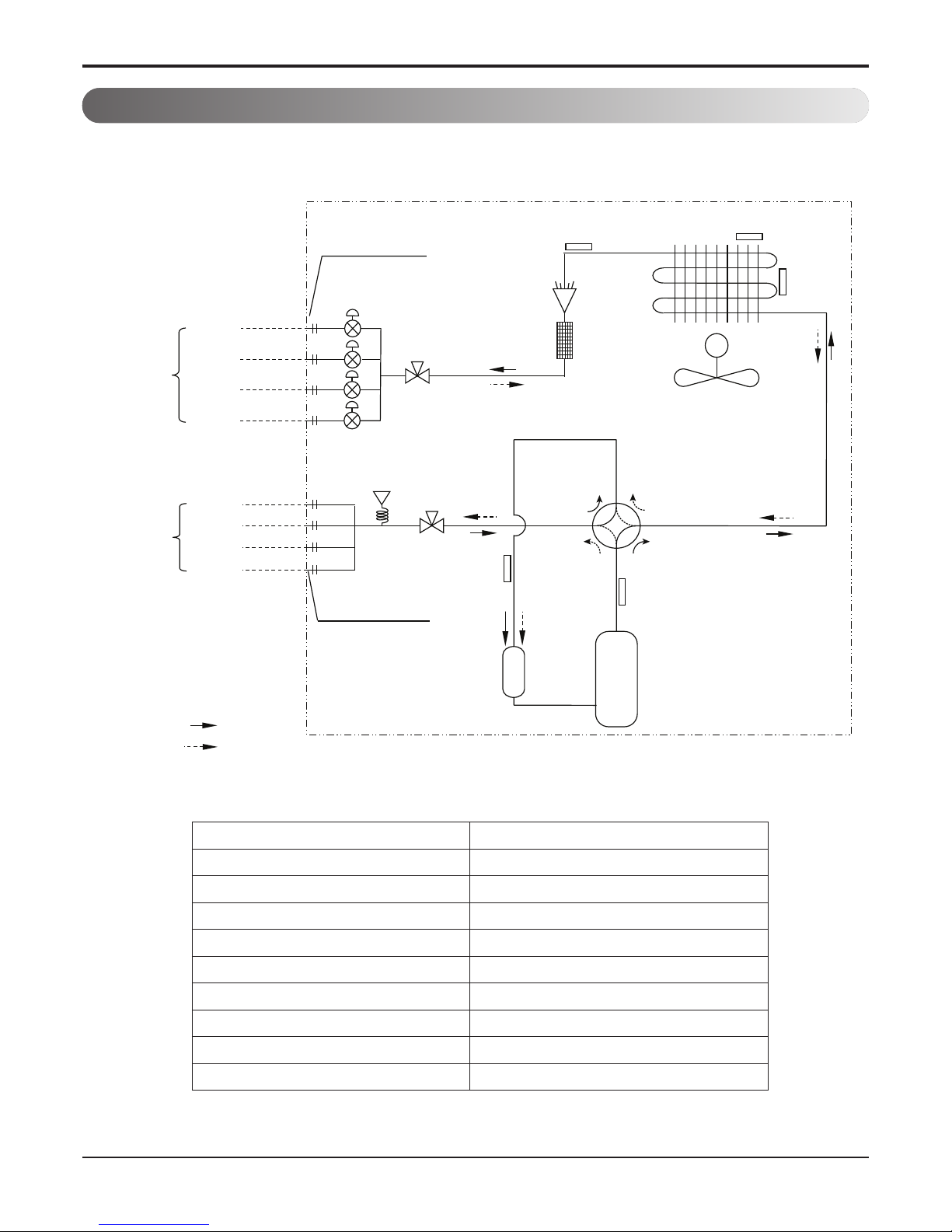
contorl -
Electronic Expansion Valve Electronic Expansion Valve Electronic Expansion Valve
Refrigerant Oil Type -
FVC68D FVC68D FVC68D
Charged volume cc x No.
950 x 1 950 x 1 950 x 1
Heat Exchanger (Row x Column x Fins per inch) x No. -
(3 x 38 x 16) x 1 (3 x 38 x 16) x 1 (3 x 38 x 16) x 1
Fan Type -
Propeller Propeller Propeller
Air Flow Rate m3/min(ft3/min) x No.
65 (2,295) 65 (2,295) 65 (2,295)
Fan Motor Type -
BLDC BLDC BLDC
Output W x No.
124.2 x 1 124.2 x 1 124.2 x 1
Sound Pressure Level Cooling Rated dB(A)
50 52 52
Heating Rated dB(A)
54 55 55
Sound Power Level Cooling Rated dB(A)
- - -
Piping Connections Liquid Outer Dia. mm(inch)
Ø6.35 (1/4) Ø6.35 (1/4) Ø6.35 (1/4)
Gas Outer Dia. mm(inch)
Ø9.52 (3/8) Ø9.52 (3/8) Ø9.52 (3/8)
Piping Length
Total Piping Max. m (ft)
50 (164) 75 (246.1) 75 (246.1)
Main Piping Max. m (ft)
- - -
Total Branch Piping Max. m (ft)
- - -
Each Branch Piping Max. m (ft)
25 (82.0) 25 (82.0) 25 (82.0)
Maximum Height
Difference
Outdoor Unit ~ Indoor Unit Max. m (ft)
15 (49.2) 15 (49.2) 15 (49.2)
Indoor Unit ~ Indoor Unit Max. m (ft)
7.5 (24.6) 7.5 (24.6) 7.5 (24.6)
BD Unit ~ Indoor Unit Max. m (ft)
- - -
Operation Range
(Outdoor Temperature)
Cooling Min. ~ Max. ℃ DB(℉ DB)
-20(-4)** ~ 48(118) -20(-4)** ~ 48(118) -20(-4)** ~ 48(118)
Heating Min. ~ Max. ℃ DB(℉ DB)
-25 (-13) ~ 24 (75) -25 (-13) ~ 24 (75) -25 (-13) ~ 24 (75)


 null")