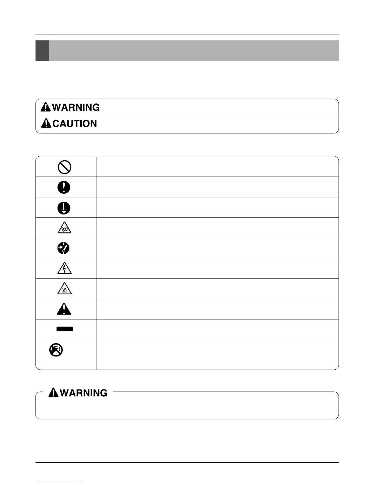
LG Multi V CRUN Series User manual

System SERVICE MANUAL
System
Heat Pump Air Conditioner
SERVICE MANUAL
LG
MODELS: CRUN/CRNN Series
website http://www.lgservice.com
e-mail http://www.lgeservice.com/techsup.html
CAUTION
• BEFORE SERVICING THE UNIT, READ THE SAFETY
PRECAUTIONS IN THIS MANUAL.
• ONLY FOR AUTHORIZED SERVICE PERSONNEL.

2
Air Conditioner Service Manual
TABLE OF CONTENTS
Model Name Namerclature...........................................................................3
Model Names.................................................................................................4
Safety Precautions .......................................................................................5
Indoor Units.............................................................................................9
Ceiling Mounted Cassette Type (1 way)................................................10
Ceiling Mounted Cassette Type (4 way)................................................20
Ceiling Mounted Duct Type (High static)..............................................36
Ceiling Mounted Duct Type (Low static)...............................................48
Convertible Type.....................................................................................58
Wall Mounted Type..................................................................................77
Art Cool Type (Mirror).............................................................................93
Art Cool Type.........................................................................................111
Art Cool Type (Wide).............................................................................127
Flor Standing Type................................................................................144
Outdoor Units.....................................................................................154
Control Devices and Functions...........................................................182
Trouble Shooting Guide .......................................................................209
Appendix................................................................................................243

Model Name Nomenclature
Service Manual 3
CRN N 607 ASR 0
Serial Number
Combinations of functions
A: Basic Function
Art Cool Type Panel Color
B: Blue, C: Cherry, D: Wood, M: Metal
N: Walnut, R: Mirror, W: White, G: Gold
Chassis Name
Electrical Ratings
1:1ø, 100V~115V, 60Hz, 2: 1ø, 220V~240V, 60Hz
6: 1ø, 220V~240V, 50Hz, 7: 1ø, 100V~115V, 50Hz
Total Cooling Capacity in Btu/h unit
Ex) 5,000 Btu/h ➞‘05’ , 18,000 Btu/h ➞‘18’
Combination of Inverter Type and
Cooling Only or Heat Pump or Heat Recovery
N: AC Inverter and H/P, V: AC Inverter and C/O
Indicates that this is
using the R-407C. System indoor unit
CRU N 8100 T 0
Air Discharge Type
S: Side discharge
T: Top discharge
Serial Number
Electrical Ratings
8: 3ø, 380V~415V, 50Hz, 9: 3ø, 380V~415V, 60Hz
A: 3ø 220V, 50Hz, B: 3ø, 220V, 60Hz
C: 3ø, 440V~460V, 50Hz, D: 3ø, 440V~460V, 60Hz
Total Cooling Capacity in Horse Power(Hp) unit
Ex) 4.5 Hp ➞‘45’ , 10 Hp ➞‘100’
Combination of Inverter Type and
Cooling Only or Heat Pump or Heat Recovery
N: AC Inverter and H/P, V: AC Inverter and C/O
Indicates that this is System outdoor unit
using the R-407C.
Note: Suffix - Look: Wall Mounted Type
- Panel: Ceiling Mounted Cassette Type
Indoor Unit
Outdoor Unit

4
Model Names
Series Model name Power
Supply
Inverter Series
(Heat Pump)
4.5
(44,000)
Capacity, Hp(Btu/h) 10
(95,500)
CRUN
458S0 CRUN
1008T0 3ø, 4W,380V~415V,
50Hz
Category Type Chassis
Name
Model Name
Capacity, kW(Btu/h)
Wall
Mounted
Type General SR
ST
2.1
(7,000)
CRNN
076SRA0
-
2.6
(9,000)
CRNN
096SRA0
-
3.5
(12,000)
CRNN
126SRA0
-
5.3
(18,000)
-
CRNN
186STA0
7.0
(24,000)
-
-
8.2
(28,000)
-
-
10.6
(36,000)
-
-
12.3
(42,000)
-
-
14.1
(48,000)
-
-
Art Cool
Mirror SU
SP
CRNN
076SU*0
-
CRNN
096SU*0 CRNN
126SU*0 -
-
-
-
-
-
-
-
-
-
-
-
Art
Cool CRNN
096SP*0 CRNN
126SP*0
SV -CRNN
186SV*0
CRNN
126SV*0 -----
Wide -
Ceiling
Cassette
1 Way TC CRNN
076TCA0 CRNN
096TCA0 CRNN
126TCA0 ------
TE -CRNN
186TEA0 -----
4 Way -CRNN
126TEA0
TD --
CRNN
246TDA0
-- CRNN
286TDA0 CRNN
366TDA0 CRNN
426TDA0 CRNN
486TDA0
Ceiling
& Floor Convertible VB -CRNN
186VBA0 CRNN
246VBA0 ------
Ceiling
Concealed
Duct
High
Static
BH
BG
BE
BN
Low
Static BJ
-CRNN
186BHA0 CRNN
246BHA0
--
--- - CRNN
286BGA0 CRNN
366BGA0
----
--
CRNN
426BGA0
CRNN
486BEA0
---- ----
CRNN
076BNG0 --- -----
-CRNN
096BJG0 CRNN
126BJG0 ------
CAA
CBA
CCA
CDA
With
Case
CRNN
076CAA0 --------
CRNN
096CBA0 CRNN
126CBA0 CRNN
186CCA0 CRNN
246CDA0
---- --
Floor
Standing
Indoor Unit
Outdoor Unit

Safety Precautions
Service Manual 5
Safety Precautions
To prevent indury to the user or other people and property damage the following instructions must be followed.
■Incorrect operation due to ignoring instruction will cause harm or damage. The seriousness is classified by the
following indications.
■Meanings of symbols used in this manual are as shown below.
This symbol indicates the possibility of death or serious injury.
This symbol indicates the possibility of injury or damage to properties only.
Carefully read the labels affixed to the main unit.
Be sure not to do.
Be sure to follow the instruction.
This symbol indicates a part which must be grounded.
This symbol indicates that caution should be taken with rotating parts.
(This symbol is displayed on the main unit label.) <Color: Tellow>
This symbol indicates that the main switch must be turned off before service.
(This symbol is displayed on the main unit label.) <Color: Blue>
This symbol alerts you to the risk of electric shock.
(This symbol is displayed on the main unit label.) <Color: Yellow>
This symbol alerts you to the risk of hot surface.
(This symbol is displayed on the main unit label.) <Color: Yellow>
This symbol alerts you to hazards that could cause harmto the air conditioner.
NOTICE
This symbol indicates special notes.
ELV
Pay attention to electric shock.
And at servicing, please shut down the power supply for both of Indoor and Outdoor
Unit.

6Indoor Unit
Safety Precautions
Use the specified cables for wiring. Make the
connections securely so that the outside force
of the cable is not applied to the terminals.
- Inadequate connection and fastening may gen-
erate heat and cause a fire.
Always use accessories specified by LG
Electronics.
- Ask an authorized technician to install the
accessories. Improper installation by the user
may result in water leakage, electric shock, or
fire.
Cautions before installation
Never repair the unit. If the air conditioner
must be repaired, consult the dealer.
- If the unit is repaired improperly, water leakage,
electric shock, or fire may result.
Do not touch the heat exchanger fins.
- Improper handling may result in injury.
If refrigerant gas leaks during service work,
ventilate the room.
- If the refrigerant gas comes into contact with a
flame, poisonous gases will be released.
Have all electric work done by a licensed
electrician according to "Electric Facility
Engineering Standard" and "Interior Wire
Regulations" and the instructions given in
this manual and always use a special circuit.
- If the power source capacity is inadequate or
electric work is performed improperly, electric
shock and fire may result.
Securely install the cover of control box and
the panel.
- If the cover and panel are not installed properly,
dust or water may enter the outdoor unit and fire
or electric shock may result.
When installing and moving the air condition-
er to another site, do not charge it with a
refrigerant different from the refrigerant
(R407C) specified on the unit.
- If a different refrigerant or air is mixed with the
original refrigerant, the refrigerant cycle may
malfunction and the unit may be damaged.
If the air conditioner is installed in a small
room, measures must be taken to prevent the
refrigerant concentration from exceeding the
safety limit when the refrigerant leaks.
- Consult the dealer regarding the appropriate
measures to prevent the safety limit from being
exceeded. Should the refrigerant leak and cause
the safety limit to be exceeded, hazards due to
lack of oxygen in the room could result.
When moving and reinstalling the air condi-
tioner, consult the dealer or an authorized
technician.
- If the air conditioner is installed improperly, water
leakage, electric shock, or fire may result.

Safety Precautions
Service Manual 7
After completing service work, make sure
that refrigerant gas is not leaking.
- If the refrigerant gas leaks and is exposed to a
fan heater, stove, oven, or other heat source, it
may generate noxious gases.
Do not reconstruct or change the settings of
the protection devices.
- If the pressure switch, thermal switch, or other
protection device is shorted and operated
forcibly, or parts other than those specified by
LG Electronics are used, fire or explosion may
result.
Do not install the unit where combustible gas
may leak.
- If the gas leaks and accumulates around the
unit, an explosion may result.
Do not use the air conditioner where food,
pets, plants, precision instruments, or art-
work are kept.
- The quality of the food, etc. may deteriorate.
Do not use the air conditioner in special envi-
ronments.
- Oil, steam, sulfuric smoke, etc. can significantly
reduce the performance of the air conditioner or
damage its parts.
Do not install the unit on a structure that may
cause leakage.
- When the room humidity exceeds 80% or when
the drain pipe is clogged, condensation may drip
from the indoor unit. Perform collective drainage
work together with the outdoor unit, as required.
Take measures to prevent children from
touching the unit.
- Injuries such as cuts could occur if a child
touches the surface of the fins on the heat
exchanger.
Cautions for electrical work and movement
Ground the unit.
- Do not connect the ground wire to gas or water
pipes, lightning rods, or telephone ground lines.
Improper grounding may result in electric shock.
Install the power cable so that tension is not
applied to the cable.
- Tension may cause the cable to break and gen-
erate heat and cause a fire.
Use power cables of sufficient current carry-
ing capacity and rating.
- Cables that are too small may leak, generate
heat, and cause a fire.
Use only a circuit breaker and fuse of the
specified capacity.
- A fuse or circuit breaker of a larger capacity or a
steel or copper wire may result in a general unit
failure or fire.

8Indoor Unit
Safety Precautions
Do not wash the air conditioner units.
- Washing them may cause an electric shock.
Be careful that the installation base is not
damaged by long use.
- If the damage is left uncorrected, the unit may
fall and cause personal injury or property
damage.
Safely dispose of the packing materials.
- Packing materials, such as nails and other metal or wooden parts, may cause stabs or other injuries.
- Tear apart and throw away plastic packaging bags so that children will not play with them. If children
play with a plastic bag which was not torn apart, they face the risk of suffocation.
Cautions before the test run
Turn on the power at least 12 hours before starting operation.
- Starting operation immediately after turning on the main power switch can result in severe damage to
internal parts. Keep the power switch turned on during the operational season.
Do not touch the switches with wet fingers.
- Touching a switch with wet fingers can cause an electric shock.
Do not touch the refrigerant pipes during and immediately after operation.
- During and immediately after operation, the refrigerant pipes may be hot or cold, depending on the
condition of the refrigerant flowing through the refrigerant piping, compressor, and other refrigerant
cycle parts. Your hands may suffer burns or frost-bite if you touch the refrigerant pipes.
Do not operate the air conditioner with the panels and guards removed.
- Rotating, hot, or high-voltage parts can cause injuries.
Do not turn off the power immediately after stopping operation.
- Always wait at least five minutes before turning off the power. Otherwise, water leakage and trouble
may occur.

Service Manual 9
Indoor Unit
Indoor Units

10 Indoor Unit
CRNN-TC
Ceiling Mounted Cassette Type (1Way)
1. Specifications.............................................................................11
2. Functions ....................................................................................12
3. Operation Details........................................................................13
4. Dimensional Drawings...............................................................15
5. Piping Diagrams.........................................................................16
6. Wiring Diagrams.........................................................................17
7. Exploded View............................................................................18
8. Replacement Parts List..............................................................19

1. Specifications
Service Manual 11
Specifications
Model Unit
W
Cooling Capacity kcal/h
Btu/h
W
Heating Capacity kcal/h
Btu/h
Casing
Dimensions (W*H*D) mm
inch
Coil
Rows x Columns x FPI
Face Area m2
Moisture removal l/h.
Type
Fan
Motor Output x Number
W
Air Flow Rate(H/M/L) cmm
cfm
Drive
Speed Control
Temperature Control
Sound Absorbing Thermal Insulation Material
Safety Device Liquid Side mm(inch)
Pipe Connections
Gas Side mm(inch)
Drain Pipe(Internal Dia.)
mm
Net Weight kg(lbs)
Noise Level
(Sound Press,1.5m, H/M/L)
dB±3
Power Supply Ø,V,Hz
Power Cable
AWG#:P*mm2
Refrigerant Control
Panel Color
Decoration Panel
Dimensions (W*H*D) mm
inch
Standard Accessories
CRNN076TCA0 CRNN096TCA0 CRNN126TCA0
2,100 2,600 3,500
1,806 2,235 3,009
7,165 8,871 11,942
2,363 2,925 3,938
2,031 2,515 3,385
8,061 9,980 13,435
Galvanized Steel Plate Galvanized Steel Plate Galvanized Steel Plate
860*390*180 860*390*180 860*390*180
33.8*15.3*7.0 33.8*15.3*7.0 33.8*15.3*7.0
2 x 12 x 18 2 x 12 x 21 2 x 12 x 21
0.184 0.184 0.184
1.0 1.0 1.5
Cross Flow Fan Cross Flow Fan Cross Flow Fan
14 x 1 14 x 1 14 x 1
6/5/4 7/6/5 10/9/8
225/197/168 246/216/195 353/317/283
Direct Direct Direct
Phase Control Phase Control Phase Control
Microprocessor, Thermostat for cooling and heating
Foamed polystyrene Foamed polystyrene Foamed polystyrene
Fuse, Thermal Fuse for Fan Motor Fuse, Thermal Fuse for Fan Motor Fuse, Thermal Fuse for Fan Motor
6.35 (1/4) 6.35 (1/4) 6.35 (1/4)
12.7 (1/2) 12.7 (1/2) 12.7 (1/2)
25 25 25
17(37.5) 17(37.5) 17(37.5)
35/32/29 37/34/31 39/36/35
1,220~240,50 1,220~240,50 1,220~240,50
12:3*2.5 12:3*2.5 12:3*2.5
L.E.V L.E.V L.E.V
White White White
1050*480*30 1050*480*30 1050*480*30
41.3*18.9*1.2 41.3*18.9*1.2 41.3*18.9*1.2
Owner Manual, Installation Manual, Paper Pattern for Installation, Drain Hose, Clamp
Metal, Insulation for Fitting, Sealing Pads, Clamps, Screws, Washers, Positioning Jig
for Installation, Insulation for Hanger Bracket, Air Outlet Blocking Pad.
Notes:-
1. Capacities are based on the following conditions:
Cooling: - Indoor Temperature 27°C(80.6°F) DB /19°C(66.2°F) WB
- Outdoor Temperature 35°C(95°F) DB /24°C(75.2°F) WB
- Interconnecting Piping Length 7.5m
- Level Difference of Zero.
Heating: - Indoor Temperature 20°C(68°F) DB / 15°C(59°F) WB
- Outdoor Temperature 7°C(44.6°F) DB / 6°C(42.8°F) WB
- Interconnecting Piping Length 7.5 m
- Level Difference of Zero.
2. Capacities are Net Capacities.
3. Due to our policy of innovation some specifications may be changed without notification.
4. L.E.V. : Linear Expansion Valve
Conversion Formula
kcal/h = kW x 860
Btu/h = kW x 3414
cfm = m3/min x 35.3

12 Indoor Unit
Functions
2. Functions
Indoor Unit
Operation ON/OFF by Remote controller
Sensing the Room Temperature
Room temperature control
Starting Current Control
Time Delay Safety Control
Indoor Fan Speed Control
Soft Dry Operation Mode
Airflow Direction Control
Deice (defrost) control (Heating)
Auto Restart
Hot-start Control (Heating) •The indoor fan does not rotate until the evaporator pip-
ing temperature will be reached at 25°C.
Compact and light design •To install a unit is very convenient because of smaller
size than textile.
Low noise •The most advanced low-noise design.
•The adoption of turbo fan and round type heat exchang-
er give the quietest operation.
Long life filter •Long life wrinkle(type) and washable and anti-bacteria
filter is adopted.
High head Drain pump •Built-in drain pump automatically drains water.
•A standard drain-head height of up to 700mm is possible.
High-Ceiling corresponding Function •According to the height of ceiling, the RPM of indoor fan
motor is selected to increase air reaching distance.
Central Control(Optional) •
It is operating individually or totally by central control function.
•Room temperature sensor. (Thermistor)
•
Maintains the room temperature in accordance with the Setting temperature
•Indoor fan is delayed for 5 seconds at the starting.
•Restarting is inhibited for approx. 3 minutes.
•Jet, High, Med, Low
•Intermittent operation of fan at low speed.
•The louver can be set at swing up and down automatically.
•Although the air-conditioner is turned off by a power failure, it is restarted auto-
matically previous operation mode after power supply.
•Both the indoor and outdoor fan stops during defrosting.
•Hot start after defrost ends.

3. Operation Details
Service Manual 13
Operation Details
■Time Delay Safety Control
•5sec
Vertical louvers are delayed for 5 secs to be opened to prevent the frictional sound between louver and air
flow.
•30sec The 4-way valve is ceased for 30sec. to prevent abnormal noise when the Heating operation is OFF or
switched to the other operation mode while compress is off.
While compressor is running, it takes 3~5 seconds to switch.
■Auto Swing Control
•This function is to swing the louver up and down automatically.
■Air-Filter Checking Control
•'Filter' sign will appear on the remote controller display and main body display when an air-filter is polluted. Then
clean the air-filter referring to Owners Manual.
■Soft-Dry Operation
•The indoor fan speed is automatically set to the low, and fan speed control is not available because of already being
set to the best speed for Dry Operation by microcontroller control.
■Cooling Mode Operation
•When selecting the Cooling( ) Mode Operation, the unit will operate according to the setting by the remote con-
troller and the operation diagram is as follows.
Intake Air Temperature
SET TEMPERATURE +0.5°C
(COMP. ON)
SET TEMPERATURE
SET TEMPERATURE -0.5°C
(COMP. OFF)
Selected Selected Selected
fan speed fan speed fan speed
COMPRESSOR ON OFF ON OFF ON
INDOOR FAN Low Low
More than
3 minutes
More than
3 minutes
(1) The function of main control

14 Indoor Unit
Operation Details
Intake Air Temperature.
Setting Temperature .+3°C
(Compressor OFF)
Setting Temperature
(Compressor ON)
INDOOR FAN
COMPRESSOR ON OFF ON OFF
A point; While the indoor Heat-Exchanger temperature is higher than 40°C fan operates at low speed,
when it becomes lower than 40˚C fan stops.
B point; When the indoor Heat-Exchanger temperature is higher than 42°C, fan operates at selected fan
speed, when it becomes lower than 39°C, the fan operates at low speed.
■Heating Mode Operation
The unit will operate according to the setting by the remote controller and the operation diagram is shown as follows.
(Hot Start)
Low
OFF
Selected
Fan Speed
minimum 3min
Selecting fan
speed
LowLowLow OFF OFF
minimum
10sec.
1min
AA
minimum
1min.
minimum
10sec.
B
■Hot-Start Control
•The indoor fan sdoes not rotate until the evaporator piping temperature reaches to 25°C.
•If the evaporator piping temperature drops below 22°C, indoor fan stops again.
•The operation diagram is as follows.
PIPING
TEMPERATURE 1min
COMPRESSOR
INDOOR FAN
ON
OFF LOW Selected
fan speed
22°C
25°C

4. Dimensional Drawings
Service Manual 15
Dimensional Drawings
846
860
328.430.8 390
893.4
931.6
16.7
50
42.7
7
155
97.7
37
116.3
141.8
180
164
194.4
91.6
180
430
130
Ø80
Ø55
180
91.6
(Unit: mm)
Unit:cm
Ceiling
Ceiling Board
Ceiling Board
20 or more
Above 250
330 or less
100
or more
50 or
more
50 or
more
30 or less
Floor
694.5
1050
480

16 Indoor Unit
Piping Diarams
5. Piping Diagrams
:Thermistor
Heat Exchanger
C.F.F.
lndoor unit
LEV Filter
Filter
:Heating
:Cooling
Refrigerant pipe connection port diameter
Model
CRNN076TCA0
CRNN096TCA0
CRNN126TCA0
Gas
12.7(1/2)
Liquid
6.35(1/4)
[unit: mm(inch)]

6. Wiring Diagrams
Service Manual 17
Wiring Diagrams
CN-POWER
CONNECTOR
NUMBER
CN-MOTOR2
CN-D/PUMP
CN-COMM
CN-DISP1
CN-LEV
CN-STEP/M1
CN-FLOAT
CN-PIPE
CN-PIPE/O
CN-ROOM
CN-REMO
CN-POWER
CN-MOTOR2
CN-COMM
CN-DISP1
CN-LEV
CN-STEP/M1
CN-PIPE
CN-PIPE/O
CN-ROOM
CN-REMO
AC POWER SUPPLY
AC FAN MOTOR OUTPUT
DRAIN PUMP OUTPUT
COMMUNICATION
DISPLAY
LEV OUTPUT
STEP MOTOR
FLOAT SWITCH INPUT
PIPE SENSOR
DISCHARGE PIPE SENSOR
ROOM SENSOR
REMOTE CONTROLLER
WHITE
YELLOW
WHITE
WHITE
WHITE
WHITE
WHITE
BLUE
WHITE
RED
BLUE
WHITE
AC POWER LINE INPUT FOR INDOOR CONTROLLER
MOTOR OUTPUT OF PHASE CONTROL
AC OUTPUT FOR DRAIN PUMP
COMMUNICATION BETWEEN INDOOR AND OUTDOOR
DISPLAY OF INDOOR STATUS
LEV CONTROL OUTPUT
STEP MOTOR OUTPUT
FLOAT SWITCH SENSING
PIPE THERMISTOR
DISCHARGE PIPE THERMISTOR
ROOM THERMISTOR
REMOTE CONTROL LINE
SPEC COLOR DESCRIPTION
CN-AIRC AIR CLEAN WHITE AIR CLEAN SIGNAL
(Transmission)
2(N)1(L) 3 4

18 Indoor Unit
Exploded View
7. Exploded View
330870
158580
266012
359011
267110
352150-1
352150-2
137211
346810
130911
135802
268712
146811
435310
152312
354210
W0CZZ
268714 249951
352115
352116
Basic
263230-2
263230-1
263230-3

8. Replacement Parts List
Service Manual 19
Replacement Parts List
PART No.
CRNN076TCA0 CRNN096TCA0 CRNN126TCA0
130911 CABINET ASSEMBLY,INDOOR 3091A10024A R
146811 MOTOR ASSEMBLY,STEP 4681AR2727G R
152312 FILTER ASSEMBLY,AIR CLEANER 5231A10003A R
158580 PUMP ASSEMBLY,WATER 5859A10001A R
137211
PANEL ASSEMBLY,FRONT(INDOOR)
3721A10023Y R
249951
CONTROL BOX ASSEMBLY,INDOOR
4995A10024Q 4995A10024R 4995A10024X R
263230-1 THERMISTOR ASSEMBLY(ROOM) 6323AQ3214P R
263230-2 THERMISTOR ASSEMBLY(PIPE-IN) 6323AQ3226E R
263230-3
THERMISTOR ASSEMBLY(PIPE-OUT)
6323AQ3226V R
266012 SWITCH ASSEMBLY,FLOAT 6601A20001E R
267110
REMOTE CONTROLLER ASSEMBLY
6711A10002A R
268712 PWB(PCB) ASSEMBLY,DISPLAY 6871A20096B R
268714 PWB(PCB) ASSEMBLY,MAIN 6871A10089A 6871A10089B 6871A10089C R
330870 DRAIN PAN ASSEMBLY 3087A10005A R
346810 MOTOR ASSEMBLY,AC 4681A20003V R
352115 TUBE ASSEMBLY,EVAPORATOR IN 5211A10303A R
352116
TUBE ASSEMBLY,EVAPORATOR OUT
5211A20230D R
354210 EVAPORATOR ASSEMBLY,FIRST 5421A10011B 5421A10011A 5421A10011A R
359011 FAN ASSY,CROSS FLOW 5901AR2441A R
435310 GRILLE ASSEMBLY,INLET 3531A10062D R
W0CZZ CAPACITOR,DRAWING 3H00671E R
352150-1 DRAIN TUBE ASSEMBLY 5251AP2984A R
352150-2 DRAIN ASSEMBLY,TUBE 5251A20001A R
LOCATION No.
DESCRIPTION REMARK

20 Indoor Unit
1. Specifications.............................................................................21
2. Functions ....................................................................................23
3. Operation Details........................................................................24
4. Dimensional Drawings...............................................................26
5. Piping Diagrams.........................................................................28
6. Wiring Diagrams.........................................................................29
7. Exploded View............................................................................30
8. Replacement Parts List..............................................................34
CRNN-TE / CRNN-TD
Ceiling Mounted Cassette Type (4Way)
Other manuals for Multi V CRUN Series
1
This manual suits for next models
1
Table of contents
Other LG Air Conditioner manuals
Popular Air Conditioner manuals by other brands

Samsung
Samsung AC026MNADKH/EU quick guide

Fujitsu
Fujitsu GENERAL ASWG18LFCA operating manual

Samsung
Samsung AJ035NB1DEH/SA User & installation manual

Samsung
Samsung AM128FNMDEH quick start guide

SCE
SCE Enviro-Therm SCE-AC1000B230V user manual

Olimpia splendid
Olimpia splendid UNICO EASY S1 Instructions for use and maintenance