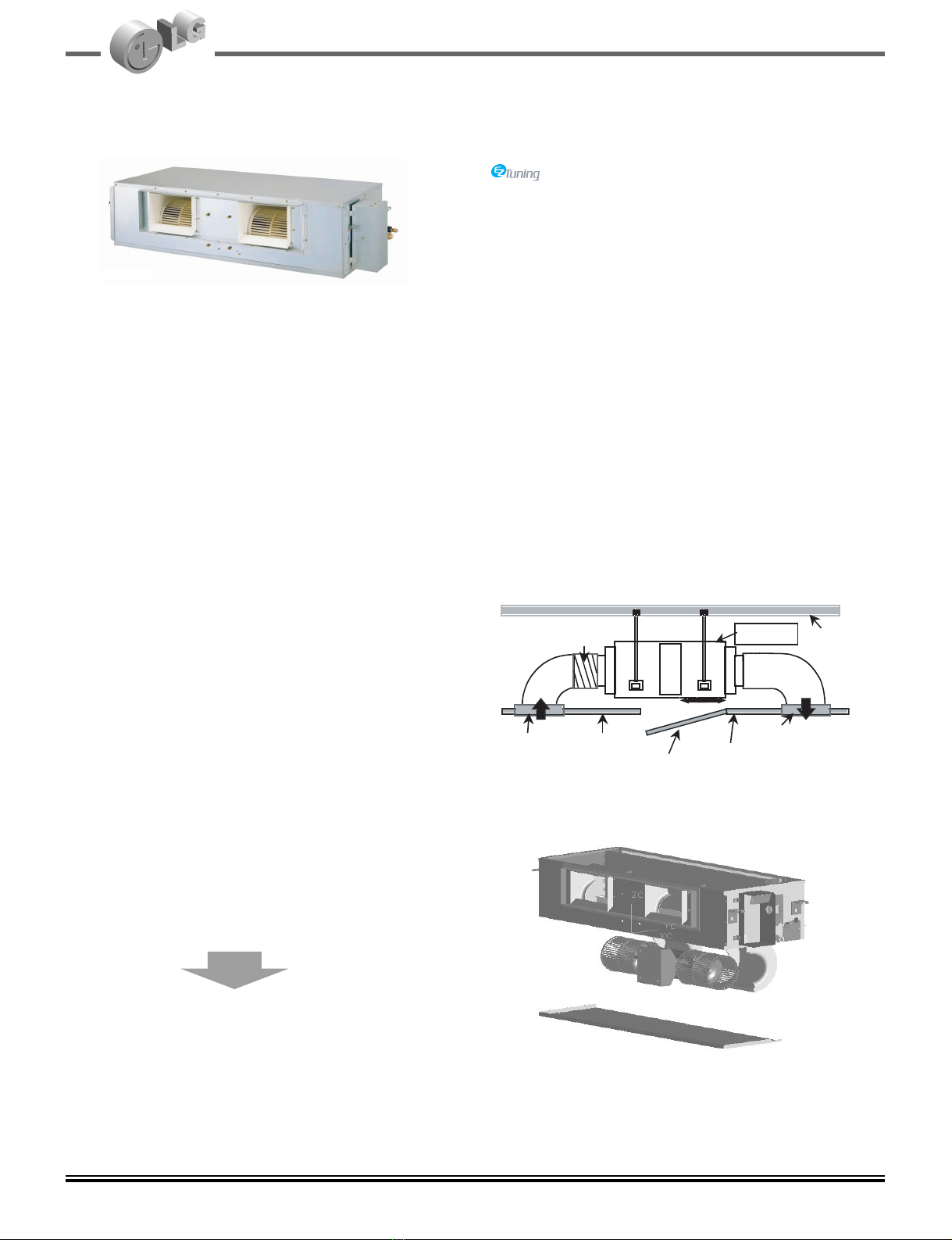
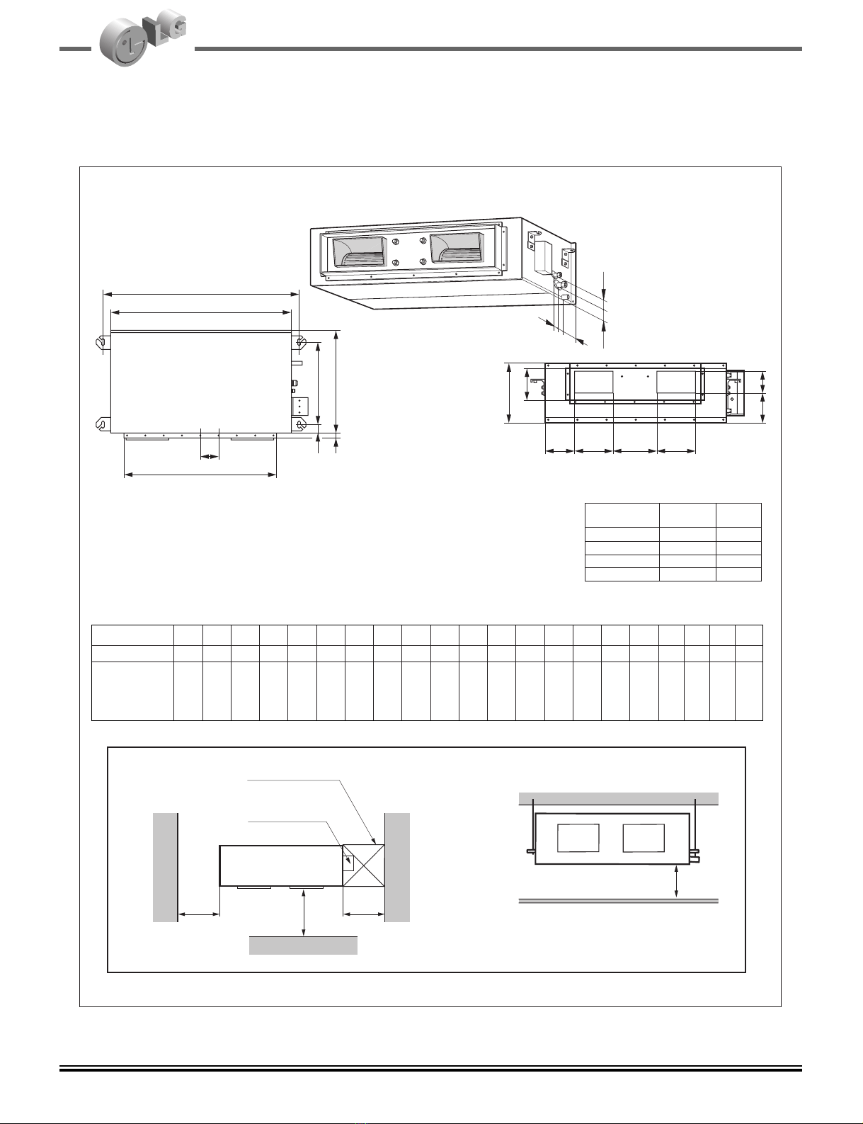
8Ceiling Concealed Duct
50Hz • R410A • Heat Pump Specifications
Notes: 1. Capacities are based on the following conditions:
Cooling: - Indoor Temperature 27°C(80.6°F) DB /19 °C(66.2°F) WB Heating: - Indoor Temperature 20°C(68°F) DB / 15°C(59°F) WB
- Outdoor Temperature 35 °C(95°F) DB /24 °C(75.2°F) WB - Outdoor Temperature 7°C(44.6°F) DB / 6°C(42.8°F) WB
- Interconnecting Piping Length 7.5m - Interconnecting Piping Length 7.5 m
- Level Difference of Zero. - Level Difference of Zero.
2. Capacities are Net Capacities.
3. Due to our policy of innovation some specifications may be changed without notification.
Item Unit
Cooling Capacity kcal/h(W)
Btu/h
Heating Capacity kcal/h(W)
Btu/h
Input Cooling W
Heating W
Running Current Cooling A
Heating A
Starting Current Cooling A
Heating A
Power Supply Ø,V,Hz
Power Factor %
Electric Heater ( Optional ) KW
E.E.R Cooling kcal/hrW(W/W)
Btu/hW
C.O.P Heating kcal/hrW(W/W)
Btu/hW
Setting Temperature Range Cool °C
Heat °C
Dehumidification Rate l/h
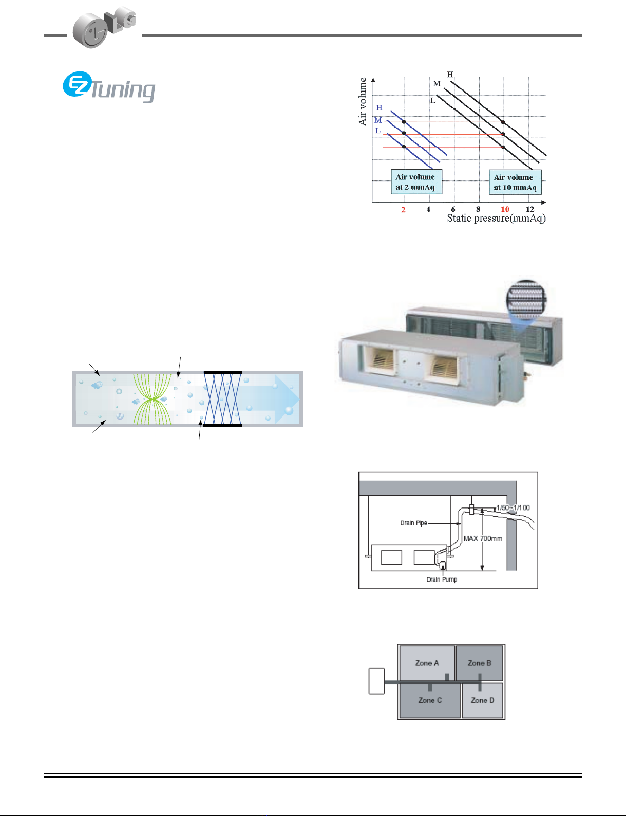
External Static Pressure mm Aq
Refrigerant Control Type
Refrigerant charge g(oz),type
Indoor Fan motor Output W
Type
Model
No.ofPoles
Input W
Running Current A
Capacitor µF/Vac
Indoor Fan Type
No. Used / Diameter EA/ (mm)
Motor Step
Indoor Fan RPM Cooling(H/M/L)
Heating(H/M/L)
Air Circulation Indoor(H/M/L) CMM(CFM)
Noise Level (SoundPress,1m) Indoor(H/M/L) dB(A)±3
Temperature Controller
Indoor Coil Tube Size (OD) inch(mm)
Fins per inch
No of Rows & Column
Dimensions (W*H*D) Indoor inch(mm)
Net Weight indoor kg(lbs)
Compressor Locked Rotor Amp. A
Type
Quantity
Model
maker
Capacity kcal/hr(Btu/h)
Motor Type
Motor Input W
Oil Type
Oil Charge CC
PTCR _
O.L.P Type(model name)
Outdoor Coil Tube Size (OD) inch(mm)
Fins per inch
No of Rows & Column
Outdoor Fan motor Output W
Model
Input W
Running Current A
No.ofPoles
Capacitor µF/Vac
Outdoor Fan Type
No. Used / Diameter EA/ inch(mm)
Discharge Side / Top
Speed rpm
Air Circulation Outdoor CMM(CFM)
Noise Level (SoundPress,1m) Outdoor dB(A)±3
SVC Valve Liquid inch(mm)
Gas
Dimensions (W*H*D) Outdoor inch(mm)
Net Weight Outdoor kg(lbs)
Power Supply Cable No.* mm2
Connecting Cable No.* mm2
Connecting Tube Liquid Side inch(mm)
(Ø. Socket Flare) Gas Side inch(mm)
Length, std m
Max length/Elevation m
Drain Hose In diameter mm
Out diameter mm
Packing Dimension (W*H*D) Indoor inch(mm)
Outdoor inch(mm)
Stuffing Quantity With S/Parts 20/40ft
Without S/Parts 20/40ft
AB-H246HTA0[B24AHV SH0] AB-H306GTA0[B30AHV SG0] AB-H366GTA0[B36AHV SG0]
5,795(6,740) 8063(9378) 8568(9964)
23,000 32,000 34000
6,551(7,619) 9449(10990) 9828(11430)
26,000 37,500 39000
2,500 3,300 3450
2,700 3,400 3550
11.0 15.1 15.5
12.0 16.0 16
48.0 125.0 125
46.0 125.0 125
1,220-240,50 1,220-240,50 1,220-240,50
---
---
2.32(2.70) 2.44(2.84) 2.48(2.89)
9.21 9.69 9.9
2.42(2.82) 2.78(3.23) 2.77(3.22)
9.62 11.02 10.99
18~30 18~30 18~30
16~30 16~30 16~30
2.64 3.2 3.3
688
Capillary Tube Capillary Tube Capillary Tube
2930(103.4) , R410a 2600(91.7),R410A 2600(91.7),R410A
118 272 272
condenser inducted condenser inducted condenser inducted
IC-13450LG13C IC-13450LG13A IC-13450LG13A
444
180 323 323
0.92 1.42 1.42
6/370 6/370 6/370
Sirocco Fan Sirocco Fan Sirocco Fan
2/Ø177 2/Ø177 2/Ø177
333
1127/1037/937 1384(High) 1384(High)
1127/1037/937 1384(High) 1384(High)
18/16.5/14(636/583/494) 32/29/26.5(1130/1024/936) 32/29/26.5(1130/1024/936)
37/35/33 42/40/38 42/40/38
Thermistor Thermistor Thermistor
0.275(7.0) 0.275(7.0) 0.275(7.0)
21 21 21
3R 10C 3R 12C 3R 12C
34.6/10.2/17.7(880*260*450) 46.4*11.7 *17.71(1180*298*450) 46.4*11.7 *17.71(1180*298*450)
34(74.9) 38(83.8) 38(83.8)
62 88/96 88/96
Rotary Rotary Rotary
111
GP290PAC NN40VAAMT NN40VAAMT
LG SIAM SIAM
6,225(24,700)/6,275(24,900) 8770(34802)/8860(35158) 8770(34802)/8860(35158)
PSC PSC PSC
2,470/2,541 3430/3530 3430/3530
FVC68D MEL 56 MEL 56
1130±10 1300 1300
---
Internal Internal Internal
0.275(7.0) 0.275(7) 0.275(7)
18 18 18
1R(2R) 30C 2R34C 2R34C
90 189 189
IC-14654 LG97C IC-13670LG39D IC-13670LG39D
168 280 280
0.74 1.28 1.28
666
6.0/370 6/370 6/370
Propeller Propeller Propeller
1/16.5(420) 1/20.7(526) 1/20.7(526)
Top Discharge Top Discharge Top Discharge
900 930 930
55(1,940) 92(3245) 92(3245)
60 68 68
1/4(6.35) 1/4(6.35) 1/4(6.35)
1/2(12.7) 5/8(15.88) 5/8(15.88)
24.6/27.7/22.7(626*703*576) 28*32.6*27(712*828*687) 28*32.6*27(712*828*687)
60(132.3) 75(165.3) 75(165.3)
3*5.5 3*5.5 3*5.5
5*1.25 5*1.25 5*1.25
1/4(6.35) 1/4(6.35) 1/4(6.35)
1/2(12.7) 5/8(15.88) 5/8(15.88)
7.5 7.5 7.5
50/30 50/30 50/30
22.6 22.6 22.6
25.4 25.4 25.4
44.7*13.4*22.2(1135*340*565) 56.5*14.8*23.0(1435*375*585) 56.5*14.8*23.0(1435*375*585)
27.9*29.3*26.0(710*745*660) 31.1*35.0*30.1(790*890*765) 31.1*35.0*30.1(790*890*765)
45/96 30/66 30/66
41/86 27/58 27/58
GeneralIndoorOutdoor
Other


 null")