LG AMNH096BTG0 User manual

Multi Type Air Conditioner
SVC MANUAL(Exploded View)
MODEL
Internal Use Only
http://biz.lgservice.com
CAUTION
Before Servicing the unit, read the safety precautions in General SVC manual.
Only for authorized service personnel.
Duct Type
AMNH096BTG0
AMNH126BTG0
AMNH186BTG0
AMNH096BPA0
AMNH126BPA0
AMNH186BHA0
AMNH246BHA0
AMNC246BHA0
AMNH306BGA0
AMNC306BGA0
AMNH366BGA0
AMNC366BGA0
AMNH09GB1A0
AMNH12GB1A0
AMNH18GB2A0
AMNH24GB2A0
AMNH076LQL0
AMNH096LQL0
AMNH096LRL0
AMNH126LRL0
AMNH186LTL0
AMNH246LTL0
AMNH07GD4L0
AMNH09GD4L0
AMNH12GD4L0
AMNH18GD5L0
AMNH24GD5L0
AMNH096AP*1
AMNH126AP*1
4 Way CST
AMNH096TEC0
AMNH126TEC0
AMNH186TEC0
AMNH246TFC0
AMNH306TFC0
AMNH366TDC0
AMNH306TFA0
AMNC306TFC0
AMNC366TDC0
AMNH09GTEF0
AMNH12GTEF0
AMNH18GTEF0
AMNH24GTHF0
CVT
AMNH096VEA0
AMNH126VEA0
AMNH186VBA0
AMNH246VBA0
Art Cool Type
• Indoor Unit:
• Outdoor Unit: A2UW146FA0 A2UW146FA1 A2UW146FA2
A2UW166FA0 A2UW166FA1 A2UW186FA0
A3UW186FA0 A3UW186FA1 A3UW246FA0
A4UW246FA0 A4UW24GFA0 A4UW30GFA0
A4UW306FA0 A4UW306FA1 A6UW406FA0
Room Type 1 Way CST
AMNH096TCC0
AMNC096TCC0
AMNH126TCC0
AMNC126TCC0
AMNH09GTCC0
AMNH12GTCC0
AMNH076DZ*0
AMNH096DU*0
AMNH126DU*0
AMNH186D3*0
AMNH246D3*0
AMNH07GDZ*0
AMNH09GDU*0
AMNH12GDU*0
AMNH18GD3*0
AMNH24GD3*0
AMNH07GDE*0
AMNH09GDE*0
AMNH12GDE*0
Art Cool Deluxe Type

- 2 -
Copyright ©2007 LG Electronics. Inc. All right reserved.
Only for training and service purposes LGE Internal Use Only
Multi type Air Conditioner Service Manual
TABLE OF CONTENTS
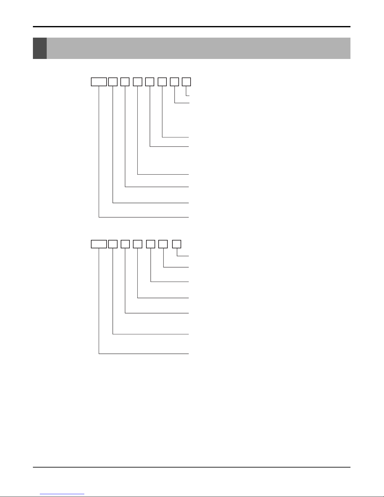
Model Number Nomenclature ....................................................................................................................3
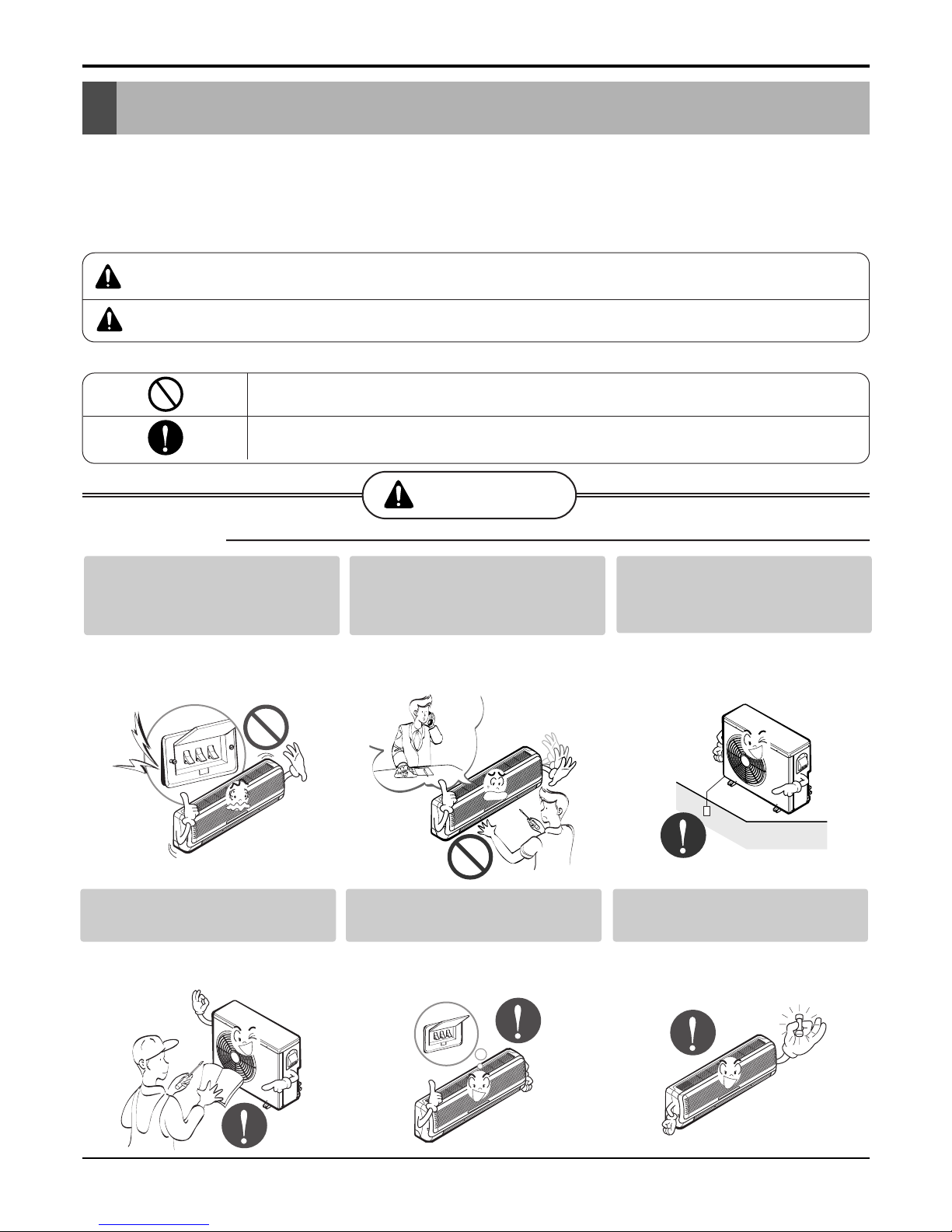
Symbols Used in this Manual ...................................................................................................................5
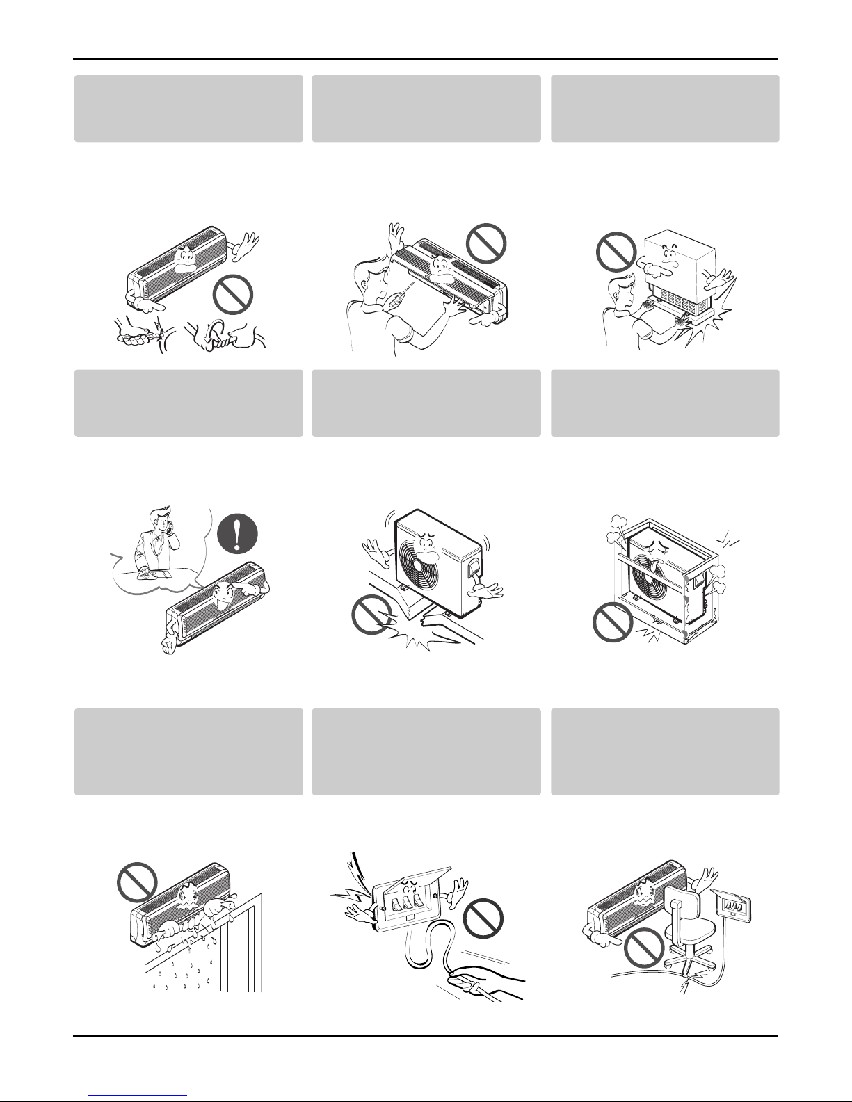
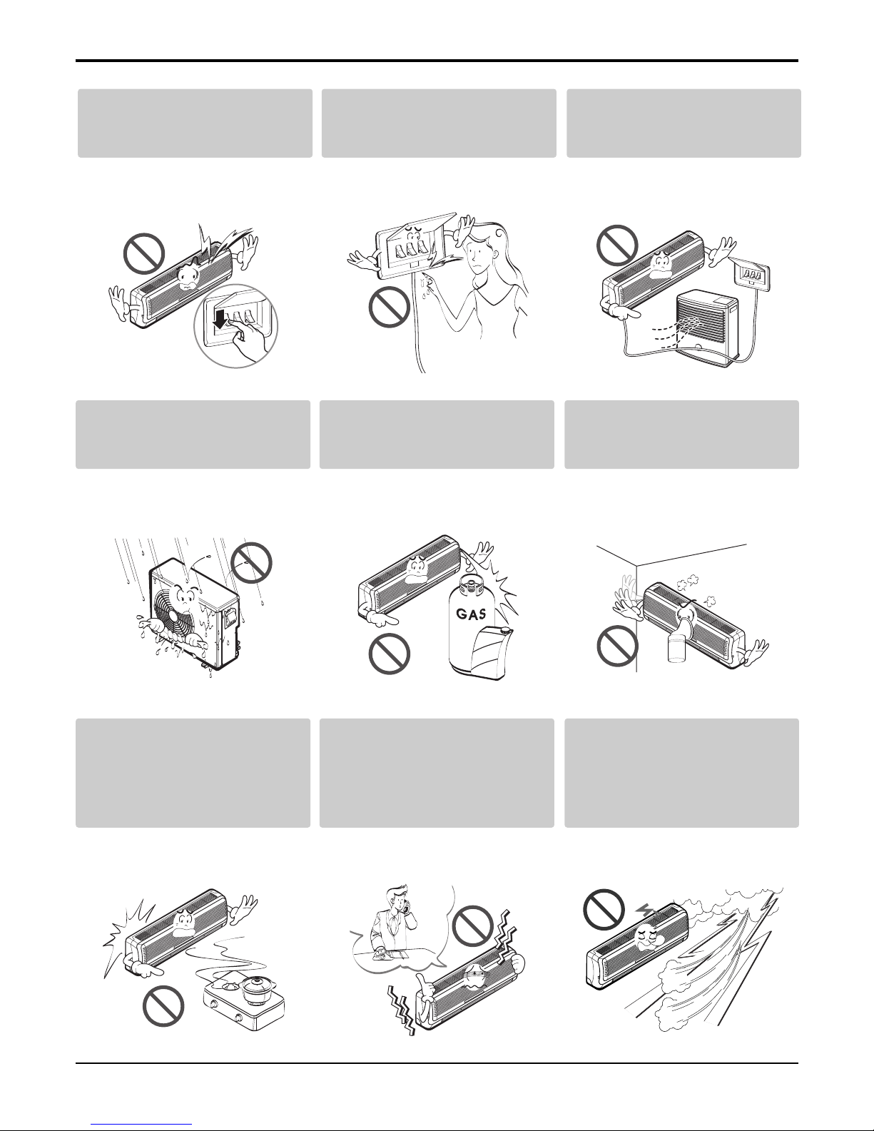
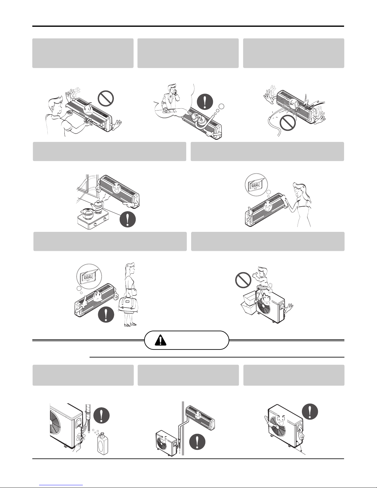
Safety Precautions......................................................................................................................................6
Dimensions................................................................................................................................................12
Indoor Unit..............................................................................................................................................12
Outdoor Unit ...........................................................................................................................................21
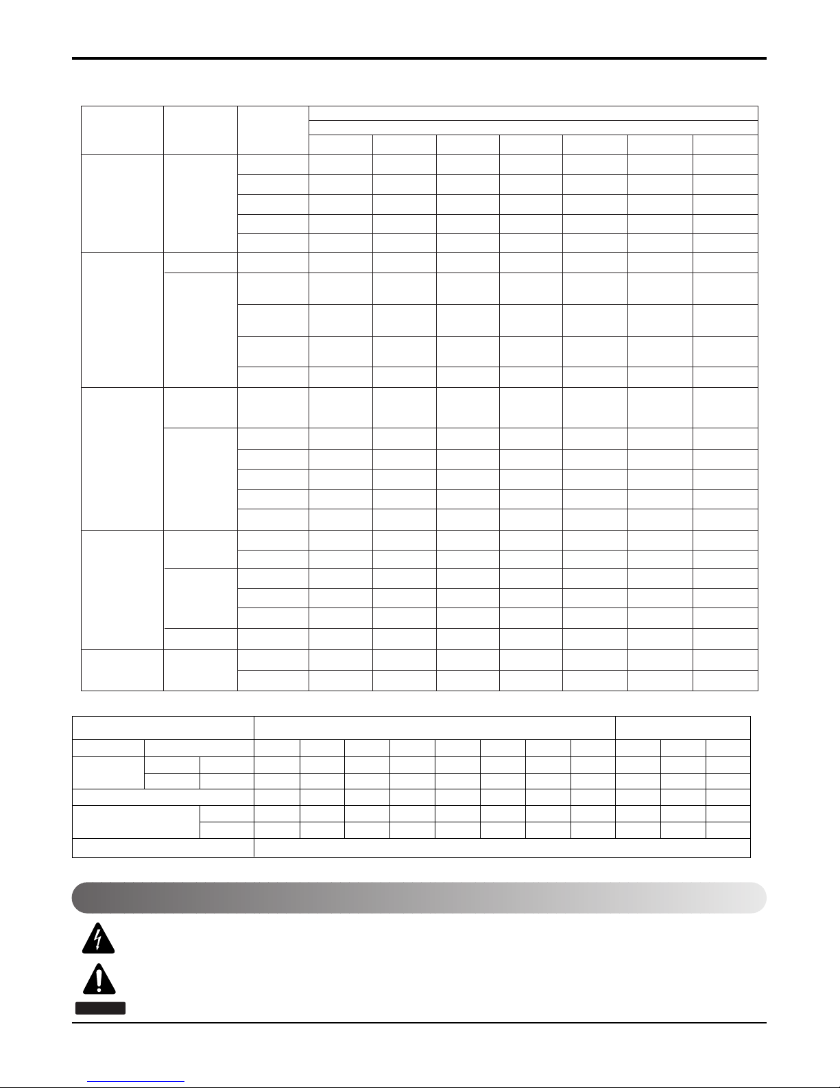
Product Specifications ............................................................................................................................22
Installation .................................................................................................................................................34
Select the best location of indoor unit ....................................................................................................34
How to fix ...............................................................................................................................................37
Piping and Drainage of Indoor Unit ........................................................................................................45
Connection of indoor unit piping.............................................................................................................46
Remote Controller Installation ................................................................................................................69
Connecting Pipings and the cable to Outdoor unit .................................................................................71
Checking the Drainage and Pipe forming...............................................................................................74
Maximum Length of Pipe and Extra Charge of Refrigerant Charge.......................................................79
Test Running ..........................................................................................................................................85
System Layout and Piping Length..........................................................................................................88
Installation ..............................................................................................................................................89
Installation of The Main Unit...................................................................................................................90
Connection of Piping ..............................................................................................................................91
Connection of Wiring ..............................................................................................................................92
Operation ..................................................................................................................................................93
Function of control..................................................................................................................................93
Function of Indoor Unit ...........................................................................................................................98
Function of Outdoor Unit ......................................................................................................................104
Remote Control Operation ...................................................................................................................105
Control Devices and Function ...............................................................................................................114
Simple Central Control .........................................................................................................................114
Term of Each part and Function ...........................................................................................................114
Electrical wiring ....................................................................................................................................115
Deluxe Central Control .........................................................................................................................121
Disassembly of the parts (Indoor unit) .................................................................................................127
Indoor unit ............................................................................................................................................127
Schematic Diagram.................................................................................................................................142
Electronic Control Device .....................................................................................................................142
Wiring Diagram.....................................................................................................................................154
Components Locations.........................................................................................................................160
Troubleshooting Guide...........................................................................................................................179
Refrigeration Cycle Diagram ................................................................................................................179
Self-diagnosis Function ........................................................................................................................186
Cycle Troubleshooting Guide................................................................................................................187
Electronic Parts Troubleshooting Guide ...............................................................................................188
General Information..............................................................................................................................193
(3-way) Valve ...........................................................................................................................................209
Exploded View.........................................................................................................................................213
Indoor Unit ...........................................................................................................................................213
Outdoor Unit ........................................................................................................................................242

- 3 -
Copyright ©2007 LG Electronics. Inc. All right reserved.
Only for training and service purposes LGE Internal Use Only
Model Number Nomenclature
Indoor Unit
Outdoor Unit
AMN H 6
07 QLA0
Serial Number
A2U W 618 F A 0
Electrical Ratings
TPS Inverter Multi System Indoor Unit
Model Type
H : Heat Pump
Ex) 7,000 Btu/h '07', 18,000 Btu/h '18'
Nominal Cooling Capacity in Btu/h
Electrical Rating
6 : 1Ø, 220-240V, 50Hz G : 220~240V, 50/60Hz
Chassis Name
Indoor Unit Type
L : Wall Mounted , A : ART COOL
D : ART COOL DELUXE, T : Ceiling Cassette
B : Ceiling Concealed Duct
V : Ceiling & Floor(Convertible) D : D Look (Wall Mounted)
Function
A : Basic, L : Nano Plasma + Auto Clean(Wall Mounted)
C: Plasma(Ceiling Cassette), G: Low Static Motor
ART COOL(DELUXE) Type Front Panel Color
B : Blue, D : Wood, M : Meta, R : Mirror, W : White
R410A
TPS Inverter Multi
System Outdoor Unit.
And No. of Connectable Indoor Units
Ex) A2U : Connectable max. 2 Indoor Units
A6U : Connectable max. 6 Indoor Units
Model Type
W : DC Inverter Heat Pump
Ex) 18,000 Btu/h '18', 48,000 Btu/h, 50Hz '48'
Nominal Cooling Capacity in Btu/h
6 : 1Ø, 220-240V, 50Hz
8 : 3Ø, 380-415V, 50Hz
Multi Type
Function
A : Basic
F : Free Joint Multi Type
Serial Number

- 4 -
Copyright ©2007 LG Electronics. Inc. All right reserved.
Only for training and service purposes LGE Internal Use Only
Model Number Nomenclature
Panel (Cassette, Built in Duct)
PT-CFA 3721A10072B 8435002992862 COOLING
TF PT-CFC 3721A10072G 8435002992879 COOLING + PLASMA
PT-HFA 3821A10072A 8435002992886 HEATING
PT-HFC 3721A10072E 8435002992893 HEATING + PLASMA
PT-CCA 3721A10023Z 8435002994095 COOLING
TC,TC1 PT-CCC 3721A10023W 8435002994101 COOLING + PLASMA
PT-HCA 3721A10023Y 8435002994118 HEATING
CST PANEL PT-HCC 3721A10023V 8435002994125 HEATING + PLASMA
PT-HEA 3721A10105A 8435002992978 HEATING
TE(family look) PT-HEC 3721A10105B 8435002992985 HEATING + PLASMA
PT-CEA 3721A10105C 8435002992954 COOLING
PT-CEC 3721A10105D 8435002992961 COOLING + PLASMA
TE1(family look) PT-HEA1 3721A10105M HEATING
PT-HEC1 3721A10105N HEATING + PLASMA
PT-HAD 3721A10106A 8435002994057 HEATING
TD(family look) PT-HDC 3721A10106B 8435002994064 HEATING + PLASMA
PT-CDA 3721A10106C 8435002994071 COOLING
PT-CDC 3721A10106D 8435002994088 COOLING + PLASMA
TH(family look) PT-HDA1 3721A10106X HEATING
PT-HDC1 3721A10106Z HEATING + PLASMA
BUILT IN DUCT BP PB-HPA 3721A20168A 9K/12K
BQ PB-HQA 3721A20168B 18K/24K
Category CHASSIS PANEL NAME PANEL P/NO. SERIAL NO. Remark
123456
PT -HEA
Basic A
B
Plasma Filter C
D
Elevation Grille E
Elevation Grille + Plasma Filter F
TE/TB/TD Before 2003 : Basic 0
TE/TD Before 2003 : Plasma Filter 1
6. Function
5. Chassis Name
Function
Number Contents
1, 2 Panel for Cassette
3-
4 Cooling/Heatpump
5 Chassis Name
6 Function
Chassis Abbrevation
TC C
TB B
TD D
TE E
TF F
TH H
TJ J
BP P
BQ Q

- 5 -
Copyright ©2007 LG Electronics. Inc. All right reserved.
Only for training and service purposes LGE Internal Use Only
Model Number Nomenclature
Indoor Units
Outdoor Units
2.1
(7000) 2.6
(9000) 3.5
(12000) 5.3
(18000) 7.0
(24000) 8.8
(30000) 10.6
(36000)
SQ AMNH
076LQL0 AMNH
096LQL0 -- - - -
SR -AMNH
096LRL0 AMNH
126LRL0 ----
ST
S4
S5
---
AMNH
186LTL0 AMNH
246LTC0 --
General SP1 -AMNN
096AP*1 AMNN
126AP*1 ----
SZ AMNH
076DZ*0
07GDZ*0
AMNH
07GDE*0 AMNH
09GDE*0 AMNH
12GDE*0
--- - - -
SU
S3
SE
---
----
1Way TC,TC1
-AMNH/C
096TCC0 AMNH/C
126TCC0
AMNH09
GTCC0 AMNH12
GTCC0
----
----
--
TE
TE1
-
-
AMNH
096TEC0 AMNH
126TEC0 AMNH
186TEC0
AMNH
09GTEF0 AMNH
12GTEF0 AMNH
18GTEF0
-- -
-- -
--
TF
TH
----
----
AMNH
246TFC0
AMNH
24GTHF0
AMNH/C
306TF*0 -
TD ---- --
AMNH/C
366TDC0
BH ---
AMNH
186BHA0 AMNH
246BHA0 --
BG ---- -
AMNH/C
306BGA0 AMNH
366BGA0
Low
Static
BT
B1
B2
-
-----
-- - - -
AMNH
096BTG0 AMNH
126BTG0 AMNH
186BTG0
AMNH
09GB1A0 AMNH
12GB1A0
AMNH
18GB2A0 AMNH
24GB2A0
-- -
Built in BP -AMNH
096BPA0 AMNH
126BPA0 ----
VE -AMNH
096VEA0 AMNH
126VEA0 ----
VB ---
AMNH
186VBA0 AMNH
246VBA0 --
Chasiss
Model Name
Capacity, kW(Btu/h)
Wall
Mounted General
Ceiling &
Floor Convertible
Category Type
ART
Cool Mirror
Ceiling
Cassette 4Way
Ceiling
Concealed
Duct
High
Static
AMNH
07GD4L0 AMNH
09GD4L0 AMNH
12GD4L0
AMNH
18GD5L0 AMNH
24GD5L0
AMNH
096DU*0
09GDU*0
AMNH
126DU*0
12GDU*0
AMNH
186D3*0
18GD3*0
AMNH
246D3*0
24GD3*0
Notes :
A2UW146FA0/1/2, A2UW166FA0/1, A2UW186FA0 and A3UW186FA0/1 are not TPS inverter system but one inverter compressor system.
TPS Inverter Multi Series Multi Piping Type Distributor Type
Heat Pump Model Name
Rated Capacity Cooling kW(Btu/h)
Heating kW(Btu/h)
Number of Indoor Units to be Connected
Indoor Units kW
Connectable Capacity Btu/h
Power Supply
A2UW146FA0/1/2
A2UW166FA0/1 A2UW186FA0 A3UW186FA0/1 A3UW246FA0 A4UW246FA0 A4UW306FA0 A4UW306FA1 A6UW406FA0 A7UW486FA0 A8UW566FA0
4.1(14000) 4.7(16000) 5.3(18000) 5.3(18000) 7.0(24000) 7.0(24000) 8.8(30000) 8.8(30000) 11.7(40000) 14.0(48000) 16.4(56000)
4.7(16000) 5.3(18000) 6.3(21600) 6.3(21600) 8.2(28000) 8.2(28000) 10.1(34500) 10.1(34500) 13.5(46000) 16.2(55200) 18.9(64400)
Max.2 Units Max.2 Units Max.2 Units Max.3 Units Max.3 Units Max.4 Units Max.4 Units Max.4 Units Max.6 Units Max.7 Units Max.8 Units
2.1~6.2 2.1~7.0 2.1~7.0 2.1~8.8 2.1~9.7 2.1~11.4 2.1~11.4 2.1~11.4 4.7~15.2 5.6~18.3 6.6~21.3
7000~21000 7000~24000 7000~24000 7000~30000 7000~33000 7000~39000 7000~39000 7000~39000 16000~52000 19200~62400 22400~72800
1Ø, 220-240V, 50Hz
This symbol alerts you to the risk of electric shock.
This symbol alerts you to hazards that could cause harm to the
air conditioner.
This symbol indicates special notes.
NOTICE
Symbols Used in this Manual

- 6 -
Copyright ©2007 LG Electronics. Inc. All right reserved.
Only for training and service purposes LGE Internal Use Only
Safety Precautions
Safety Precautions
To prevent injury to the user or other people and property damage, the following instructions must
be followed.
■Incorrect operation due to ignoring instruction will cause harm or damage. The seriousness is
classified by the following indications.
■Meanings of symbols used in this manual are as shown below.
WARNING
CAUTION
This symbol indicates the possibility of death or serious injury.
This symbol indicates the possibility of injury or damage to properties only.
WARNING
■Installation
Be sure not to do.
Be sure to follow the instruction.
Do not use a defective or under-
rated circuit breaker. Use this
appliance on a dedicated circuit.
• There is risk of fire or electric
shock.
For electrical work, contact the
dealer, seller, a qualified electrician,
or an Authorized Service Center
.
• Do not disassemble or repair the
product. There is risk of fire or
electric shock.
Always ground the product.
• There is risk of fire or electric
shock.
Install the panel and the cover
of control box securely.
• There is risk of fire or electric
shock.
Always install a dedicated cir-
cuit and breaker.
• Improper wiring or installation may
cause fire or electric shock
Use the correctly rated break-
er or fuse.
• There is risk of fire or electric
shock.

- 7 -
Copyright ©2007 LG Electronics. Inc. All right reserved.
Only for training and service purposes LGE Internal Use Only
Safety Precautions
Do not modify or extend the
power cable.
• There is risk of fire or electric
shock.
Do not install, remove, or re-
install the unit by yourself
(customer).
• There is risk of fire, electric shock,
explosion, or injury.
Be cautious when unpacking
and installing the product.
• Sharp edges could cause injury.
Be especially careful of the case
edges and the fins on the con-
denser and evaporator.
For installation, always con-
tact the dealer or an
Authorized Service Center.
• There is risk of fire, electric shock,
explosion, or injury.
Do not install the product on a
defective installation stand.
• It may cause injury, accident, or
damage to the product.
Be sure the installation area
does not deteriorate with age.
• If the base collapses, the air condi-
tioner could fall with it, causing
property damage, product failure,
and personal injury.
Do not let the air conditioner
run for a long time when the
humidity is very high and a
door or a window is left open.
• Moisture may condense and wet or
damage furniture.
Take care to ensure that
power cable could not be
pulled out or damaged during
operation.
• There is risk of fire or electric
shock.
Do not place anything on the
power cable.
• There is risk of fire or electric
shock.

- 8 -
Copyright ©2007 LG Electronics. Inc. All right reserved.
Only for training and service purposes LGE Internal Use Only
Safety Precautions
Do not allow water to run into
electric parts.
• It may cause There is risk of fire,
failure of the product, or electric
shock.
Do not store or use flammable
gas or combustibles near the
product.
• There is risk of fire or failure of
product.
Do not use the product in a
tightly closed space for a long
time.
• Oxygen deficiency could occur.
When flammable gas leaks,
turn off the gas and open a
window for ventilation before
turn the product on.
• Do not use the telephone or turn
switches on or off. There is risk of
explosion or fire
If strange sounds, or small or
smoke comes from product.
Turn the breaker off or discon-
nect the power supply cable.
• There is risk of electric shock or
fire.
Stop operation and close the
window in storm or hurricane.
If possible, remove the prod-
uct from the window before
the hurricane arrives.
• There is risk of property damage,
failure of product, or electric shock.
Do not plug or unplug the
power supply plug during
operation.
• There is risk of fire or electric
shock.
Do not touch(operate) the
product with wet hands.
• There is risk of fire or electrical
shock.
Do not place a heater or other
appliances near the power
cable.
• There is risk of fire and electric
shock.
Gasolin

- 9 -
Copyright ©2007 LG Electronics. Inc. All right reserved.
Only for training and service purposes LGE Internal Use Only
Safety Precautions
Do not open the inlet grill of the product
during operation. (Do not touch the elec-
trostatic filter, if the unit is so equipped.)
• There is risk of physical injury,
electric shock, or product failure.
When the product is soaked
(flooded or submerged), contact
an Authorized Service Center.
• There is risk of fire or electric
shock.
Be cautious that water could
not enter the product.
• There is risk of fire, electric shock,
or product damage.
Ventilate the product from time to time when
operating it together with a stove, etc.
• There is risk of fire or electric shock.
Turn the main power off when cleaning or
maintaining the product.
• There is risk of electric shock.
When the product is not be used for a long time, dis-
connect the power supply plug or turn off the breaker.
• There is risk of product damage or failure, or unintend-
ed operation.
Take care to ensure that nobody could step on
or fall onto the outdoor unit.
• This could result in personal injury and product dam-
age.
Always check for gas (refrigerant) leak-
age after installation or repair of product.
• Low refrigerant levels may cause
failure of product.
Install the drain hose to ensure that
water is drained away properly.
• A bad connection may cause water
leakage.
Keep level even when
installing the product.
• To avoid vibration or water leak-
age.
CAUTION
■Installation
90°

- 10 -
Copyright ©2007 LG Electronics. Inc. All right reserved.
Only for training and service purposes LGE Internal Use Only
Do not block the inlet or outlet
of air flow.
• It may cause product failure.
Use a soft cloth to clean. Do
not use harsh detergents, sol-
vents, etc.
• There is risk of fire, electric shock,
or damage to the plastic parts of
the product.
Do not touch the metal parts of
the product when removing the
air filter. They are very sharp!
• There is risk of personal injury.
Safety Precautions
Do not install the product
where the noise or hot air
from the outdoor unit could
damage the neighborhoods.
• It may cause a problem for your
neighbors.
Use two or more people to lift
and transport the product.
• Avoid personal injury.
Do not install the product
where it will be exposed to
sea wind (salt spray) directly.
• It may cause corrosion on the
product. Corrosion, particularly on
the condenser and evaporator fins,
could cause product malfunction or
inefficient operation.
Do not expose the skin directly to cool air for
long periods of time.
(Don't sit in the draft.)
• This could harm to your health.
Do not use the product for special purposes,
such as preserving foods, works of art, etc. It
is a consumer air conditioner, not a precision
refrigeration system.
• There is risk of damage or loss of property.
■Operational
Wax
Thinner

- 11 -
Copyright ©2007 LG Electronics. Inc. All right reserved.
Only for training and service purposes LGE Internal Use Only
Do not step on or put anyting
on the product. (outdoor
units)
• There is risk of personal injury and
failure of product.
Always insert the filter secure-
ly. Clean the filter every two
weeks or more often if neces-
sary.
• A dirty filter reduces the efficiency
of the air conditioner and could
cause product malfunction or dam-
age.
Do not insert hands or other
objects through the air inlet or
outlet while the product is
operated.
• There are sharp and moving parts
that could cause personal injury.
Do not drink the water drained
from the product.
• It is not sanitary and could cause
serious health issues.
Use a firm stool or ladder
when cleaning or maintaining
the product.
• Be careful and avoid personal
injury.
Replace the all batteries in the
remote control with new ones
of the same type. Do not mix
old and new batteries or dif-
ferent types of batteries.
• There is risk of fire or explosion
Do not recharge or disassemble the batteries.
Do not dispose of batteries in a fire.
• They may burn or explode.
If the liquid from the batteries gets onto your
skin or clothes, wash it well with clean water.
Do not use the remote if the batteries have
leaked.
• The chemicals in batteries could cause burns or other
health hazards.
Safety Precautions

- 12 -
Copyright ©2007 LG Electronics. Inc. All right reserved.
Only for training and service purposes LGE Internal Use Only
Dimensions
Dimensions
Indoor Unit
1. Split Type Indoor 2. Art Cool Type Indoor Unit
Pipe Hole
Fix Hole
Hanger Hole
H
WD
Installation plate
D
H
W
W mm 824 900 1080 840 1090 570
H mm 260 285 314 270 300 568
D mm 155 156 172 153 178 137
Model
Dimension
SQ
7k, 9k
SR
9k, 12k
ST
18k, 24k
S4
7k, 9k, 12k
S5
18k, 24k
SP
9k, 12k

- 13 -
Copyright ©2007 LG Electronics. Inc. All right reserved.
Only for training and service purposes LGE Internal Use Only
Dimensions
Installation plate
D
H
W
Installation plate
D
H
W
MODEL
DIM Unit
W mm 900 1030 1170 895
H mm 272 290 315 282
D mm 135 153 173 165
SZ
7K
SU
9K, 12K
S3
18K, 24K
SE
7K, 9K, 12K
3. Art Cool Deluxe Type
SZ,SU,S3 SE

- 14 -
Copyright ©2007 LG Electronics. Inc. All right reserved.
Only for training and service purposes LGE Internal Use Only
Dimensions
W
H
D
H
H
D
BH/BG
BP BT/BT1/B1/B2
W
WD
MODEL
DIM
W(mm) 708 1060 880 1180 580 820 1100
H(mm) 230 230 260 298 300 190 190
D(mm) 537 357 450 450 750 575 575
BT
9K/12K
BT1
18K
BH
18K/24K
BG
30K/36K
BP
9K/12K
B1
9K/12K
B2
18K/24K
4. Duct Type

- 15 -
Copyright ©2007 LG Electronics. Inc. All right reserved.
Only for training and service purposes LGE Internal Use Only
Dimensions
5. CVT Type
VE(8K/12K)
VB(18K/24K)
R
Installation plate
D
W
H
250mm
36mm
36mm 1076mm
(Rear Side)
63mm
38mm
175mm
(Installation Plate)
392mm
265mm
468mm
D
W
H
MODEL
DIM Unit
W mm 900 1200
H mm 285 615
D mm 156 205
VE
9K/12K
VB
18K/24K

- 16 -
Copyright ©2007 LG Electronics. Inc. All right reserved.
Only for training and service purposes LGE Internal Use Only
Dimensions
694.5
1050
480
846
860
328.430.8
390
893.4
931.6
16.7
50
42.7
7
155
97.7
37
116.3
141.8
180
164
194.4
91.6
180
430
130
Ø80
Ø55
180
91.6
1,000 (Ceiling opening)
931.6
893.4 (Hanging bolt)
328.4 (Hanging bolt)
860
390
30.8
430 (Ceiling opening)
4
5
6
32
1
6. CST Type - TC,TC1 (9K/12K)
(unit : mm)
Number Name Descripition
1 Liquid pipe connection ø6.35 flare
2 Gas pipe connection ø9.52 flare
3 Drain pipe connection
4 Power supply connection
5 Air discharge grill
6 Air suction grill

- 17 -
Copyright ©2007 LG Electronics. Inc. All right reserved.
Only for training and service purposes LGE Internal Use Only
CLOSE OPEN OPEN CLOSE
269
670
30
570
269
190.5
160
52
90
90
120.4 30 521
670 570
450
40
110 110
670
670
4
1
3
2
5
6
Unit:mm
570 Unit size
570 Unit size
450 (Hanging bolt)
7575
600 (Ceiling opening)
521(Hanging bolt) 39.5
39.5
7. CST Type - TE(1) (9K/12K/18K)
Dimensions
(unit : mm)
Number Name Descripition
1 Liquid pipe connection ø6.35 flare
2 Gas pipe connection
9k: Ø9.52, 12k: Ø9.52, 18k: Ø12.7 flare
3 Drain pipe connection
4 Power supply connection
5 Air discharge grill
6 Air suction grill

- 18 -
Copyright ©2007 LG Electronics. Inc. All right reserved.
Only for training and service purposes LGE Internal Use Only
8. CST Type - TF (24K/30K)
292
850
850
850
850
744
658
572
744
292
212
150
54
90
90
192 117
70
110 110
4
1
3
2
5
6
Unit:mm
744 Unit size
744 Unit size
658 (Hanging bolt)
6666
790 (Ceiling opening)
572(Hanging bolt) 109
109
30
(unit : mm)
Number Name Descripition
1 Liquid pipe connection ø6.35 flare
2 Gas pipe connection
ø12.7 flare-24K, ø15.88 flare-30K
3 Drain pipe connection
4 Power supply connection
5 Air discharge grill
6 Air suction grill
Dimensions

- 19 -
Copyright ©2007 LG Electronics. Inc. All right reserved.
Only for training and service purposes LGE Internal Use Only
9. CST Type - TH (24K)
255
950
950
950
950
840
608
688
840
225
212
150
54
90
90
192 117
70
110 110
4
1
3
2
5
6
Unit:mm
840
840
806 (Hanging bolt)
2828
862 (Ceiling opening)
688(Hanging bolt) 87
87
30
(unit : mm)
Number Name Descripition
1 Liquid pipe connection ø6.35 flare
2 Gas pipe connection
ø12.7 flare-24K, ø15.88 flare-30K
3 Drain pipe connection
4 Power supply connection
5 Air discharge grill
6 Air suction grill
Dimensions

- 20 -
Copyright ©2007 LG Electronics. Inc. All right reserved.
Only for training and service purposes LGE Internal Use Only
10. CST Type - TD(36K)
288
950
950
950
950
290
210.5
180
52
140
40
110
30
90
90
110
55
840
785
840
678
Fresh Air Inlet
Unit:mm
840 Unit size
840 Unit size
672 (Hanging bolt) 101.5101.5
875 (Ceiling opening)
785 (Hanging bolt) 45
45
4
5
6
1
3
2
Dimensions
(unit : mm)
Number Name Descripition
1 Liquid pipe connection ø6.35 flare
2 Gas pipe connection ø15.88 flare
3 Drain pipe connection
4 Power supply connection
5 Air discharge grill
6 Air suction grill
This manual suits for next models
81
Table of contents
Other LG Air Conditioner manuals
Popular Air Conditioner manuals by other brands

Mitsubishi Electric
Mitsubishi Electric MS-GK36VAT operating instructions

Mitsubishi Electric
Mitsubishi Electric MSZ-FA25VA Service manual

Samsung
Samsung AS07P2GE/XCH Owner's instructions

Fujitsu
Fujitsu AF Series operating manual

Carrier
Carrier ROOM AIR CONDITIONER operating manual

Fujitsu
Fujitsu ASY7FSACW Service manual