- 2 -
Copyright ©2009 LG Electronics. Inc. All right reserved.
Only for training and service purposes LGE Internal Use Only
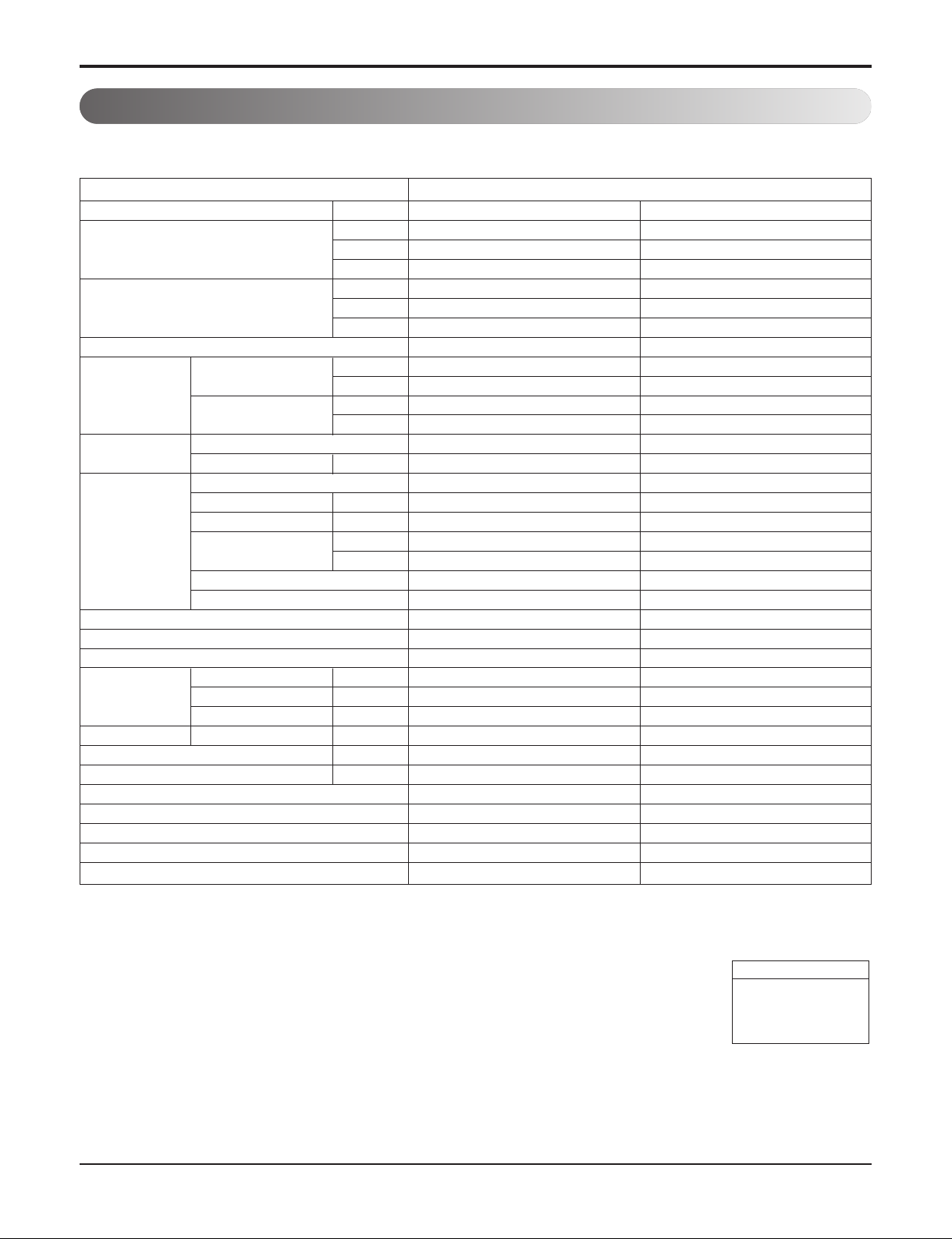
1. Specification
Type
Model Unit
kW
Cooling Capacity kcal/h
Btu/h
kW
Heating Capacity kcal/h
Btu/h
Casing
Body mm
Dimensions (WxDxH)
inch
Front Panel mm
inch
Coil
Rows x Columns x FPI
Face Area m2(ft2)
Type
Motor Output x Number
W
Running Current A
Fan Air Flow Rate(H/M/L) CMM
cfm
Drive
Motor type
Temperature Control
Sound Absorbing Thermal Insulation Material
Safety Device
Liquid Side mm(inch)
Pipe Connections
Gas Side mm(inch)
Drain Pipe(Internal Dia.)
mm(inch)
Net Weight Body kg(lbs)
Noise Level
(Sound Press, 1.5m, H/M/L)
dB(A)
Power Supply Ø, V, Hz
Refrigerant Control
Power cable
Transmission cable
Panel Color
Panel Name(Acc'y)
ARNU09GTL*4
2.8
2,400
9,600
3.2
2,800
10,900
Galvanized Steel Plate
830x550x225
32-11/16 x 21-21/32 x 8-27/32
1,050x640x28.5
41-11/32 x 25-3/16 x 1-3/32
2x11x20
0.13(1.4)
Cross Flow Fan
20x2
0.18x2
9 / 8 / 7
318 / 283 / 247
Direct
BLDC
Microprocessor, Thermostat for cooling and heating
Foamed polystrene
Fuse
Ø6.35(1/4)
Ø12.7(1/2)
25.0(1)
20.6(45.4)
36 / 34 / 32
1,220-240,50
EEV
CV 1.5 x 3C**
CVV-SB 1.0 ~ 1.5 × 2C
Morning fog
PT-HL*
ARNU12GTL*4
3.6
3,100
12,300
4.0
3,400
13,600
Galvanized Steel Plate
830x550x225
32-11/16 x 21-21/32 x 8-27/32
1,050x640x28.5
41-11/32 x 25-3/16 x 1-3/32
2x11x20
0.13(1.4)
Cross Flow Fan
20x2
0.18x2
10 / 9 / 8
353 / 318 / 283
Direct
BLDC
Microprocessor, Thermostat for cooling and heating
Foamed polystrene
Fuse
Ø6.35(1/4)
Ø12.7(1/2)
25.0(1)
20.6(45.4)
38 / 36 / 32
1,220-240,50
EEV
CV 1.5 x 3C**
CVV-SB 1.0 ~ 1.5 × 2C
Morning fog
PT-HL*
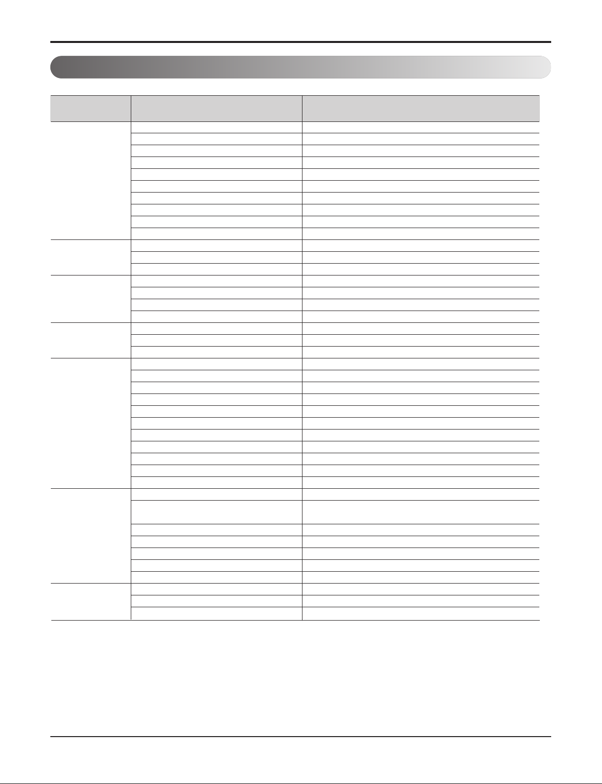
Notes:-
1. Capacities are based on the following conditions:
Cooling • Indoor temp. 27°C[80.6°F]DB/ 19°C[66.2°F]WB
• Outdoor temp. 35°C[95°F]DB/ 24°C[75.2°F]WB
• Interconnecting Piping Length 7.5m(24.6ft)
• Level Difference of Zero
Heating • Indoor temp. 20°C[68°F]DB/ 15°C[59°F]WB
• Outdoor temp. 7°C[44.6°F]DB/ 6°C[42.8°F]WB
• Interconnecting Piping Length 7.5m(24.6ft)
• Level Difference of Zero
2. Capacities are Net Capacities
3. Due to our policy of innovation some specifications may be changed without prior notification
4. To be added for more available Models
5. EEV : Electronic Expansion Valve
* Model Name
A:Basic, C:Plasma
Conversion Formula
kcal/h= kW x 860
Btu/h = kW x 3412
cfm = m3/min x 35.3
l/s = CMM x 1000/60
2Way Ceiling Cassette
** : Wiring cable size must comply with the applicable local and national codes. And “Electric characteristics” chapter should be considered for
electrical work and design. Especially the power cable and circuit breaker should be selected in accordance with that


 null")