INTRODUCTION |5
Introduction
Due to our policy of continuous product innovation, some specications may change without notication.
© LG Electronics U.S.A., Inc., Englewood Cliffs, NJ. All rights reserved. “LG” is a registered trademark of LG Corp.
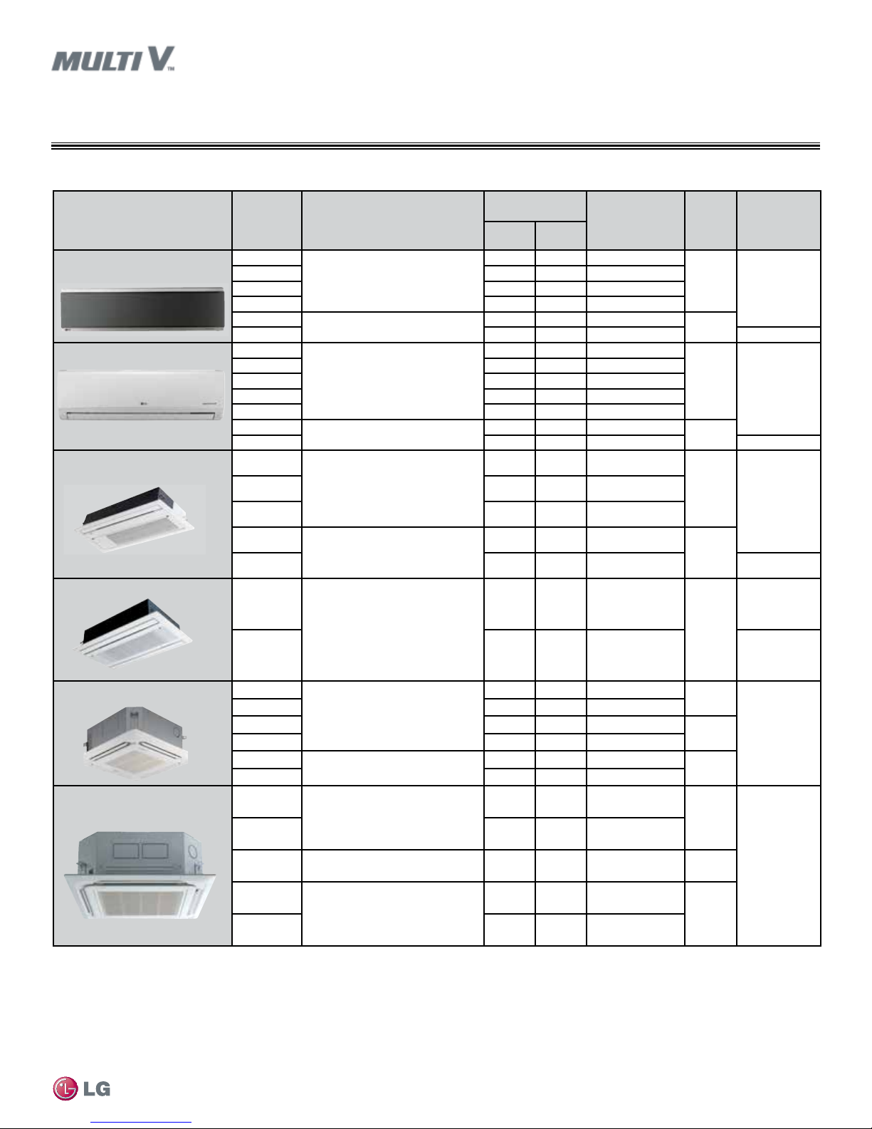
Unit/Type1ARNU*****2
Dimensions
(W x D x H)
(inches)
Nominal Capacity
Btu/h Air Flow Rate
(CFM)
(H/M/L4)
Weight
(lbs.)
Pipe
Connections
(inches, O.D.)
(Liquid, Vapor)
Cooling3Heating3
Wall Mounted–ART COOLTM
Mirror
073 SER2
36-1/16 x 6-1/2 x 11-1/8
7,500 8,500 247/212/141
25 1/4, 1/2
093 SER2 9,600 10,900 282/247/177
123 SER2 12,300 13,600 353/283/212
153 SER2 15,400 17,100 371/283/212
183 S8R2 43-9/16 x 7-7/8 x 11-13/16 19,100 21,500 508/459/388 34
243 S8R2 24,200 27,300 632/508/424 3/8, 5/8
Wall Mounted–Standard 053 SBL4
35-1/4 x 8-15/16 x 11-7/16
5,500 6,100 1,120/1,080/1,050
22 1/4, 1/2
073 SBL4 7,500 8,500 1,190/1,120/1,050
093 SBL4 9,600 10,900 1,260/1,190/1,050
123 SBL4 12,300 13,600 1,420/1,260/1,120
153 SBL4 15,400 17,100 1,550/1,350/1,190
183 SCL4 40-5/16 x 9-7/8 x 12-13/16 19,100 21,500 1,120/1,050/980 31
243 SCL4 24,200 27,300 1,280/1,140/1,000 3/8, 5/8
Ceiling Cassette–One Way 073 TUC4
Body: 33-7/8 x 17-3/4 x 6-11/16
Panel: 43-5/16 x 19-3/4 x 1-3/8
7,500 8,500 290/258/226
Body: 33
Panel: 10 1/4, 1/2
093 TUC4 9,600 10,900 325/304/290
123 TUC4 12,300 13,600 353/325/290
183 TTC4 Body: 46-1/2 x 17-3/4 x 6-7/8
Panel: 55-15/16 x 19-3/4 x 1-3/8
19,100 21,500 470/427/385 Body: 42
Panel: 13
243 TTC4 24,200 24,200 515/470/406 3/8, 5/8
Ceiling Cassette–Two Way
183 TLC4
Body: 32-11/16 x 21-5/8 x 8-7/8
Panel: 41-5/16 x 25-3/16 x 1-5/8
19,100 21,500 459/424/353
Body: 49
Panel: 11
1/4, 1/2
243 TLC4 24,200 27,300 601/530/459 3/8, 5/8
Ceiling Cassette–Four Way
(2' x 2')
053 TRC4
Body: 22-7/16 x 22-7/16 x 8-7/16
Panel: 27-9/16 x 27-9/16 x 7/8
5,500 6,100 265/247/212 Body: 29
Panel: 7
1/4, 1/2
073 TRC4 7,500 8,500 265/247/212
093 TRC4 9,600 10,900 283/265/251 Body: 32
Panel: 7
123 TRC4 12,300 13,600 307/283/247
153 TQC4 Body: 22-7/16 x 22-7/16 x 10-3/32
Panel: 27-9/16 x 27-9/16 x 7/8
15,400 17,100 388/353/328 Body: 35
Panel: 7
183 TQC4 19,100 21,500 396/388/353
Ceiling Cassette–Four Way
(3' x 3') 243 TPC4 Body: 33-1/16 x 33-1/16 x 8
Panel: 37-3/8 x 37-3/8 x 1-7/16
24,200 27,300 600/530/459 Body: 48
Panel: 13
3/8, 5/8
283 TPC4 28,000 31,500 671/565/494
363 TNC4 Body: 33-1/16 x 33-1/16 x 9-5/8
Panel: 37-3/8 x 37-3/8 x 1-7/16 36,200 40,600 883/777/706 Body: 54
Panel: 13
423 TMC4 Body: 33-1/16 x 33-1/16 x 11-5/16
Panel: 37-3/8 x 37-3/8 x 1-7/16
42,000 43,800 1,059/918/812 Body: 59
Panel: 13
483 TMC4 48,100 51,200 1,130/953/883
INDOOR UNIT OVERVIEW
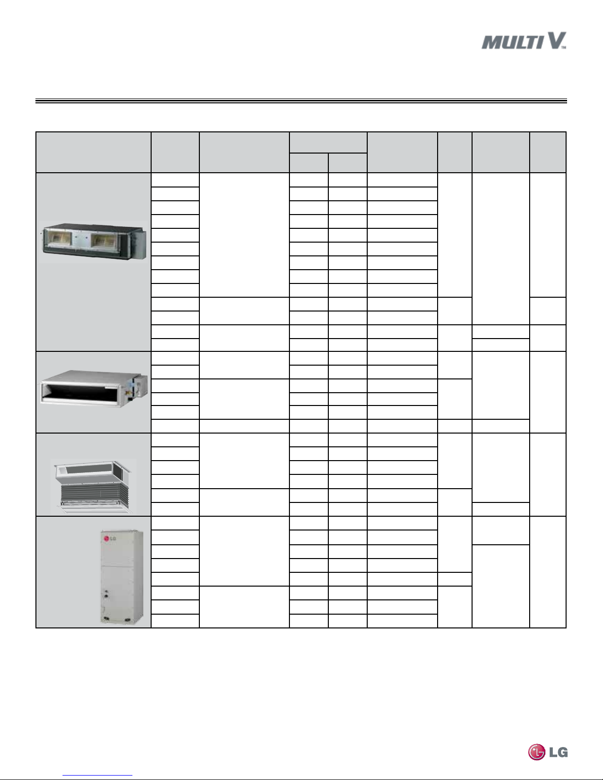
Table 1: Wall-Mounted / Ceiling Cassette Indoor Units.
1All indoor units require 208–230V/60Hz/1Ph and an AWG18-2 communication cable.
2Model number shows nominal capacity and frame size designator.
3Nominal cooling capacity rating obtained with air entering the indoor unit at 80ºF dry bulb (DB) and
67ºF wet bulb (WB) and outdoor ambient conditions of 95ºF dry bulb (DB) and 75ºF wet bulb (WB).
Nominal heating capacity rating obtained with air entering the indoor unit at 70ºF dry bulb (DB) and 60°
F wet bulb (WB) and outdoor ambient conditions of 47ºF dry bulb (DB) and 43ºF wet bulb (WB).
4H/M/L = High/Medium/Low
Wall-Mounted / Ceiling Cassette


 null")