LG C6000 User manual

LG
Room Air Conditioner
SERVICE MANUAL
LG
CAUTION
website http://www.lgservice.com
e-mail http://www.lgeservice.com/techsup.html
• BEFORE SERVICING THE UNIT, READ THE SAFETY
PRECAUTIONS IN THIS MANUAL.
• ONLY FOR AUTHORIZED SERVICE PERSONNEL.
MODELS: LC6000, LC8000, LC1000Y3
LC1200Y3, LC6000Y4, LC8000Y4
LC1000Y4, LC1200Y4,
LEA0610ACL, LEA0810ACL, LEA1010ACLY3, LEA1210ACL
LV080CE, LV100CE, LV120CE
HBLG1000CY3, HBLG1004C

2Room Air Conditioner
Air Conditioner Service Manual
TABLE OF CONTENTS
Preface ........................................................................3
Electronic Type ........................................................3
Mechanical Type......................................................3
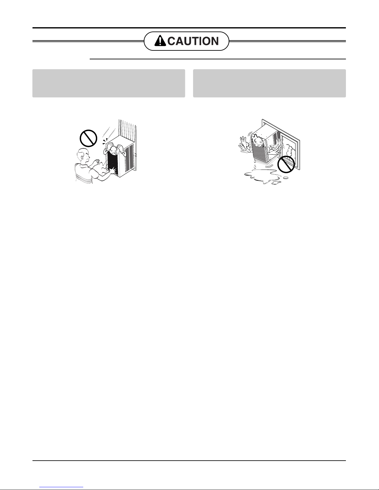
Safety Precautions.....................................................4
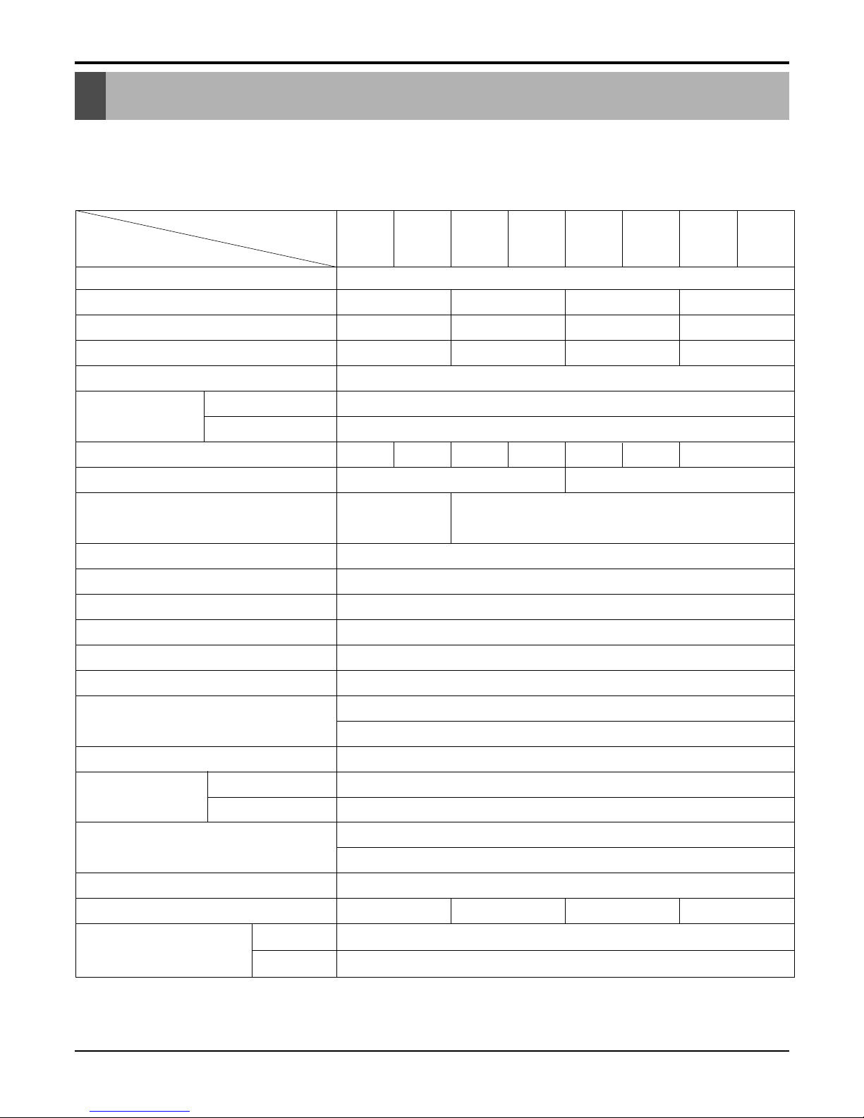
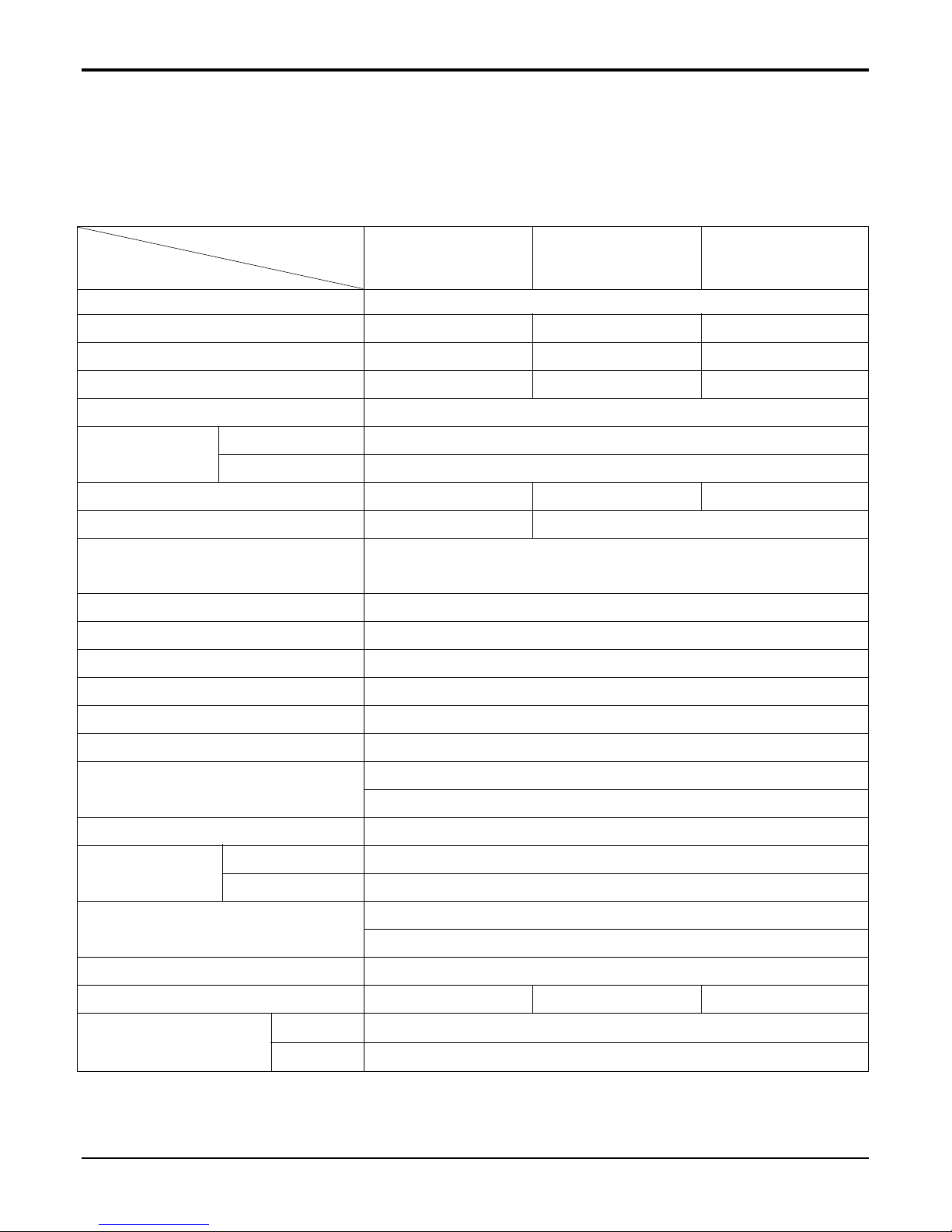
Product Specifications ..............................................6
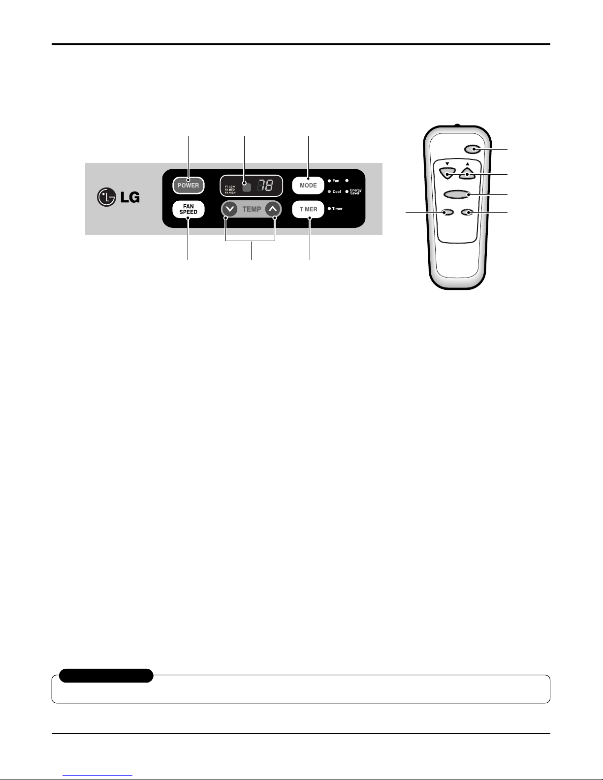
Operation ....................................................................8
Features ..................................................................8
Control Locations ....................................................8
Mechanical type model .......................................8
Electronic type model..........................................9
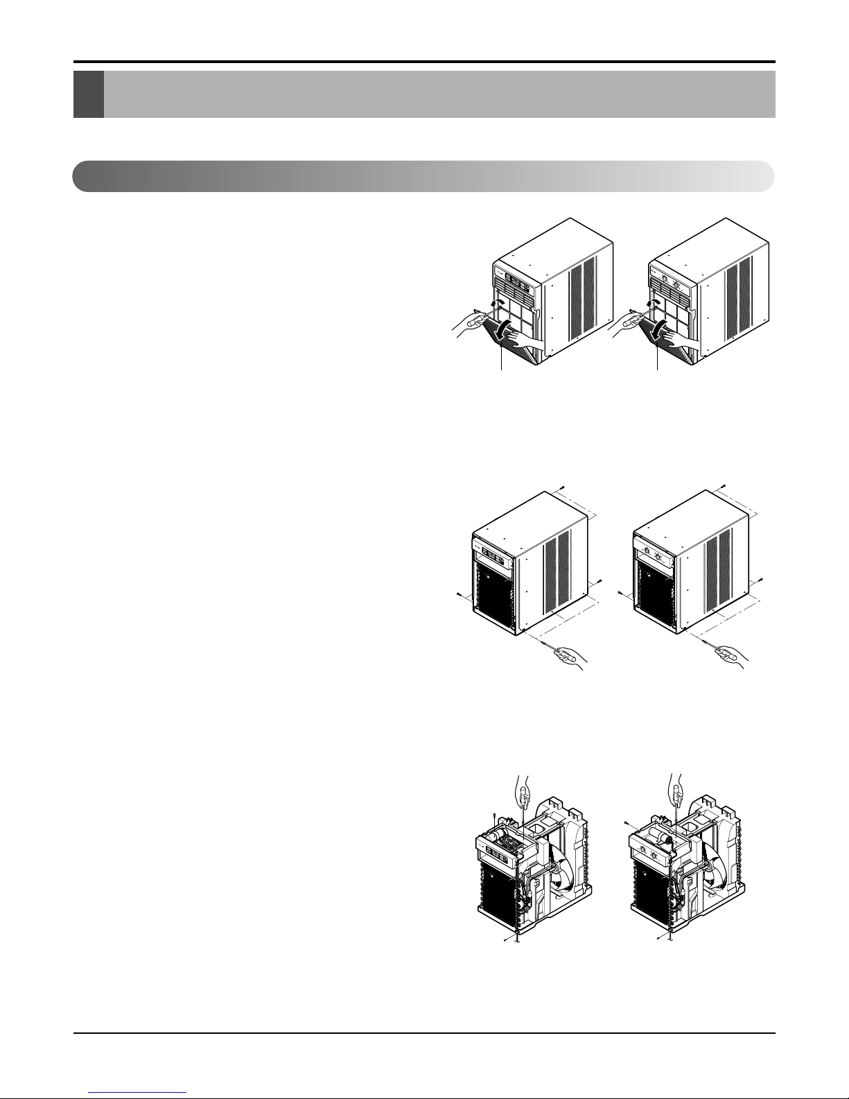
Disassembly Instructions........................................10
Mechanical Parts...................................................10
Front grille .........................................................10
Cabinet..............................................................10
Control box........................................................10
Air Handling Parts .................................................11
Air guide and turbo fan......................................11
Fan ....................................................................11
Shroud ..............................................................12
Electrical Parts ......................................................12
Overload protector ............................................12
Compressor ......................................................12
Capacitor...........................................................13
Power cord ........................................................13
Thermostat........................................................13
Rotary switch ....................................................13
Motor.................................................................14
Refrigerating Cycle................................................14
Condenser ........................................................14
Evaporator.........................................................14
Capillary tube....................................................15
Installation ................................................................17
How to Install the unit ............................................17
Checking installation..............................................17
How to drain ..........................................................17
Window Requirements ..........................................18
Installation Kits Contents.......................................18
Horizontal Sliding Window Installation...................19
Casement Window Installation ..............................20
Troubleshooting Guide ............................................21
Outside dimensions ..............................................21
Piping system ........................................................21
Troubleshooting Guide...........................................22
Room Air Conditioner Voltage Limits.....................29
Mechanical type model .....................................29
Electronic type model........................................29
Schematic Diagram.................................................33
Circuit Diagram......................................................33
Electronic Control Device ......................................38
Components Location
(For Main P.C.B ASM)............................................39
Components Location
(For Display P.C.B ASM)........................................39
Exploded View & Replacement Parts List .............40

This SERVICE MANUAL provides various service information, including the mechanical and electrical parts
etc. This room air conditioner was manufactured and assembled under a strict quality control system.
The refrigerant is charged at the factory. Be sure to read the safety precautions prior to servicing the unit.
1. Unplug the power cord and connect a jumper between 2 pins (black and white).
2. The grounding conductor (green or green and yellow) is to be open.
3. Measure the resistance value with an ohm meter between the jumpered lead and each exposed metallic part on
the equipment at all Mode [except POWER OFF].
4. The value should be over 1MΩ.
1. Unplug the power cord and connect a jumper between 2 pins (black and white).
2. The grounding conductor (green) is to be open.
3. Measure the resistance value with an ohm meter between the jumpered lead and each exposed
metallic part on the equipment at all the positions (except OFF) of the ROTARY SWITCH.
4. The value should be over 1MΩ.
Service Manual 3
Preface
Preface
Electronic Type
Mechanical Type

4Room Air Conditioner
Safety Precautions
Safety Precautions
To prevent injury to the user or other people and property damage, the following instructions must
be followed.
■Incorrect operation due to ignoring instruction will cause harm or damage. The seriousness is
classified by the following indications.
■Meanings of symbols used in this manual are as shown below.
WARNING
CAUTION
This symbol indicates the possibility of death or serious injury.
This symbol indicates the possibility of injury or damage to properties only.
WARNING
■Installation
Be sure not to do.
Be sure to follow the instruction.
Don’t use a power cord, a plug or
a loose socket which is dam-
aged.
• Otherwise, it may cause a fire or
electrical shock.
Always plug into a grounded
outlet.
• Otherwise, it may cause a fire or
electrical shock.
Do not modify or extend the
power cord length.
• It will cause electric shock or fire
due to heat generation.
Do not disassemble or modify
products.
• It may cause failure and electric
shock.
Be caution when unpacking and
installing.
• Sharp edges may cause injury.
Do not use the power cord near flam-
mable gas or combustibles such as
gasoline, benzene, thinner, etc.
• It may cause explosion or fire.
Gasolin

Service Manual 5
Safety Precautions
Install the product so that the noise or hot wind
from the outdoor unit may not cause any damage
to the neighbors.
• Otherwise, it may cause dispute with the neighbors.
Keep level parallel in installing the product.
• Otherwise, it may cause vibration or water leakage.
■Installation

6Room Air Conditioner
Product Specifications
POWER SUPPLY
COOLING CAPACITY (Btu/h)
INPUT (W)
RUNNING CURRENT (A)
E.E.R (BTU/W.h)
INDOOR (°C)
OUTDOOR (°C)
REFRIGERANT (R-22) CHARGE
EVAPORATOR
CONDENSER
FAN, INDOOR
FAN, OUTDOOR
FAN SPEEDS, FAN/COOLING
FAN MOTOR
OPERATION CONTROL
ROOM TEMP. CONTROL
AIR DIRECTION CONTROL
CONSTRUCTION
PROTECTOR COMPRESSOR
FAN MOTOR
POWER CORD
DRAIN SYSTEM
NET WEIGHT (lbs/kg)
OUTSIDE DIMENSION (inch)
(W x H x D) (mm)
115V, 60Hz
6,000 8,000 10,000 12,000
630 840 1,050 1,260
5.8 7.7 9.6 11.5
9.5
26.7(DB)* 19.4(WB)**
35(DB)* 23.9(WB)**
280g(9.9 oz) 300g(10.6 oz) 460g(16.2 oz) 445g (15.7 oz) 530g(18.7 oz) 520g(18.3 oz) 510g(18.0 oz)
2 ROW 16 STACKS, SLIT FIN TYPE 3 ROW 16 STACKS, SLIT FIN TYPE
1 ROW 23 STACKS,
2 ROW 23 STACKS,
SLIT FIN TYPE
LOUVER FIN TYPE
TURBO FAN
AXIAL FAN
2/3
6 POLES
ROTARY SWITCH
THERMOSTAT
VERTICAL LOUVER (RIGHT & LEFT)
HORIZONTAL LOUVER (UP & DOWN)
TOP-DOWN CHASSIS
OVERLOAD PROTECTOR
INTERNAL THERMAL PROTECTOR
3 WIRE WITH GROUNDING
ATTACHMENT PLUG (CORD-CONNECTED TYPE)
DRAIN PIPE SPLASHED BY FAN SLINGER
57/26 66/30 77/35 79/36
141/2x 201/2x 233/5
368 x 521 x 607
LC6000
LEA0610ACL LC6000Y4 LC8000
LEA0810ACL LC8000Y4
LC1000Y3
LEA1010ACLY3
HBLG1000CY3
LC1000Y4 LC1200Y3
LEA1210ACL LC1200Y4
MODELS
ITEMS
OPERATING
CONDITION
FOR
LC6000/LC8000/LC1000Y3/LC1200Y3/LC6000Y4/LC8000Y4/LC1000Y4/LC1200Y4/LEA0610ACL/
LEA0810ACL/LEA1010ACLY3/LEA1210ACL/HBLG1000CY3
* DB:Dry Bulb
**
WB:Wet Bulb

Service Manual 7
Product Specifications
POWER SUPPLY
COOLING CAPACITY (Btu/h)
INPUT (W)
RUNNING CURRENT (A)
E.E.R (BTU/W.h)
INDOOR (°C)
OUTDOOR (°C)
REFRIGERANT (R-22) CHARGE
EVAPORATOR
CONDENSER
FAN, INDOOR
FAN, OUTDOOR
FAN SPEEDS, FAN/COOLING
FAN MOTOR
OPERATION CONTROL
ROOM TEMP. CONTROL
AIR DIRECTION CONTROL
CONSTRUCTION
PROTECTOR COMPRESSOR
FAN MOTOR
POWER CORD
DRAIN SYSTEM
NET WEIGHT (lbs/kg)
OUTSIDE DIMENSION (inch)
(W x H x D) (mm)
115V, 60Hz
8,000 10,000 12,000
840 1,050 1,260
7.7 9.6 11.5
9.5
26.7(DB)* 19.4(WB)**
35(DB)* 23.9(WB)**
300g(10.6 oz) 445g(15.7 oz) 510g(18.0 oz)
2 ROW 16 STACKS, SLIT FIN TYPE
3 ROW 16 STACKS, SLIT FIN TYPE
2 ROW 23 STACKS,
LOUVER FIN TYPE
TURBO FAN
AXIAL FAN
3/3
6 POLES
REMOTE CONTROLLER
THERMISTOR
VERTICAL LOUVER (RIGHT & LEFT)
HORIZONTAL LOUVER (UP & DOWN)
TOP-DOWN CHASSIS
OVERLOAD PROTECTOR
INTERNAL THERMAL PROTECTOR
3 WIRE WITH GROUNDING
ATTACHMENT PLUG (CORD-CONNECTED TYPE)
DRAIN PIPE SPLASHED BY FAN SLINGER
66/30 77/35 79/36
141/2x 201/2x 233/5
368 x 521 x 607
LV080CE LV100CE
HBLG1004C LV120CE
MODELS
ITEMS
OPERATING
CONDITION
FOR
LV080CE/LV100CE/LV120CE/HBLG1004C
* DB:Dry Bulb
**
WB:Wet Bulb

• Designed for COOLING ONLY.
• Powerful and whispering cooling.
• Simple installation and service.
• Low air-intake, top cooled-air discharge.
MECHANICAL TYPE MODEL
•VENTILATION
The ventilation lever must be in the CLOSE position
in order to maintain the best cooling conditions.
When a fresh air is necessary in the room, set the
ventilation lever OPEN position.
The damper is opened and room air is exhausted.
•TEMP
Thermostat will automatically control the temperature
of the room. Select a higher number for a cooler tem-
perature in the room. The temperature is selected by
moving the knob to the desired position.
The 5or 6position is a normal setting for average
conditions.
•MODE
- Turns air conditioner off.
- Med speed fan operation without cooling.
- Low speed fan operation without cooling.
- Cooling with high speed fan operation.
- Cooling with med speed fan operation.
- Cooling with low speed fan operation.
Before using the air conditioner
secure the front grille with two screws
enclosed with the owner’s manual.
1. Open the inlet grille downward and remove the
air filter.
2. Fasten the front grille with screws.
3. Reinstall the air filter.
4. Close the inlet grille.
• Built-in adjustable THERMOSTAT or THERMISTOR
• Washable one-touch filter
• Compact size
• Reliable and efficient rotary compressor is equipped.
NOTICE
8Room Air Conditioner
Operation
Features
Control Locations
VENTCLOSE OPEN
Inlet Grille
Operation

ELECTRONIC TYPE MODEL
Precaution: The Remote Control unit will not function properly if bright light strikes the sensor window of the air conditioner or
if there are obstacles between the Remote Control unit and the air conditioner.
Service Manual 9
Operation
Power
Temp
Fan Speed
Timer Mode
1
2
4
3
5
°CDry
2
6
1
4 5
3
1. POWER
•To turn the air conditioner ON, push this button. To turn the
air conditioner OFF, push the button again.
•This button takes priority over any other button.
•When you first turn it on, the unit is in cool mode, high fan
speed, temperature setting at 22˚C(72˚F).
2. TEMPERATURE SETTING
•Use this button to automatically control the temperature of
the room.
The temperature can be set within a range of 16˚C(60°F) to
30˚C(86°F) by increments of 1˚C(1°F).
3. MODE
- Every time you push this button, it will cycle through the fol-
lowing modes: COOL, ENERGY SAVER, FAN and DRY.
- ENERGY SAVER
•The fan stops when the compressor stops cooling.
Approximately every 3 minutes the fan will turn on and the
unit will check the room air to determine if cooling is need-
ed.
4.
FAN SPEED
•Every time you push this button, it advances the setting as
follows: {High(F3) →Low(F1) →Med(F2) →High(F3)}
5. TIMER
- SHUT-OFF TIME
•You will usually use shut-off time while you sleep.
•With unit running, use Timer to set number of hours until
shut-off.
•For your sleeping comfort, once Time is set, the
Temperature setting will raise 1°C(2°F) after 30 min, and
1°C(2°F) after another 30 min.
•Every time you push Timer button, it advances the Timer
setting as follows: 1 Hour →2 Hours →etc. → 12 Hours
maximum.
- START TIME
•With unit not running, use timer to set number of hours
before unit starts.
•Every time you push Timer button, it advances the Timer
setting as follows: 1 Hour →2 Hours →etc. →12 Hours
maximum.
6. REMOTE CONTROL SENSOR
AUTO RESTART
When power is restored after an electrical power failure, the unit will begin to run at its last setting.

10 Room Air Conditioner
Disassembly Instructions
Disassembly Instructins
FRONT GRILLE
1. Open the inlet grille downward and remove the air
filter.
2. Remove the screws which fasten the front
grille.(See Figure 1)
3. Pull the front grille from the right side.
4. Remove the front grille.(There are 4 hooks.)
5. Re-install the components by referring to the
removal procedure, above.
CABINET
1. After disassembling the FRONT GRILLE, remove
the 6 screws which fasten the cabinet at both
sides.(See Figure 2)
2. Remove the 4 screws which fasten the cabinet at
back.
3. Remove the cabinet.
4. Re-install the components by referring to the
removal procedure, above.
CONTROL BOX
1. Remove the front grille. (Refer to section 2.1.1)
2. Remove the cabinet. (Refer to section 2.1.2)
3. Remove the 1 screw which fasten the power cord.
(See Figure 3)
4. Disconnect the grounding screw from the evapo-
rator channel.
5. Remove the 2 screws which fasten the control
box.(See Figure 3)
6. Remove the housing which connects motor wire
in the control box.
7. Remove three leads which connect compressor.
8. Discharge the capacitor by placing a 20,000 ohm
resistor across the capacitor terminals.
9. Raise the control box upward completely.
10. Re-install the components by referring to the
removal procedure, above.
(Refer to the circuit diagram found on pages
29~32 in this manual and on the control box.)
Inlet GrilleInlet Grille
—Before the following disassembly, set POWER SWITCH to OFF and disconnect the power cord.
Figure 1
Figure 3
Figure 2
Mechanical Parts

Service Manual 11
Disassembly Instructins
AIR GUIDE AND TURBO FAN
1. Remove the front grille. (Refer to section 2.1.1)
2. Remove the cabinet. (Refer to section 2.1.2)
3. Remove the control box. (Refer to section 2.1.3)
4. Remove the 4 screws which fasten the brace.
5. Remove the brace.
6. Remove the 2 screws which fasten the upper air
guide. (See Figure 4)
7. Remove the upper air guide.
8. Remove the 2 screws which fasten the evapora-
tor.
9. Move the evaporator forward and pulling it upward
slightly. (See Figure 5)
10. Remove orifice by pulling two taps.
11. Remove the clamp with a hand plier which
secures the turbo fan.
12. Remove the turbo fan. (See Figure 6)
13. Remove the motor. (Refer to section 2.3.7)
14. Remove the 2 screws which fasten the lower air
guide from the base pan.
15. Remove the 2 screws which fasten the motor
mount from the base pan.
16. Remove the 2 screws which fasten the lower air
guide and motor mount.
17. Move the lower air guide backward and pull out
from the base pan. (Move the lower air giude
carefully.)
18. Re-install the components by referring to the
removal procedure, above.
FAN
1. Remove the cabinet. (Refer to section 2.1.2)
2. Remove the brace (Refer to section 2.2.1)
3. Remove 6 screws which fasten the condenser.
4. Move the condenser to the right carefully.
5. Remove the clamp with a hand plier which secures the
fan.
6. Remove the fan. (See Figure 7)
7. Re-install by referring to the removal procedure.
Figure 4
Figure 5
Figure 6
Figure 7
Air Handling Parts

12 Room Air Conditioner
Disassembly Instructins
SHROUD
1. Remove the fan. (Refer to section 2.2.2)
2. Remove the shroud. (See Figure 8)
3. Re-install the components by referring to the
removal procedure, above.
OVERLOAD PROTECTOR
1. Remove the cabinet. (Refer to section 2.1.2)
2. Remove the nut which fastens the terminal cover.
3. Remove the terminal cover. (See Figure 9)
4. Remove all the leads from the overload protector.
5. Remove the overload protector.
6. Re-install the components by referring to the
removal procedure, above.
COMPRESSOR
1. Remove the cabinet. (Refer to section 2.1.2)
2. Discharge the refrigerant system using a FreonTM
Recovery System.
If there is no valve to attach the recovery system,
install one (such as a WATCO A-1) before venting
the FreonTM. Leave the valve in place after
servicing the system.
3. Remove the overload protector. (Refer to section
2.3.1)
4. After purging the unit completely, unbraze the suc-
tion and discharge tubes at the compressor con-
nections.
5. Remove the 3 nuts and the 3 washers which
fasten the compressor.
6. Remove the compressor. (See Figure 10)
7. Re-install the components by referring to the
removal procedure, above.
Figure 8
Figure 9
Figure 10
Electrical Parts

Service Manual 13
Disassembly Instructins
CAPACITOR
1. Remove the cabinet. (Refer to section 2.1.2)
2. Remove the screw and the clamp which fastens the
capacitor.
3. Disconnect all the leads of capacitor terminals.
4. Re-install the components by referring to the
removal procedure, above. (See Figure 11)
POWER CORD
1. Remove the cabinet. (Refer to section 2.1.2)
2. Disconnect the grounding screw from the control
box.
3. Disconnect the 2 receptacles.
4. Remove a screw which fastens the clip cord.
(See Figure 12)
5. Remove the power cord.
6. Re-install the component by referring to the above
removal procedure, above.
(Use only one ground-marked hole for ground
connection.)
7. If the supply cord of this appliance is damaged, it
must be replaced by the special cord. (The
special cord means the cord which has the same
specification marked on the supply cord attached at
the unit.)
THERMOSTAT(For Mechanical Type)
1. Remove the cabinet. (Refer to section 2.1.2)
2. Remove the 2 screws which fasten the thermostat.
3. Disconnect 2 leads of thermostat terminals.
4. Remove the thermostat.
5. Re-install the components by refering to the above
removal procedure. (See Figure 13)
THERMOSTAT(For Electronic Type)
1. Plug out thermistor from the main PCB.
ROTARY SWITCH
1. Remove the cabinet. (Refer to section 2.1.2)
2. Remove the 2 screws which fasten the rotary
switch.
3. Disconnect all the leads of the rotary switch termi-
nals.
4. Remove the rotary switch.
5. Re-install the components by referring to the
above removal procedure. (See Figure 14)
Figure 11
Figure 12
Figure 13
Figure 14
Mechanical Type
Electronic Type

MOTOR
1. Remove the cabinet. (Refer to section 2.1.2)
2. Remove the turbo fan. (Refer to section 2.2.1)
3. Remove the fan. (Refer to section 2.2.2)
4. Remove the 4 screws which fasten the motor from
the Motor Mount. (See Figure 15)
5. Remove the motor.
6. Re-install the components by referring to the
removal procedure, above.(See Figure 15)
CONDENSER
1. Remove the cabinet. (Refer to section 2.1.2)
2. Remove the 4 screws which fasten the brace.
3. Remove the 4 screws which fasten the condenser
and shroud. (See Figure 16)
4. Remove the 2 screws which fasten the condenser
and base pan.
5. After discharging the refrigerant completely,
unbraze the interconnecting tube at the condenser
connections.
6. Remove the condenser.
7. Re-install the components by referring to notes.
(See Figure 16)
EVAPORATOR
1. Remove the cabinet. (Refer to section 2.1.2)
2. Remove the control box.(Refer to section 2.1.3)
3. Remove the upper air guide. (Refer to section
2.2.1)
4. Remove the 2 screws which fasten the evaporator
from lower air guide.
5. Move the evaporator sideways carefully.
(Refer to section 2.2.1)
6. After discharging the refrigerant completely,
unbraze the interconnecting tube at the evaporator
connections.
7. Remove the evaporator.
8. Re-install the components by referring to notes.
(See Figure 17)
14 Room Air Conditioner
Disassembly Instructins
Refrigerating Cycle
Figure 15
Figure 16
Figure 17
Discharge the refrigerant system using a
FreonTM Recovery System.
If there is no valve to attach the recovery
system, install one (such as a WATCO A-1)
before venting the FreonTM. Leave the valve in
place after servicing the system.
CAUTION

Service Manual 15
Disassembly Instructins
—Replacement of the refrigerant.
1. When replacing the refrigerant, be sure to
Discharge the refrigerant system using a FreonTM
recovery System.
If there is no valve to attach the recovery system,
install one (such as a WATCO A-1) before venting
the FreonTM. Leave the valve in place after
servicing the system.
2. After discharging the unit completely, remove the
desired component, and unbraze the pinch-off
tubes.
3. Solder service valves into the pinch-off tube ports,
leaving the valves open.
4. Solder the pinch-off tubes with Service valves.
5. Evacuate as follows.
1) Connect the vacuum pump, as illustrated figure
18A.
2) Start the vacuum pump, slowly open manifold
valves A and B with two full turns counterclock-
wise and leave the valves open.
The vacuum pump is now pulling through valves
A and B up to valve C by means of the manifold
and entire system.
3) Operate the vacuum pump for 20 to 30 minutes,
until 600 microns of vaccum is obtained. Close
valves A and B, and observe vacuum gauge for
a few minutes. A rise in pressure would
indicate a possible leak or moisture remaining in
the system. With valves A and B closed, stop
the vacuum pump.
4) Remove the hose from the vacuum pump and
place it on the charging cylinder. See figure
18B.
Open valve C.
Discharge the line at the manifold connection.
5) The system is now ready for final charging.
6. Recharge as follows :
1) Refrigeration cycle systems are charged from
the High-side. If the total charge cannot be put
in the High-side, the balance will be put in the
suction line through the access valve which you
installed as the system was opened.
2) Connect the charging cylinder as shown in figure
18B.
With valve C open, discharge the hose at the
manifold connection.
3) Open valve A and allow the proper charge to
enter the system. Valve B is still closed.
4) If more charge is required, the high-side will not
take it. Close valve A.
5) With the unit running, open valve B and add the
balance of the charge.
a. Do not add the liquid refrigerant to the Low-
side.
b. Watch the Low-side gauge; allow pressure to
rise to 30 lbs.
c. Turn off valve B and allow pressure to drop.
d. Repeat steps b. and c. until the balance of the
charge is in the system.
6) When satisfied the unit is operating correctly,
use the pinch-off tool with the unit still running
and clamp on to the pinch-off tube. Using a tube
cutter, cut the pinch-off tube about 2 inches from
the pinch-off tool. Use sil-fos solder and solder
pinch-off tube closed. Turn off the unit, allow it to
set for a while, and then test the leakage of the
pinch-off connection.
NOTES
If high vacuum equipment is used, adjust valves
A and B so they are opened only slightly for a few
minutes, then open slowly with the two full turns
counterclockwise. This will keep oil from foaming
and being drawn into the vacuum pump.
CAPILLARY TUBE
1. Remove the cabinet. (Refer to section 2.1.2)
2. After discharging the refrigerant completely,
unbraze the interconnecting tube at the capillary
tube.(See caution above)
3. Remove the capillary tube.
4. Re-install the components by referring to notes.
CAUTION

16 Room Air Conditioner
Disassembly Instructins
Equipment needed: Vacuum pump, Charging cylinder, Manifold gauge, Brazing equipment. Pin-off tool capable
of making a vapor-proof seal, Leak detector, Tubing cutter, Hand Tools to remove components, Service valve.
A
COMPOUND GAUGE
EVAPORATOR
(LOW PRESSURE SIDE)
COMPRESSOR
CAPILLARY TUBE
CONDENSER
(HIGH PRESSURE SIDE)
SEE INSETS
BELOW
MANIFOLD
GAUGE
B
Figure 18A-Pulling Vacuum Figure 18B-Charging
A
B
EXTERNAL
VACUUM PUMP
A
CHARGING
CYLINDER
LOW HI
B
C

Service Manual 17
Installation
HOW TO INSTALL THE UNIT
1. To avoid vibration and noise, make sure the unit is
installed securely and firmly.
2. Install the unit where the sunlight does not shine directly
on the unit.
If the unit receives direct sunlight, build an awning to
shade the cabinet.
3. There should be no obstacle, like a fence, within 20"
which might restrict heat radiation from the condenser.
4. To prevent reducing performance, install the unit so that
louvers of the cabinet are not blocked.
5. Install the unit a little obliquely outward not to leak the
condensed water into the room (about 1/4").
6. Install the unit with its bottom portion 30~60" above the
floor level.
7. Stuff the foam between the top of the unit and the wall to
prevent air and insects from getting into the room.
8. The power cord must be connected to an independent
circuit. The green wire must be grounded.
9. Connect the drain tube to the base pan hole in the rear
side if you need to drain (consult a dealer).
Plastic hose or equivalent may be connected to the drain
tube.
CHECKING INSTALLATION
The setting conditions must be checked prior to ini-
tial starting.
The items mentioned below are especially impor-
tant checking points when the installation is fin-
ished.
1. Grounding wire (Green or Green and Yellow) is
provided in the power cord. The green wire must
be grounded.
2. Connect to a single-outlet 15A circuit.
3. To avoid vibration or noise, make sure the air con-
ditioner is installed securely.
4 Avoid placing furniture or draperies in front of the
air inlet and outlet.
HOW TO DRAIN
(When using drain pipe)
The air conditioner must be installed horizontally or
tilted slightly to the outside for proper water
drainage.
On exceptionally hot and humid days the air condi-
tioner may overflow condensed water.
If the air conditioner is used in hot and a high
humidity zone, exchange the DRAIN CAP for the
DRAIN PIPE.(See Figure 20, Figure 21)
About 1/4"
30"~60"
Awning
Cooled air
Fence
Over 20"
Heat
radiation
BOTTOM
DRAIN CAP
1
BASE PAN
BOTTOM
DRAIN PIPE
2
BASE PAN
Figure 20
Figure 21
Figure 19
Installation

18 Room Air Conditioner
WINDOW REQUIREMENTS
1. These instructions are for a horizontal sliding or a
casement window.
2. The electrical outlet must be within reach of the
power cord.
For installation in a casement window, the window
frame assembly and the side of the building must be
adequate to support the weight of the air conditioner.
INSTALLATION KITS CONTENTS
21" min.
40 1/2" max.
15 1/2"
min.
Horizontal sliding window
21 1/2" min.
15 1/2" min.
16 1/2" max.
Casement window
Nut (2) Washer (2) Type A (9) Type B (3) Type C (8)
Bolt (2)
CurtainWindow Locking
Bracket
Side Guide
Support Bracket
Leveling
bolt & nut
Bracket
Side Guide
Upper Guide
Curtain Frame
Side Guide SealFoam Seal Strip
Window Track Seal
Installation

Service Manual 19
Installation
1. Loosely attach the Support Bracket to the bottom of
Bracket using Bolts, Washers, and Nuts. Attach the
Leveling bolt and nut. (See Figure 22)
2. Remove protective backing from Window Track Seal
and apply seal to window track. (See Figure 23)
3. Measure and lightly mark a line 8-1/4 inches from win-
dow jamb. Center the Support Bracket assembly on
the window track and fasten with 4 Type C screws.
(See Figure 23)
4. Put the Support Bracket against the outside wall and
tighten the Bolts on top of the Bracket. Adjust the
Leveling Bolt so that the air conditioner will be
installed with a very slight tilt (about 1/4") downward
toward the outside for proper drainage.
Tighten the nut. (See Figure 24)
NOTE: DO NOT drill a hole in the bottom of the base
pan. The air conditioner is designed to operate
with the bottom of the base pan approximately
half-full of water.
5. Fasten Side Guides to the sides of the Air Conditioner
using 3 Type A screws per Guide. Start with first
screw at middle of Guide. (See Figure 25)
6. Fasten Upper Guide on the top of the Air Conditioner
using 3 Type A screws. (See Figure 25)
7. Measure height of window opening from top of
Bracket assembly as shown Fig. 26.
Subtract 20-3/4 inches. Mark this measurement on
Curtain and cut the Curtain. (See Figure 26)
81111/1616 inches811/16 inches
Window Track
Window Track
Seal
Fastening Side Guides
Upper Guide
Side Guide
Window jambWindow jamb
Type C screwType C screw
Outside Wall
Bracket
Support Bracket
Nut
Washer
Leveling Bolt & Nut
Bolt
about 1/4"
Figure 22
Figure 23
Figure 24
Figure 25
Figure 26
HORIZONTAL SLIDING WINDOW INSTALLATION

20 Room Air Conditioner
Installation
8. Slide Curtain into Curtain Frame. Slide Curtain Frame
assembly into side Guides of the Air Conditioner cabi-
net. Make sure Curtain is firmly enclosed on all sides
by the Frame. (See Figure 27)
9. Cut side Guide seal into 2 equal lengths. Remove pro-
tective backing and apply it to the rear side of cabinet
Side Guides, starting just below Curtain Frame
assembly. Pinch off excess length so seal is even with
the bottom of side Guide. (See Figure 28)
10. Place Air Conditioner in window opening. It should sit
on Bracket assembly so that Curtain Frame and cab-
inet Side Guides are against top and side window
jambs. Mate front of Bracket with Base Guide
attached to the bottom of base pan.
11. Drill 1/8 inch holes in window track through the exist-
ing holes on Base Guide. Screw 4 Type C screws
through the holes. (See Figure 29)
12. If this is a casement window installation, proceed to
Casement Window Installation. If not, slide inner win-
dow sash firmly against side of the cabinet.
13.
Drill 1/8 inch hole in window jamb to align with the
existing holes in the Curtain Frame. Attach Curtain
Frame to window frame with 2 Type B screws.
(See
Figure 29)
NOTE: Check all seals and plug any remaining air gaps
with a suitable weatherproof caulk.
14. If this is a casement window installation, proceed to
Casement Window Installation. If not, stuff the Foam
Seal Strip between the vertical sash and the window
glass.
(See Figure 30)
15. Attach the Window Locking Bracket with a Type B
screw.
(See Figure 30)
CASEMENT WINDOW INSTALLATION
•Installation procedure is the same as that described in
steps 1 through 11 and step 13 of the Horizontal
Sliding Window installation.
•If the window opening is wider than 15-3/4 inches you
will need to install a filler panel. Make this panel from
3/4 inch thick wood and run it the full length of the win-
dow. Attach it securely to the window frame and paint it
to protect it from the weather.
•Since styles and sizes of casement windows vary wide-
ly, it is advisable to have the air conditioner installed by
someone skilled in this type of installation.
Curtain Frame
Curtain
Window
locking
bracket
Foam seal strip
Apply weather seal
to side guides
just below edge of
Curtain Frame.
Type B screwType B screw
Type C screw
Base panBase pan
BracketBracket
Window TrackWindow Track
Base GuideBase Guide
Figure 27
Figure 28
Figure 29
Figure 30
This manual suits for next models
16
Table of contents
Other LG Air Conditioner manuals
Popular Air Conditioner manuals by other brands

Mitsubishi Electric
Mitsubishi Electric MFZ-KJ50VE operating instructions

Mitsubishi Electric
Mitsubishi Electric Mr. Slim PSA-RP KA Series Operation manual

BorMann
BorMann Elite BFN5610 manual

Amana
Amana AHQ246 installation instructions

Midea
Midea MCA-24HRN2MCA-24CRN2 installation manual

Fujitsu
Fujitsu Inverter Halcyon ASU9RMLQ Service manual