Note : 1. Capacities are based on the following conditions:
Cooling: - Indoor Temperature 27.0 (80.6°F ) DB/19.0 (66.2°F) WB
- Outdoor Temperature 35 (95°F) DB/24 (75.2°F) WB
Piping Length - Interconnecting Piping Length 7.5m
'- Level Difference of Zero
2. Nominal CFM : Fan operation mode with clean filter, dry coil.
3. The specification may be subject to change without prior notice for purpose of improvement.
Conversion Formula
kcal/h = kW x 860
Btu/h = kW x 3412
cfm = m 3/min x 35.3
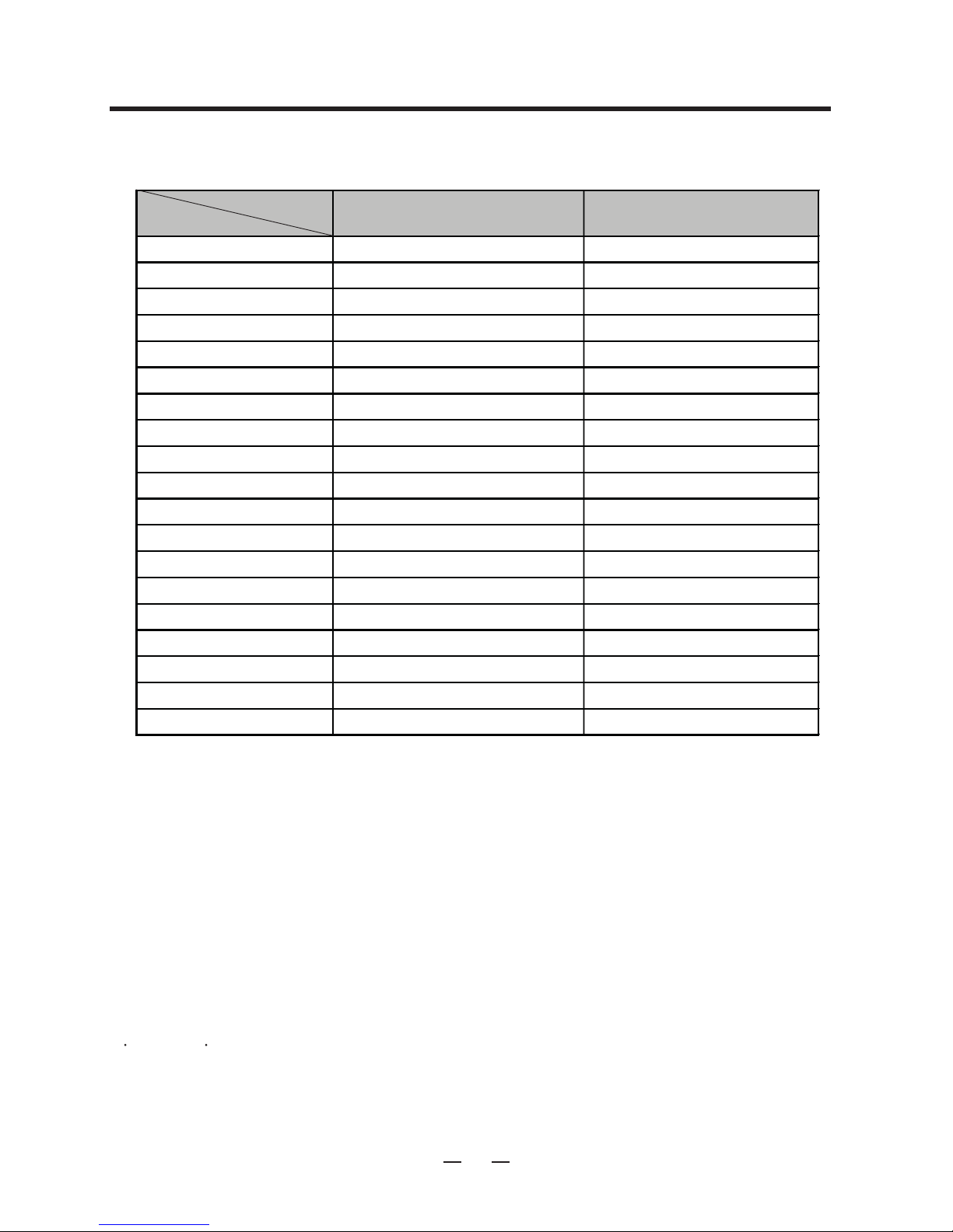
(RT) 20
TN-C240BT00
kW 53.54 70.41
Btu/h 182 700 240 239
kW 52.75 67.41
Btu/h 180 000 230 000
kW - -
Btu/h - -
Ø / V / Hz 3/220ѝѝ
Cooling A 76
Heating A - -
Cooling W 22 000 2
Heating W - -
CFM 5 300 7 500
Btu/h.W 8.18 9.02
Btu/h.W - -
W/W - -
bell+3 67 6
bell+3
High efficiency High efficiency
mm(inch) 9.52(3/8) 9.52(3/8)
3R / 30C / 17FPI 3R / 30C / 17FPI
mm(inch) 1500(59 17/32) 1500(59 17/32)
༇
1.14(12.33) 1.14(12.33)
Centrifugal Blower Centrifugal Blower
mm(inch) 393(15 15/32) 393(15 15/32)
mm(inch) 557(21 15/16) 557(21 15/16)
WEITELI WEITELI
Belt/1 Belt/1
11
Hp 4.0/6.0 4.0/6.0
1 0/ 1 0 1 0/ 1 0
11
SCROLL * 4 SCROLL * 4
Btu/h 49 500 62 000
W 4625 5538
SUNISO 4GSI SUNISO 4GSI
cc 1800 1950
High efficiency High efficiency
mm(inch) 9.52(3/8) 9.52(3/8)
3R / 40C / 14FPI*2 3R / 40C / 14FPI*2
mm(inch) - -
༇
0.50 0.50
Propeller * 2 Propeller * 2
inch - -
--
Direct Direct
CFM 8200 8200
Hp 2EA / 1.5 2EA / 1.5
90 90
mm(inch) 15.88(5/8) 15.88(5/8)
mm(inch) 28(9/8) 28(9/8)
mm(inch) 15.88(5/8) 15.88(5/8)
mm(inch) 28(9/8) 28(9/8)
m(inch) 7.5(295 9/32) 7.5(295 9/32)
˜
/h 17 17
1 1/4 1 1/4
kg 7.5*2 7.6*2
lbs - -
Type R22 R22
Capillary Tube Capillary Tube
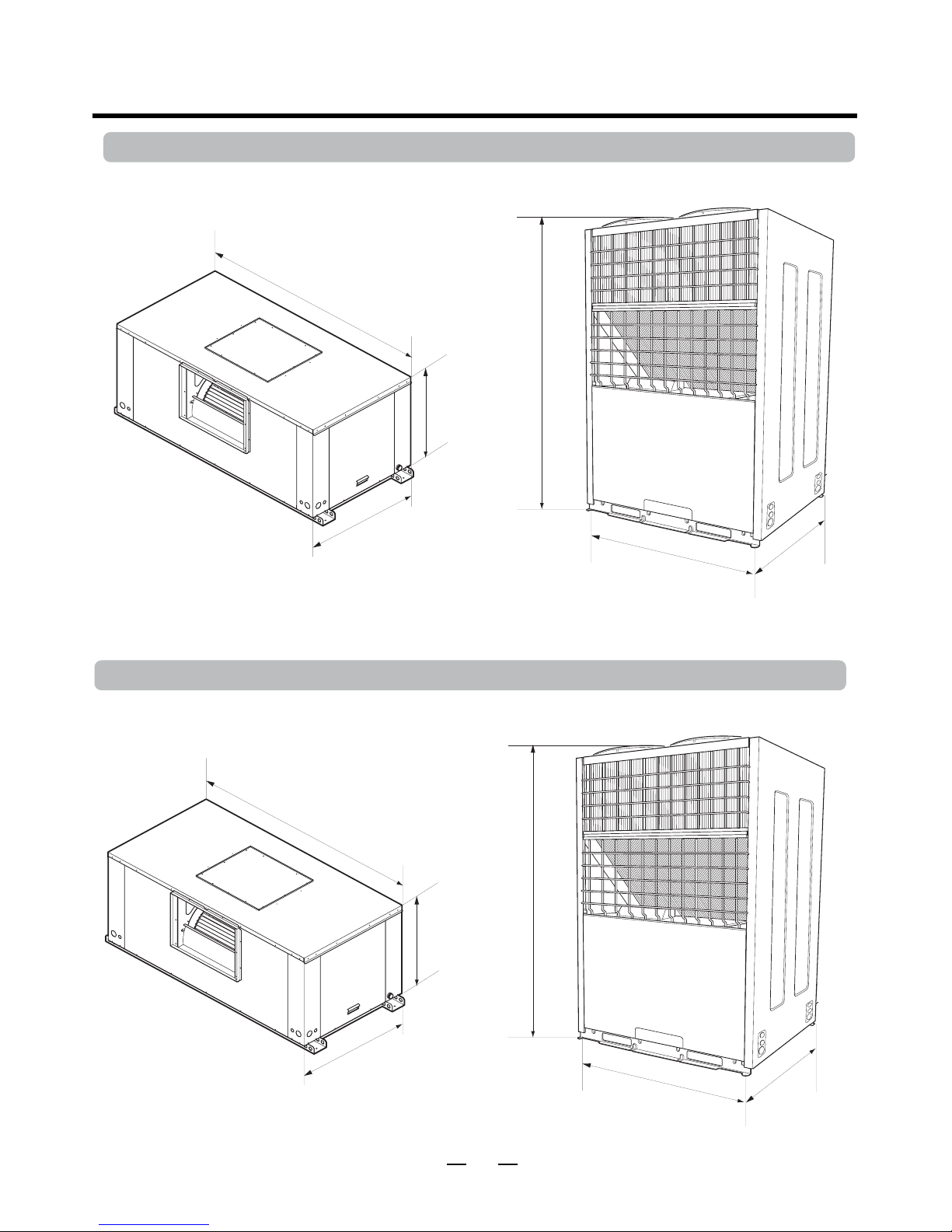
mm 1800*890*1000 1800*890*1000
inch 70 7/8* 35 3/8 *39 3/8 70 7/8* 35 3/8 *39 3/8
mm 1560*1100*880 1760*1100*970
inch 61 7/16* 43 5/16 * 34 5/8 69 1/4* 43 5/16 * 38 3/16
kg(lbs) 250˄550˅250˄550˅
kg(lbs) 340(748) 340(748)
--
inch - -
Outdoor Unit or S/Package
Dimensions
Indoor Unit (W * H * D)
Refrigerant Refrigerant Charge
Refrigerant Control
Service Valve Liquid
Gas
Outdoor Motor
No. Motor / Motor Output(Hp)
Air Circulation
Drive Type
Maker
Outdoor Fan Type * No. Used
Diameter
Length
Face Area
Tube Size(O.D)
Rows / Column / FPI
No. of Outdoor Units
Motor Output(Standard / Oversized)
No. Motors
Drive Type / Motor Step
Width
Indoor Fan
Type * No. Used
Length
Tube Size(O.D)
Sound Rating˄outdoor˅
Sound Rating˄indoor˅
SEER
Performance
Air Circulation(Nominal)
COP
EER
Power Input
M.C.A
(with Standard Motor)
TN-C180BT00
15
Outdoor Unit
(W * H * D)
Net Weight Indoor Unit
Fliter Size * No. Used
Filter Rack Thickness
Length(Standard)
Connecting Pipe
Motor RPM
Compressor
Motor Input
Oil Type
Oil Charge
Condenser
Drain Connection Size(inch)
Liquid
Gas
Dehumidification Rate
Type
Type * Quantity
Model
Maker
Capacity
Motor Type
Electrical Data
Power Supply
Indoor Motor
Maker
Diameter
Evaporator
Type
Rows / Column / FPI
Face Area
Motor RPM(Standard / Oversized)
Nominal RT
Models
Gross Cooling Capacity
Net Cooling Capacity
Capacity
Net Heating Capacity
9
75 75
240/60 3/220 240/60
SR049RAC SR061RBA
LG LG
One Phase One Phase
140
5 500
72 73 72 73
77
General Data
6


 User manual")


 null")