4Multi Air Conditioner
Safety Precautions
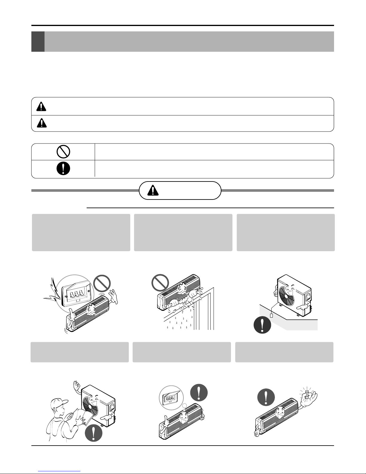
■Operational
Do not modify or extend the
power cable.
• There is risk of fire or electric shock.
Do not install, remove, or re-
install the unit by yourself
(customer).
• There is risk of fire, electric shock,
explosion, or injury.
Be cautious when unpacking
and installing the product.
• Sharp edges could cause injury. Be
especially careful of the case edges
and the fins on the condenser and
evaporator.
For installation, always con-
tact the dealer or an
Authorized Service Center.
• There is risk of fire, electric shock,
explosion, or injury.
Do not install the product on a
defective installation stand.
• It may cause injury, accident, or dam-
age to the product.
Be sure the installation area
does not deteriorate with age.
• If the base collapses, the air condition-
er could fall with it, causing property
damage, product failure, and personal
injury.
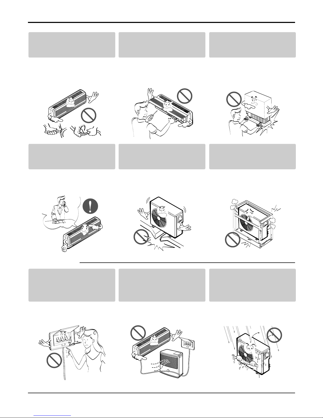
Do not touch(operate) the
product with wet hands.
• There is risk of fire or electrical shock.
Do not place a heater or other
appliances near the power
cable.
• There is risk of fire and electric shock.
Do not allow water to run into
electric parts.
• It may cause There is risk of fire, fail-
ure of the product, or electric shock.


 null")