–6–
Item Unit
Cooling Capacity kcal/h(W)
BTU/h
Heating Capacity kcal/h(W)
BTU/h
Input Cooling/Heating W
Running Current Cooling/Heating A
Starting Current Cooling/Heating A
E.E.R Cooling kcal/hW(W/W)
BTU/hW
C.O.P Heating kcal/hW(W/W)
BTU/hW
Power Supply Ø,V,Hz
Power Factor %
RPM Cooling(H/M/L) rpm
Heating(H/M/L) rpm
Outdoor rpm
Air Circulation Indoor(H/M/L) m3/min
Outdoor m3/min
External static pressure mmAq(Pa)
Moisture Removal l/h
Noise Level Indoor(H/M/L) dB(A)
(Sound Press,1m) Outdoor Max dB(A)
Drain hose In/Out diameter mm
Drain connection size(in/out) inch
Main cable No.X mm2
Connecting Cable No.X mm2
Refrigerant Control Type
Refrigerant(R-22) charge g
Compressor Locked Rotor Amp. A
Type
Model
Maker
Capacity kcal/h(BTU/h)
Motor Type
Motor Input W
Oil Type
Oil Charge CC
PTCR Ω
O.L.P Type(model name)
Indoor motor Type
Model
No. of Poles
Input W
Current A
Capacitor µF/Vac
Outdoor motor Type
Model
Input W
Current A
No. of Poles
Capacitor µF/Vac
SVC Valve Liquid inch(mm)
Gas inch(mm)
Connecting Tube Liquide Side inch(mm)
(ø. Socket Flare) Gas Side inch(mm)
Length, std m
Max length(elevation)
m
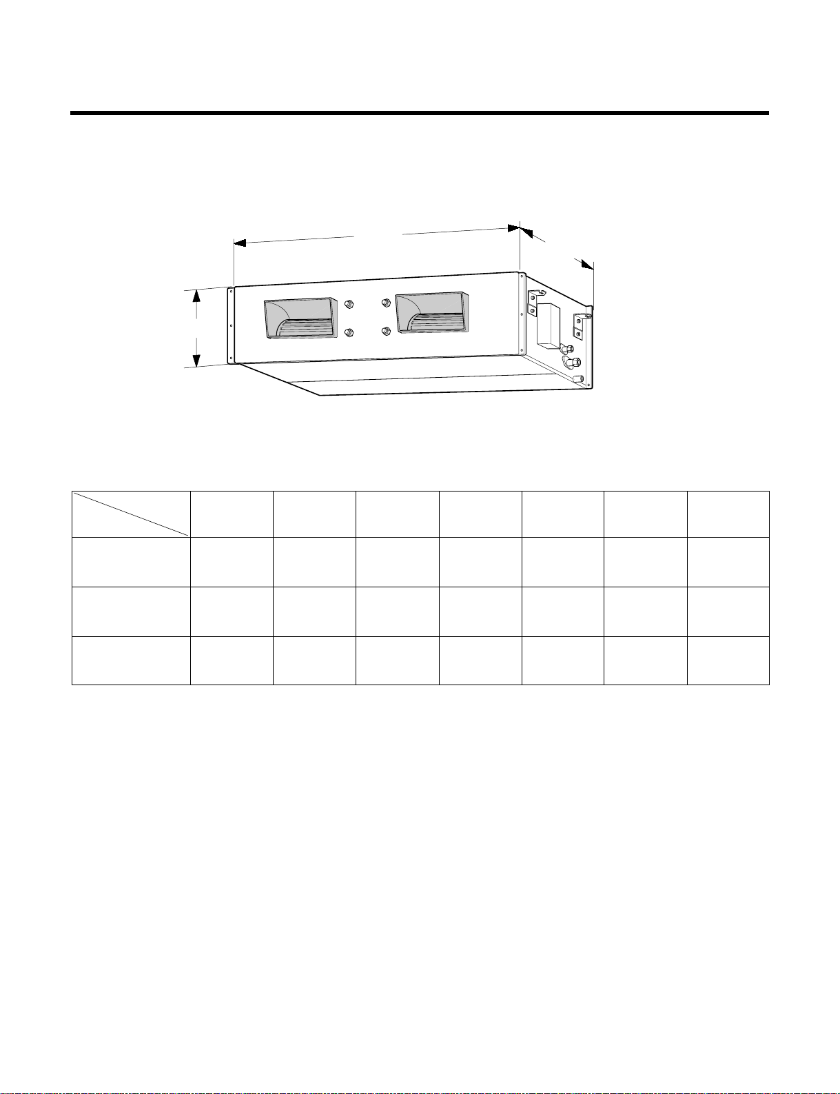
Dimensions (WXHXD) Indoor mm(inch)
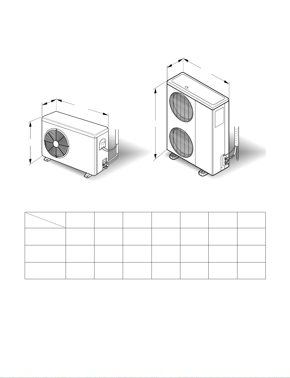
Outdoor mm(inch)
Net Weight indoor kg(lbs)
Outdoor kg(lbs)
Stuffing Quantity With(Without)S/Parts 20/40ft
LB-F3061HL/F3063HL LB-F3661CL/F3663CL LB-F3661HL/F3663HL LB-F3681CL/F3683CL
7,560/8,790 9,072/10,548 9,072/10,548 9,072/10,548
30,000 36,000 36,000 36,000
7,560/8,790 - 9,072/10,548 -
30,000 - 36,000 -
3,000/2,500 4,400/- 4,400/3,600 4,000/-
14/12 20/- 20/20 8/-
110/110 125/- 125/125 45/-
2.52(2.93) 2.17(2.52) 2.17(2.52) 2.39(2.78)
10.0 8.6 8.6 9.5
3.01(3.5) - 2.67(3.1) -
11.95 - 10.58 -
1,220-240,50 1,220-240,50 1,220-240,50 1,380-415,50
96 96 96 91
1,330/1,276/1,213 1,330/1,276/1,213 1,330/1,276/1,213 1,330/1,276/1,213
1,330/1,276/1,213 - 1,330/1,276/1,213 -
930 940 940 940
31.5/29/25 31.5/29/25 31.5/29/25 31.5/29/25
49 52 52 52
10(100) 10(100) 10(100) 10(100)
3.50 4.50 4.50 4.50
42/40/38 42/40/38 42/40/38 42/40/38
56 56 56 56
22.6/25.4 22.6/25.4 22.6/25.4 22.6/25.4
0.89/1 0.89/1 0.89/1 0.89/1
3*3.5 3*5.5 3*5.5 4*2.5
5*0.75 4*0.75 5*0.75 4*0.75
Capillary Type Capillary Type Capillary Type Capillary Type
2,600 2,850 2,850 2,800
110 125 125 45
RECIPROCATING RECIPROCATING RECIPROCATING RECIPROCATING
H25B35QABHA CR47K6-PFZ CR47K6-PFZ CR47K6-TFD
BRISTOL COPELAND COPELAND COPELAND
7,560(30,000) 10,558(41,900) 10,558(41,900) 10,634(42,200)
psc psc psc psc
2,780 4,340 4,340 4,290
SUNISO 3GS SONTEX 200LT SONTEX 200LT SUNISO 3GS
1,180 1,627 1,627 1,627
20 20 20 -
Internal Internal Internal Internal
Condenser inducted Condenser inducted Condenser inducted Condenser inducted
IC-13470LGDM IC-13470LGDM IC-13470LGDM IC-13470LGDM
44 4 4
353 353 353 353
1.65 1.65 1.65 1.65
10/370 10/370 10/370 10/370
Condenser inducted Condenser inducted Condenser inducted Condenser inducted
AMR-070B6 AMR032E6 AMR032E6 AMR032E6
151 151 151 151
0.35 0.62 0.62 0.62
64 4 4
6/370 2/400 2/400 2/400
3/8(9.52) 3/8(9.52) 3/8(9.52) 3/8(9.52)
5/8(15.88) 5/8(15.88) 5/8(15.88) 5/8(15.88)
3/8(9.52) 3/8(9.52) 3/8(9.52) 3/8(9.52)
5/8(15.88) 5/8(15.88) 5/8(15.88) 5/8(15.88)
7.5 7.5 7.5 7.5
50(30) 50(30) 50(30) 50(30)
1,180*600*298(46.46*23.62*11.73) 1,180*600*298(46.46*23.62*11.73) 1,180*600*298(46.46*23.62*11.73) 1,180*600*298(46.46*23.62*11.73)
870*320*800(34.25*12.60*31.5) 790*320*965(31.10*12.6*37.99) 790*320*965(31.10*12.6*37.99) 790*320*965(31.10*12.6*37.99)
46(101.3) 46(101.3) 46(101.3) 46(101.3)
55(121.2) 78(171.8) 78(171.8) 78(171.8)
32/71(32/71) 34/72(34/72) 34/72(34/72) 34/72(34/72)


 null")