2Room Air Conditioner
Air Conditioner Service Manual
TABLE OF CONTENTS
Safety Precautions..........................................................................................................................................3
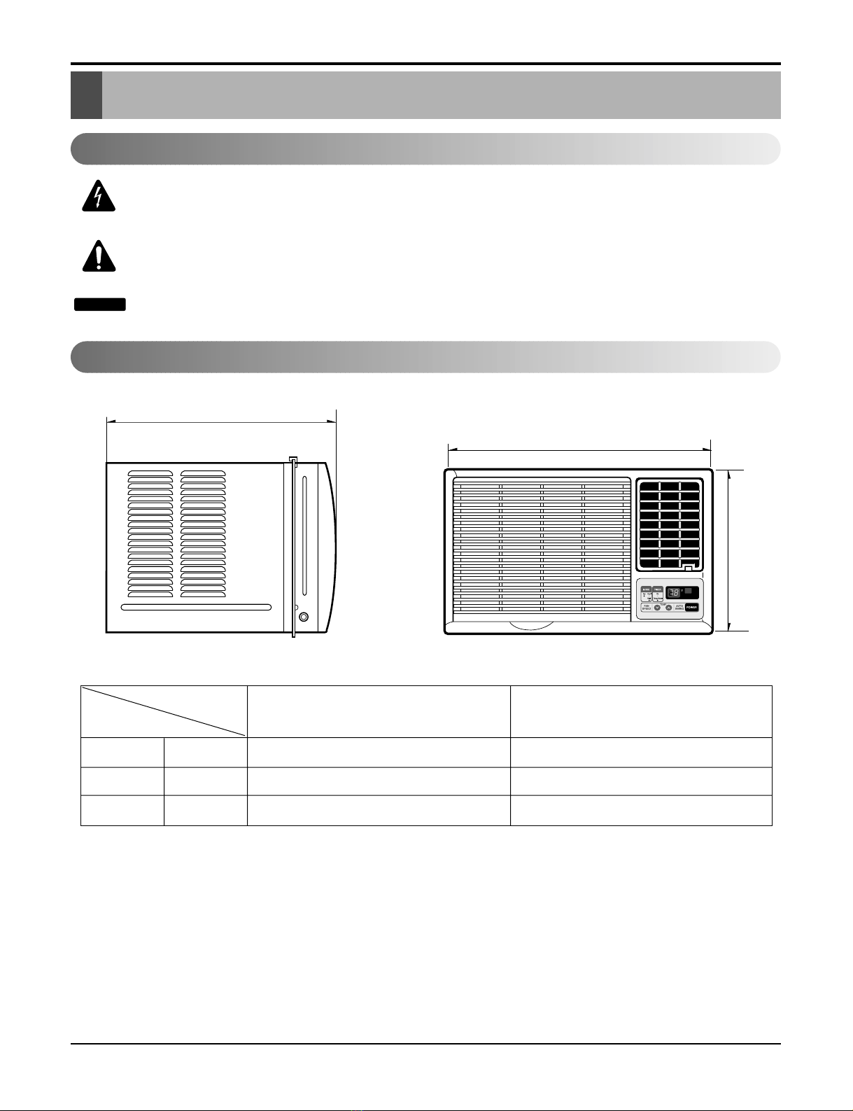
Dimensions......................................................................................................................................................5
Product Specifications...................................................................................................................................6
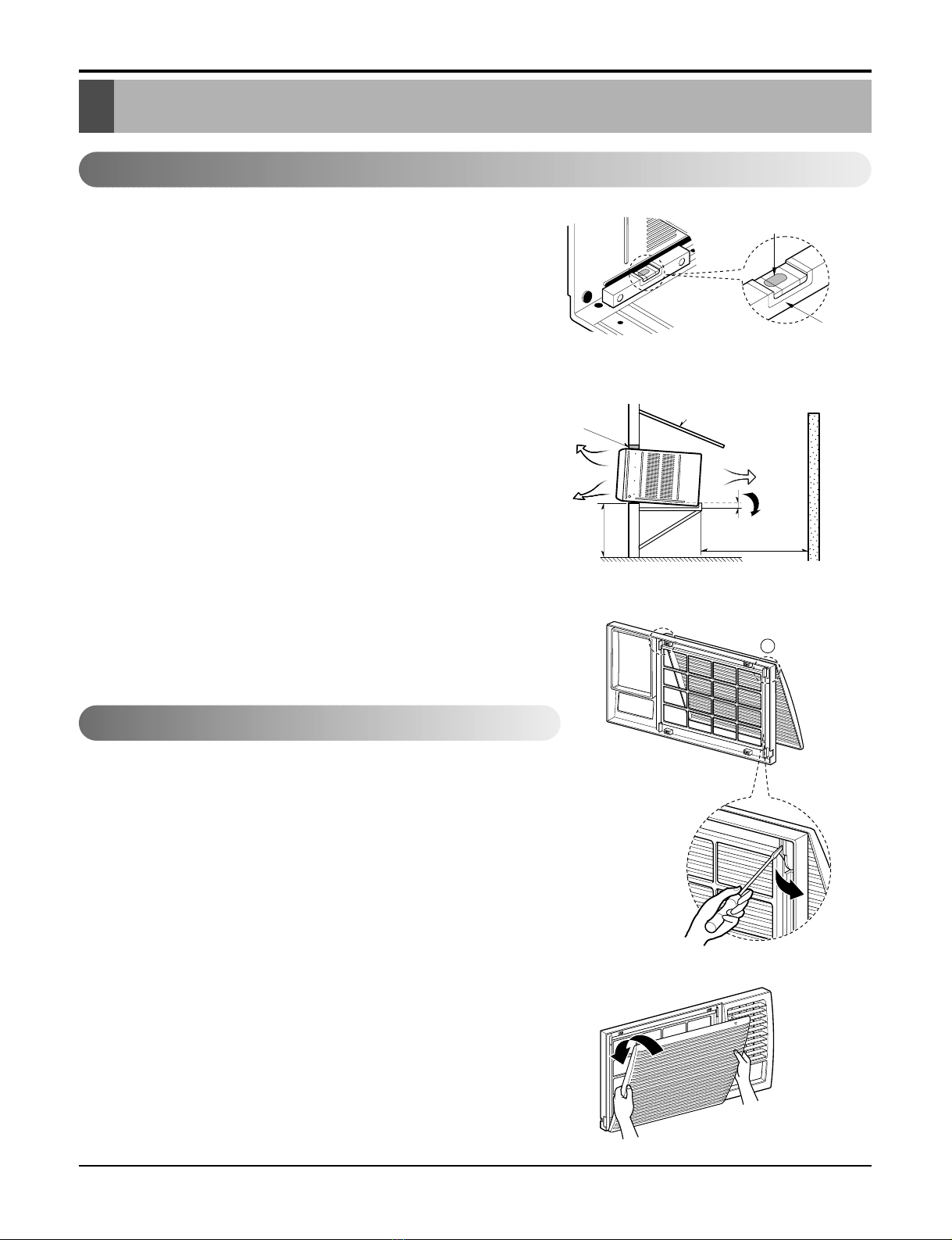
Installation.......................................................................................................................................................8
How to Install the Unit ................................................................................................................................8
How to use the Reversible Inlet grille.........................................................................................................8
Window Requirements...............................................................................................................................9
Installation Kits Contents (some models including installation kit)...........................................................10
Suggested tool Requirements..................................................................................................................10
Cabinet Installation...................................................................................................................................11
Operation.......................................................................................................................................................13
Disassembly instructions.............................................................................................................................14
Mechanical parts......................................................................................................................................14
Air Handling Parts ....................................................................................................................................15
Electrical Parts.........................................................................................................................................16
Refrigeration cycle ...................................................................................................................................19
Schematic Diagram.......................................................................................................................................22
Troubleshooting guide..................................................................................................................................23
Piping System ..........................................................................................................................................23
Troubleshooting guide..............................................................................................................................24
Room Air Conditioner Voltage Limits........................................................................................................26
Exploded View...............................................................................................................................................28
Replacement Parts List ................................................................................................................................29


 null")