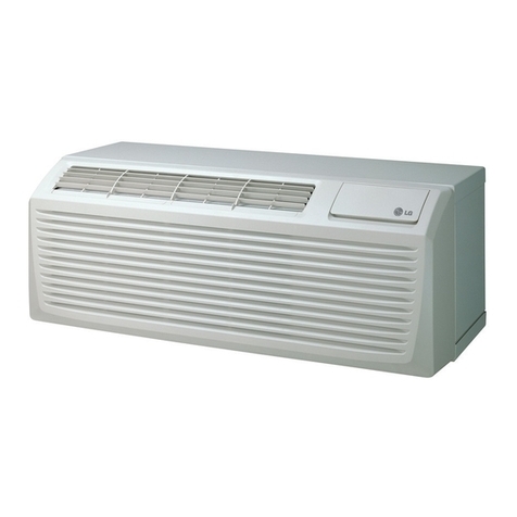
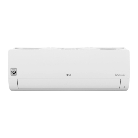
LG ZBNQ09GL1A0 Product guide

Single Free Combination
Cooling only
MFL67986344
Region : Viet Nam
Published on Sep. 21, 2022

Model Line Up
Single Free Combination
General Information

Product Phase Chassis
Capacity
Index Model Name Combination
Indoor Unit
kW
Free Combination
1
U12A 3.5 ZUUQ12GA0 [ZUAA1]
ZBNQ09GL1A0 [ZBNQ09GL1A0]
ZTNQ18GPLE0 [ZTNQ18GPLE0]
ZBNQ12GL2A0 [ZBNQ12GL2A0]
ZTNQ12GULA0 [ZTNQ12GULA0]
U18A 5.3 ZUUQ18GA0 [ZUAB1]
ZBNQ18GL2A0 [ZBNQ18GL2A0]
ZTNQ18GPLA0 [ZTNQ18GPLA0]
ZTNQ24GNLE0 [ZTNQ24GNLE0]
ZBNQ18GM1A0 [ZBNQ18GM1A0]
ZTNQ18GTLA0 [ZTNQ18GTLA0]
U24A 7 ZUUQ24GA0 [ZUAC1]
ZBNQ24GM1A0 [ZBNQ24GM1A0]
ZPNQ24GS1A0 [ZPNQ24GS1A0]
ZTNQ24GTLA0 [ZTNQ24GTLA0]
ZTNQ36GNLE0 [ZTNQ36GNLE0]
ZTNQ30GNLE0 [ZTNQ30GNLE0]
ZTNQ24GPLA0 [ZTNQ24GPLA0]
ZBNQ24GL3A0 [ZBNQ24GL3A0]
ZPNQ36GT3E0 [ZPNQ36GT3E0]
ZPNQ30GR5E0 [ZPNQ30GR5E0]
U36A 10.6
ZUUQ36GA0 [ZUAD1]
ZTNQ36GYLA0 [ZTNQ36GYLA0]
ZBNQ48GM3A0 [ZBNQ48GM3A0]
ZTNQ48GMLA0 [ZTNQ48GMLA0]
ZBNQ36GM3A0 [ZBNQ36GM3A0]
ZTNQ36GNLA0 [ZTNQ36GNLA0]
ZPNQ48GT3A0 [ZPNQ48GT3A0]
ZTNQ48GYLA0 [ZTNQ48GYLA0]
ZPNQ36GR5A0 [ZPNQ36GR5A0]
3 ZUUQ36LA0 [ZUAD3]
ZTNQ36LNLA0 [ZTNQ36LNLA0]
ZPNQ48LT3A0 [ZPNQ48LT3A0]
ZTNQ48LMLA0 [ZTNQ48LMLA0]
ZBNQ36LM3A0 [ZBNQ36LM3A0]
ZBNQ48LM3A0 [ZBNQ48LM3A0]
ZPNQ36LR5A0 [ZPNQ36LR5A0]
* The capacity index may differ from actual capacity values.
Single Free Combination
1. Model Line Up
General Information
1

Single Free Combination
Product Data

1.1 Specifications
Category
Unit Value
Major Minor
Combinational Specification
Power Supply
#1 - 220-230-240, 1, 50/60
#2 - -
Limit Range of Voltage V 187~276
Cooling Capacity
Rated
kW 2.64
Btu/h 9000
Min ~ Max
kW 1.25 ~ 3.19
Btu/h 4260 ~ 10900
Sensible Heat (Rated)
kW 2.218
Btu/h 7560
Heating Capacity
Rated
kW -
Btu/h -
Min ~ Max
kW - ~
Btu/h ~
Low Heating Max (-7℃/19.4℉)
kW -
Btu/h -
Power Input(Cooling) Min ~ Rated ~ Max kW - ~ 0.75 ~
Power Input(Heating) Min ~ Rated ~ Max kW - ~ - ~
Efficiency
EER W/W 3.52
COP W/W -
Running Current(Cooling) Min/Rated/Max A - / 3.41 /
Running Current(Heating) Min/Rated/Max A - / - /
Running Current Maximum A 11
Power Factor(Cooling/Heating) Rated - 0.99 / 0.99
Dehumidification Rate - ℓ/h 0.63
Refrigerant
Type - R32
Additional Charging amount g/m 15
Chargeless-Pipe Length m 15
Connecting Pipe
Liquid mm(inch) Φ6.35 (1/4)
Gas mm(inch) Φ9.52 (3/8)
Piping Length IDU - ODU(Rated / Max / Min) m 7.5 / 30 / 5
Maximum Height Difference IDU - ODU(Max) m 15
Sound Pressure Level(Outdoor Unit) Cooling / Heating (@ 1.5m height) dB(A) 47 / -
Measurement Standard (Pressure Leve
l) - - ISO 3745
Sound Power Level(Outdoor Unit) Cooling / Heating dB(A) -
Measurement Standard (Power Level) - - -
Electrical Characteristic
Minimium Circuit Amperes (MCA) A 9.1
Maximum Fuse Amperes (MFA) A 15
Comp_Rated Load Amperes (Max) A 6.5
Outdoor Fan Motor_Full Load Amperes (FLA /
Max) A 0.25
Outdoor Unit Specification
Classification Chassis - U12A
Power Supply
#1 - 220-230-240, 1, 50/60
#2 - -
Limit Range of Voltage V 187~276
Outdoor Fan
Type - Axial Fan
Air Flow Rate(Max) ㎥/min x No. 28 x 1
Max. External Static Pressure mmAq -
Outdoor Fan Motor Type - BLDC
Single Free Combination
1. ZUUQ12GA0 [ZUAA1] + ZBNQ09GL1A0 [ZBNQ09GL1A0]
Product Data
1-1

Category
Unit Value
Major Minor
Outdoor Fan Motor Drive - External
Output W x No. 43.0 x 1
Compressor
Type - Twin Rotary
Model x No. - DST102MAA x 1
Motor Type - BLDC
Motor Output W x No. 900 x 1
Oil Type - FW68D
Oil Charging amount cc x No. 280 x 1
Heat Exchanger
Rows x Columns x FPI - 2 x 22 x 18
No. - 1
Fin Type - Louver
Corrosion Protection (Coating) - -
Material (Tube / Fin) - -
Face Area ㎡0.31
Dimensions
Net(W x H x D) mm 717 x 483 x 230
Shipping(W x H x D) mm 842 x 530 x 322
Weight
Net kg 24.2
Shipping kg 25.8
Exterior
Color - Warm Gray
RAL (Classic) - RAL 7044
Protection Device
High Pressure Prevention - -
Frost Prevention - -
Discharge Tempreature Control - O
Inverter Protection - O
Refrigerant
Type - R32
Precharged Amount kg 0.75
Control Type - EEV
Drain Pipe(using Drain Pump)
Material - -
O.D / I.D mm(inch) -
Insulation Thickness mm -
Pipe Connecting Socket
Liquid mm(inch) Φ6.35 (1/4)
Gas mm(inch) Φ9.52 (3/8)
Connection Type(Liquid) - Flare
Connection Type(Gas) - Flare
Connecting Cable Power Supply Cable(H07RN-F) mm² × cores 2.5 x 3C
Note
■ Due to our policy of innovation some specifications may be changed without notification.
■ Wiring cable size must comply with the applicable local and national codes. And “Electric characteristics” should be considered for electrical work and design.
Especially the power cable and circuit breaker should be selected in accordance with that.
■ Power factor could vary less than ±1% according to the operating conditions.
■ Sound level values are depend on the ambient conditions and values are normally higher in actual operation.
■ This product contains Fluorinated greenhouse gases.
■ Voltage supplied to the unit terminals should be within the minimum and maximum range.
■ Maximum allowable voltage unbalance between phase is 2%.
■ MSC means the Max. current during the starting of compressor.
■ MSC and RLA are measured as the compressor only test condition.
■ OFM and IFM are measured as the outdoor unit test condition.
■ Select the wire size based on MCA.
■ MFA is used to select the circuit breaker and ground fault circuit interrupter, and all installation site must require attachment of an earth leakage breaker.
[circuit breaker type is ELCB(Earth Leakage Circuit Breaker)].
■ Performances are based on the following conditions :
- Cooling : Indoor Ambient Temp. 27°CDB / 19°CWB, Outdoor Ambient Temp. 35°CDB / 24°CWB
- Heating : Indoor Ambient Temp. 20°CDB / 15°CWB, Outdoor Ambient Temp. 7°CDB / 6°CWB
- Interconnected Pipe Length is standard length and difference of Elevation (Outdoor ~ Indoor Unit) is 0m.
Single Free Combination
1. ZUUQ12GA0 [ZUAA1] + ZBNQ09GL1A0 [ZBNQ09GL1A0]
Product Data
1-2

1.2 List of Functions
Category Functions Value
Reliability
Defrost / Deicing X
High Pressure Switch X
Low Pressure Switch X
Phase Protection X
Restart Delay (3-minutes) O
Self Diagnosis O
Soft Start X
Convenience
Night Low Noise Operation X
Wiring Error Check X
Peak Control X
Mode Lock X
Forced Cooling Operation (Outdoor Unit) X
SLC(Smart Load Control) X
Auto Detecting Mode X
Special Functions ODU Dry Contact Function O (on/off control)
Note
■ O : Applied, X : Not applied
- Accessory : Ordered and purchased separately the accessory package referring to the model name provided and install at field.
- Accessory line-ups varies by region, so check your local catalogue or local sales material.
Single Free Combination
1. ZUUQ12GA0 [ZUAA1] + ZBNQ09GL1A0 [ZBNQ09GL1A0]
Product Data
1-3

1.3 Accessory Compatibility List
Category Accessory Name Model Name Description Value
Central Controller
AC EZ PQCSZ250S0 Small type O
AC EZ touch PACEZA000 Small / Touch type O
AC Smart IV PACS4B000 Touch type O
AC Smart 5 PACS5A000 Touch type O
ACP IV PACP4B000 - O
ACP 5 PACP5A000 - O
AC Manager IV PACM4B000 Integrated O
AC Manager 5 PACM5A000 Integrated O
Gateway
ODU PI485 PMNFP14A1 For 16-room (3 series) O
ACP BACnet PQNFB17C0 - O
ACP Lonwork PLNWKB000 - O
Cloud Gateway PWFMDB200 - X
Integration Device
AHU comm. kit
PAHCMR000 For AHU Control (Multi V / Single ODU Communication) X
PAHCMS000 For AHU Control (Multi V / Single ODU Communication) X
AHU Controller Module
PAHCMC000 For AHU Control (Communication Module) X
PAHCMM000 For AHU Control (Main Module) X
PDI Standard PPWRDB000 Power distributor 2port X
PDI Premium PQNUD1S40 Power distributor 8port X
Note
■ O: Possible, X: Impossible, - : Unconfirmed or irrelevant
■ AC Manager requires ACP or AC Smart.
■ Compatibility of individual controller(wireless/wired remote controller) could be found with function list on Indoor Unit’s PDB.
■ If you need more detail, please refer to the Control(BECON) PDB or the manual of product.
(http://partner.lge.com/global : Home> Doc.Library> Product > Control(BECON)).
■ Accessory line-ups varies by region, so check your local catalogue or local sales material.
Single Free Combination
1. ZUUQ12GA0 [ZUAA1] + ZBNQ09GL1A0 [ZBNQ09GL1A0]
Product Data
1-4

1.4 Dimensions
1.4.1 Product
Chassis code : U12A
DWG No. : TBW35989601_Rev01
Single Free Combination
1. ZUUQ12GA0 [ZUAA1] + ZBNQ09GL1A0 [ZBNQ09GL1A0]
Product Data
1-5

1.4.2 Install Space
Obstacle on the Suction side
Obstacle on the Suction and Discharge side
Collective/Continuous Installation
(Multiple Columns)
Front
Rt
Re
Lt
Front Front
RtBw
Re
Lt
Front
Ft
Re
Front Front
Bw
Re
FrontFront Front
Ft ReFbRb
FrontFront Front
Ft ReFbRb
Bw
Front
Ft
Front Front
Bw
Ft
Front
Ft
Front
Re
Case 1
※Case 1 : No obstacle on top side
Case 2 : Obstacle on top side
※For Rear Piping / External SVC Valve type / Side-CBOX type
: Re,Lt
≥
300(11-13/16) and Rt,Bw,Rb
≥
600(23-5/8) for ALL CASE.
※ In case of series installation (2 Units or more)
for 2 Fan models, Ld should be lower than H/2.
For Side Discharge (capacity <28.0 kW)
Case 2
Re ≥ 100(3-15/16)To ≥ 1,000(39-3/8)
Tf ≤ 500(19-11/16)
To ≥ 1,000(39-3/8)
Tr ≤ 500(19-11/16)
To ≥ 1,000(39-3/8)
Tf ≤ 500(19-11/16)
To ≥ 1,000(39-3/8)
Tf ≤ 500(19-11/16)
Re ≥ 300(11-13/16)
Case 1 Case 2
Re ≥ 100(3-15/16)
Lt ≥ 100(3-15/16)
Rt ≥ 100(3-15/16)
Re ≥ 300(11-13/16)
Lt ≥ 150(5-29/32)
Rt ≥ 150(5-29/32)
Case 1 Case 2
Re ≥ 300(11-13/16)
Lt ≥ 1,000(39-3/8)
Rt ≥ 200(7-7/8)
Bw ≥ 100(3-15/16)
Re ≥ 300(11-13/16)
Lt ≥ 1,000(39-3/8)
Rt ≥ 200(7-7/8)
Bw ≥ 100(3-15/16)
Case 1 Case 2
Ft ≥ 500(19-11/16) Ft ≥ 500(19-11/16)
Case 1 Case 2
Ft ≥ 1,000(39-3/8)
Bw ≥ 100(3-15/16)
Ft ≥ 1,000(39-3/8)
Bw ≥ 100(3-15/16)
Case 1 Case 2
Ft ≥ 500(19-11/16)
Re ≥ 300(11-13/16)
Ft ≥ 1,000(39-3/8)
Rb ≥ 200(7-7/8)
Fb ≥ 2,000(78-3/4)
Re ≥ 100(3-15/16)
※In case of Multiple columns/continuous installation,
Ls should be lower than H.
Ft ≥ 1,500(59-1/16)
Rb ≥ 600(23-5/8)
Fb ≥ 3,000(118-1/8)
Re ≥ 300(11-13/16)
Bw ≥ 100(3-15/16)
Ft ≥ 1,000(39-3/8) *
Re ≥ 300(11-13/16)
* If Ls ≤ H/2,
Ft ≥ 750(29-17/32)
Case 1 Case 2
Ft ≥ 1,000(39-3/8)
Re ≥ 300(11-13/16)
Bw ≥ 100(3-15/16)
Ft ≥ 1,250(49-7/32)
Re ≥ 300(11-13/16)
Bw ≥ 100(3-15/16)
Case 1 Case 2
Ft ≥ 500(19-11/16)
Re ≥ 300(11-13/16)
Ft ≥ 1,000(39-3/8)
Re ≥ 300(11-13/16)
Case 1
1 Column
Case 2
Ft ≥ 1,500(59-1/16)
Re ≥ 300(11-13/16)
Bw ≥ 100(3-15/16)
Ft ≥ 1,500(59-1/16)
Re ≥ 300(11-13/16)
Bw ≥ 100(3-15/16)
[Unit : mm(inch)]
Front
H
Ld
Ls
Ft
Re
Ld >H (Ls should be lower H.)
※Close the bottom of the installation frame
to prevent the discharged
air from being bypassed
Front
Ft
Re
H
Ld
Ls
Ld ≤ H
Front Front Front
Ft Fb
Rb Re
Ls
H
Front Tr
To
Ft
Front
Tf
To
Re
Front Tr
To
Ft
Re
Front
Tf
To
Ft
Re
Obstacle on the Discharge side
Multiple Columns
Note
■ If there is a concern about product performance degradation due to group installation or interference with obstacles, secure an additional separation distance.
■ Secure enough space for smooth service and maintenance.
■ According to product type, model line up, sales region..etc, applicability of each chassis could be different.
Single Free Combination
1. ZUUQ12GA0 [ZUAA1] + ZBNQ09GL1A0 [ZBNQ09GL1A0]
Product Data
1-6

1.5 Piping Diagrams
Refrigerant Flow
M
Discharge
Temperature
Thermistor
Compressor
Inverter
Electronic
Expansion Strainer
Valve
Inlet Air
Temperature
Thermistor
Outdoor Unit
Flare Connection
Flare Connection
Temperature
Thermistor
Condensing
Accumulator
Single Free Combination
1. ZUUQ12GA0 [ZUAA1] + ZBNQ09GL1A0 [ZBNQ09GL1A0]
Product Data
1-7

1.6 Wiring Diagrams
MEZ65919708 Rev.01_052722
Optional or Factory installed*
Field Wiring
Factory Wiring
•
This function can be optional or factory installed depending on the application model.
You need to buy a dedicated circuit separately.
*
INFORMATION
BK
BR
BL
RD
WH
YL
GN/YL
EEV
: BLACK
MOTOR
: BLUE
: BROWN
: RED
: WHITE
: YELLOW
: GREEN/YELLOW
: ELECTRONIC EXPANSION VALVE
: FAN MOTOR
CN_UVW
250 V / T3.15 A
250 V / T3.15 A
CN_FAN
CN_EEV
CN_TH1CN_TH2
CN2 CN3
CN_COIL1
CN_COIL2
WCN_L
WCN_N
250 V / T20 A
COM_RD
250 V / T5 A
CN_CENTRAL
CN_CP_L CN_CP_N
Single Free Combination
1. ZUUQ12GA0 [ZUAA1] + ZBNQ09GL1A0 [ZBNQ09GL1A0]
Product Data
1-8

1.7 Capacity Tables
1.7.1 Cooling
Outdoor
Air Temp.
(°C,DB)
Indoor Air Temp. (°C, DB/WB)
20.0 / 14.0 22.0 / 16.0 25.0 / 18.0 27.0 / 19.0 28.0 / 20.0 30.0 / 22.0 32.0 / 24.0
TC SHC PI TC SHC PI TC SHC PI TC SHC PI TC SHC PI TC SHC PI TC SHC PI
20 1.55 1.49 0.31 2.02 1.78 0.38 2.37 2.07 0.44 2.64 2.22 0.49 2.73 2.21 0.49 2.91 2.18 0.50 3.11 2.15 0.50
25 1.55 1.49 0.36 2.02 1.78 0.45 2.37 2.07 0.52 2.64 2.22 0.57 2.73 2.21 0.58 2.91 2.18 0.59 3.11 2.15 0.60
32 1.55 1.49 0.44 2.02 1.78 0.55 2.37 2.07 0.64 2.64 2.22 0.70 2.73 2.21 0.71 2.91 2.18 0.72 3.11 2.15 0.72
35 1.55 1.49 0.47 2.02 1.78 0.59 2.37 2.07 0.68 2.64 2.22 0.75 2.73 2.21 0.76 2.91 2.18 0.77 3.11 2.15 0.78
40 1.55 1.49 0.50 2.02 1.78 0.63 2.37 2.07 0.72 2.64 2.22 0.79 2.73 2.21 0.80 2.91 2.18 0.82 3.11 2.15 0.82
43 1.55 1.49 0.51 2.02 1.78 0.65 2.37 2.07 0.75 2.64 2.22 0.82 2.73 2.21 0.83 2.91 2.18 0.85 3.11 2.15 0.85
46 1.55 1.49 0.53 2.02 1.78 0.67 2.37 2.07 0.77 2.64 2.22 0.85 2.73 2.21 0.86 2.91 2.18 0.87 3.11 2.15 0.88
48 1.55 1.49 0.55 2.02 1.78 0.69 2.37 2.07 0.80 2.53 2.15 0.82 2.60 2.12 0.83 2.75 2.07 0.84 2.91 2.02 0.85
50 1.55 1.49 0.57 2.02 1.78 0.71 2.37 2.07 0.77 2.43 2.07 0.79 2.48 2.03 0.80 2.59 1.96 0.81 2.71 1.89 0.82
Note
■ DB : Dry bulb temperature(℃), WB : Wet bulb temperature(℃)
■ TC : Total Capacity(kW), SHC : Sensible Heat Capacity(kW)
■ PI : Power Input (kW, Compressor + indoor fan motor + outdoor fan motor)
■ All capacities are net. A deduction of capacity due to operating heat of indoor unit motor is reflected.
■ Direct interpolation is permissible. Do not extrapolate.
■ Rated capacities and power inputs are based on standard temperature and piping conditions, and it can be found on specifications table.
Except for rated value, the performance is not guaranteed.
■ In accordance with the test standard(or nations), the rating will vary slightly.
Single Free Combination
1. ZUUQ12GA0 [ZUAA1] + ZBNQ09GL1A0 [ZBNQ09GL1A0]
Product Data
1-9

1.8 Capacity Correction Factor
Operation
Capacity correction factor (%) by Equivalent pipe length (m)
5 7.5 10 15 20 25 30 35 40 45 50
Cooling 100.0 100.0 99.6 98.8 98.0 97.2 96.4 - - - -
Note
In Order to estimate the actual system capacity, the influence of various installation conditions should be reflected.
Reflect the capacity correction factor effect of piping installation as below.
■ Qodu [from specification table] : Outdoor unit standard capacity.
■ Q(Ti, To) [from capacity table] : Outdoor unit capacity at Ti, To temperature.
■ F(Ti, To) = Q(Ti, To) / Qodu. : Outdoor unit capacity correction factor
■ Fpiping for piping length [from capacity correction factor table] : Piping correction factor
■ Indoor unit actual capacity : Qactual = Qodu x F(Ti, To) x Fpiping
Single Free Combination
1. ZUUQ12GA0 [ZUAA1] + ZBNQ09GL1A0 [ZBNQ09GL1A0]
Product Data
1-10

1.9 Operation Limits
1.9.1 Cooling
Indoor Temperature [°C WB]
Outdoor Temperature [°C DB]
-20
50
45
40
35
30
25
20
15
48
10
5
0
-5
-10
-15
-20
10 12 2315 20 25 28
Continuous
operation
Operative
operation
Note
■ Warming up operation and operative mean that the outdoor unit operates to reach the range of continuous operating, however it may not operate continuously
due to safety or protection logic.
Single Free Combination
1. ZUUQ12GA0 [ZUAA1] + ZBNQ09GL1A0 [ZBNQ09GL1A0]
Product Data
1-11

1.10 Sound Levels
1.10.1 Pressure Levels
63 1252505001000200040008000
45.1 48.2
Overall [dB(A)]
46.8 44.0 41.1 39.2 33.8 34.4 47.0
Octave Band [Hz]
Cooling [dB]
10
15
20
25
30
35
40
45
50
55
60
65
70
75
80
63 125 250 500 1000 2000 4000 8000
Octave Band Sound Pressure Level (0dB = 20μPa )
Octave Band Center Frequency (Hz)
NC-15
NC-20
NC-25
NC-30
NC-35
NC-40
NC-45
NC-50
NC-55
NC-60
NC-65
Approximate
Hearing
Threshold
■Cooling
Sound level [ dB(A), @ Standard condition ]
Cooling / Heating (@ 1.5m height) 47 / -
Note
■ Data is valid at diffuse field condition.
■ Data is valid at nominal operating condition.
■ Reference accoustic pressure 0dB = 20μPa.
■ Refer to the model specifications for nominal conditions. (Power source and Ambient temperature, etc)
■ Sound levels can be increased in accordance with installation and operating conditions.
(Operating conditions include some functional condition like Static pressure mode, air guide use, Room target temperature setting, etc and these
functions are different in accordance with each model.)
■ Sound level will vary depending on a range of factors such as the construction(acoustic absorption coefficient) of particular room in which the
equipment in installed.
■ Sound pressure level is measured on the rated condition in the anechoic rooms by ISO 3745 standard.
Therefore, these values can be increased owing to ambient conditions during operation.
Single Free Combination
1. ZUUQ12GA0 [ZUAA1] + ZBNQ09GL1A0 [ZBNQ09GL1A0]
Product Data
1-12

2.1 Specifications
Category
Unit Value
Major Minor
Combinational Specification
Power Supply
#1 - 220-230-240, 1, 50/60
#2 - -
Limit Range of Voltage V 187~276
Cooling Capacity
Rated
kW 5.13
Btu/h 17500
Min ~ Max
kW 1.58 ~ 5.42
Btu/h 5400 ~ 18500
Sensible Heat (Rated)
kW 4.72
Btu/h 16100
Heating Capacity
Rated
kW -
Btu/h -
Min ~ Max
kW - ~
Btu/h ~
Low Heating Max (-7℃/19.4℉)
kW -
Btu/h -
Power Input(Cooling) Min ~ Rated ~ Max kW - ~ 1.75 ~
Power Input(Heating) Min ~ Rated ~ Max kW - ~ - ~
Efficiency
EER W/W 2.93
COP W/W -
Running Current(Cooling) Min/Rated/Max A - / 7.95 /
Running Current(Heating) Min/Rated/Max A - / - /
Running Current Maximum A 11
Power Factor(Cooling/Heating) Rated - 0.99 / 0.99
Dehumidification Rate - ℓ/h 1.0
Refrigerant
Type - R32
Additional Charging amount g/m 15
Chargeless-Pipe Length m 15
Connecting Pipe
Liquid mm(inch) Φ6.35 (1/4)
Gas mm(inch) Φ12.7 (1/2)
Piping Length IDU - ODU(Rated / Max / Min) m 7.5 / 30 / 5
Maximum Height Difference IDU - ODU(Max) m 15
Sound Pressure Level(Outdoor Unit) Cooling / Heating (@ 1.5m height) dB(A) 47 / -
Measurement Standard (Pressure Leve
l) - - ISO 3745
Sound Power Level(Outdoor Unit) Cooling / Heating dB(A) -
Measurement Standard (Power Level) - - -
Electrical Characteristic
Minimium Circuit Amperes (MCA) A 9.0
Maximum Fuse Amperes (MFA) A 15
Comp_Rated Load Amperes (Max) A 6.5
Outdoor Fan Motor_Full Load Amperes (FLA /
Max) A 0.25
Outdoor Unit Specification
Classification Chassis - U12A
Power Supply
#1 - 220-230-240, 1, 50/60
#2 - -
Limit Range of Voltage V 187~276
Outdoor Fan
Type - Axial Fan
Air Flow Rate(Max) ㎥/min x No. 28 x 1
Max. External Static Pressure mmAq -
Outdoor Fan Motor Type - BLDC
Single Free Combination
2. ZUUQ12GA0 [ZUAA1] + ZTNQ18GPLE0 [ZTNQ18GPLE0]
Product Data
2-1

Category
Unit Value
Major Minor
Outdoor Fan Motor Drive - External
Output W x No. 43.0 x 1
Compressor
Type - Twin Rotary
Model x No. - DST102MAA x 1
Motor Type - BLDC
Motor Output W x No. 900 x 1
Oil Type - FW68D
Oil Charging amount cc x No. 280 x 1
Heat Exchanger
Rows x Columns x FPI - 2 x 22 x 18
No. - 1
Fin Type - Louver
Corrosion Protection (Coating) - -
Material (Tube / Fin) - -
Face Area ㎡0.31
Dimensions
Net(W x H x D) mm 717 x 483 x 230
Shipping(W x H x D) mm 842 x 530 x 322
Weight
Net kg 24.2
Shipping kg 25.8
Exterior
Color - Warm Gray
RAL (Classic) - RAL 7044
Protection Device
High Pressure Prevention - -
Frost Prevention - -
Discharge Tempreature Control - O
Inverter Protection - O
Refrigerant
Type - R32
Precharged Amount kg 0.75
Control Type - EEV
Drain Pipe(using Drain Pump)
Material - -
O.D / I.D mm(inch) -
Insulation Thickness mm -
Pipe Connecting Socket
Liquid mm(inch) Φ6.35 (1/4)
Gas mm(inch) Φ9.52 (3/8)
Connection Type(Liquid) - Flare
Connection Type(Gas) - Flare
Connecting Cable Power Supply Cable(H07RN-F) mm² × cores 2.5 x 3C
Note
■ Due to our policy of innovation some specifications may be changed without notification.
■ Wiring cable size must comply with the applicable local and national codes. And “Electric characteristics” should be considered for electrical work and design.
Especially the power cable and circuit breaker should be selected in accordance with that.
■ Power factor could vary less than ±1% according to the operating conditions.
■ Sound level values are depend on the ambient conditions and values are normally higher in actual operation.
■ This product contains Fluorinated greenhouse gases.
■ Voltage supplied to the unit terminals should be within the minimum and maximum range.
■ Maximum allowable voltage unbalance between phase is 2%.
■ MSC means the Max. current during the starting of compressor.
■ MSC and RLA are measured as the compressor only test condition.
■ OFM and IFM are measured as the outdoor unit test condition.
■ Select the wire size based on MCA.
■ MFA is used to select the circuit breaker and ground fault circuit interrupter, and all installation site must require attachment of an earth leakage breaker.
[circuit breaker type is ELCB(Earth Leakage Circuit Breaker)].
■ Performances are based on the following conditions :
- Cooling : Indoor Ambient Temp. 27°CDB / 19°CWB, Outdoor Ambient Temp. 35°CDB / 24°CWB
- Heating : Indoor Ambient Temp. 20°CDB / 15°CWB, Outdoor Ambient Temp. 7°CDB / 6°CWB
- Interconnected Pipe Length is standard length and difference of Elevation (Outdoor ~ Indoor Unit) is 0m.
Single Free Combination
2. ZUUQ12GA0 [ZUAA1] + ZTNQ18GPLE0 [ZTNQ18GPLE0]
Product Data
2-2

2.2 List of Functions
Category Functions Value
Reliability
Defrost / Deicing X
High Pressure Switch X
Low Pressure Switch X
Phase Protection X
Restart Delay (3-minutes) O
Self Diagnosis O
Soft Start X
Convenience
Night Low Noise Operation X
Wiring Error Check X
Peak Control X
Mode Lock X
Forced Cooling Operation (Outdoor Unit) X
SLC(Smart Load Control) X
Auto Detecting Mode X
Special Functions ODU Dry Contact Function O (on/off control)
Note
■ O : Applied, X : Not applied
- Accessory : Ordered and purchased separately the accessory package referring to the model name provided and install at field.
- Accessory line-ups varies by region, so check your local catalogue or local sales material.
Single Free Combination
2. ZUUQ12GA0 [ZUAA1] + ZTNQ18GPLE0 [ZTNQ18GPLE0]
Product Data
2-3

2.3 Accessory Compatibility List
Category Accessory Name Model Name Description Value
Central Controller
AC EZ PQCSZ250S0 Small type O
AC EZ touch PACEZA000 Small / Touch type O
AC Smart IV PACS4B000 Touch type O
AC Smart 5 PACS5A000 Touch type O
ACP IV PACP4B000 - O
ACP 5 PACP5A000 - O
AC Manager IV PACM4B000 Integrated O
AC Manager 5 PACM5A000 Integrated O
Gateway
ODU PI485 PMNFP14A1 For 16-room (3 series) O
ACP BACnet PQNFB17C0 - O
ACP Lonwork PLNWKB000 - O
Cloud Gateway PWFMDB200 - X
Integration Device
AHU comm. kit
PAHCMR000 For AHU Control (Multi V / Single ODU Communication) X
PAHCMS000 For AHU Control (Multi V / Single ODU Communication) X
AHU Controller Module
PAHCMC000 For AHU Control (Communication Module) X
PAHCMM000 For AHU Control (Main Module) X
PDI Standard PPWRDB000 Power distributor 2port X
PDI Premium PQNUD1S40 Power distributor 8port X
Note
■ O: Possible, X: Impossible, - : Unconfirmed or irrelevant
■ AC Manager requires ACP or AC Smart.
■ Compatibility of individual controller(wireless/wired remote controller) could be found with function list on Indoor Unit’s PDB.
■ If you need more detail, please refer to the Control(BECON) PDB or the manual of product.
(http://partner.lge.com/global : Home> Doc.Library> Product > Control(BECON)).
■ Accessory line-ups varies by region, so check your local catalogue or local sales material.
Single Free Combination
2. ZUUQ12GA0 [ZUAA1] + ZTNQ18GPLE0 [ZTNQ18GPLE0]
Product Data
2-4
This manual suits for next models
31
Table of contents
Other LG Air Conditioner manuals
Popular Air Conditioner manuals by other brands

Daikin
Daikin EWLD120MBYNN Installation instruction

Honeywell
Honeywell CL48PM user manual

Whynter
Whynter MSFS-024H23016-01NE instruction manual

Tokyo Gas
Tokyo Gas MISTY IBD-4110ACSKJ3M manual

Dometic
Dometic Blizzard NXT H540315 installation instructions

Panasonic
Panasonic S-20LM3HPQ Installation and operation manual