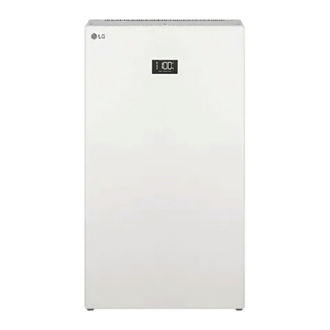
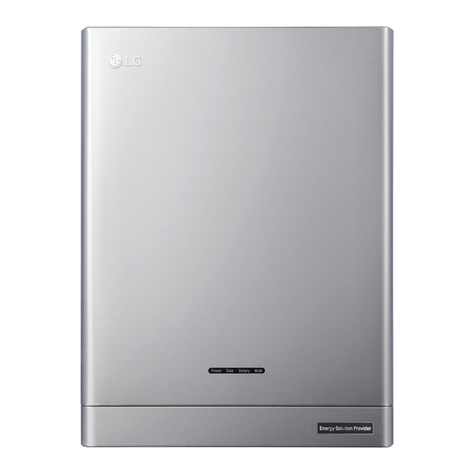
LG RESU FLEX User manual

Full Installation Manual for RESU FLEX
LG Energy Solution strongly advises users to exercise due care in following LG Energy
Solution’s product installation manual. Warranty claims are invalid if damage is caused
by human error in a manner inconsistent with the installation manual’s instructions.
Version 1.0

2
About this manual
This manual describes how to install LG Energy Solution’s RESU FLEX battery
pack. Read this manual before you attempt to install the product, and follow the
instructions throughout the installation process. If you are uncertain about any
of the requirements, recommendations, or safety procedures described in this
manual, contact LG Energy Solution immediately for advice and clarication.
The information included in this manual is accurate at the time of publication.
However, the product specications are subject to change without prior notice.
In addition, the illustrations in this manual are meant to help explain system
conguration concepts and installation instructions. The illustrated items may
differ from the actual items at the installation location.
1. Safety ············································································································· 5
1.1 Symbols ·······················································································································5
1.2 Safety Instructions ··································································································5
1.2.1 General Safety Precautions ········································································5
1.2.2 Battery Handling Guide ············································································· 6
1.2.3 Response to Emergency Situations ······················································ 8
1.3 Warning Label ········································································································· 9
1.3.1 BPU ····················································································································· 9
1.3.2 BMA ··················································································································10
2. Product Introduction ················································································· 11
2.1 Technical Data ········································································································· 11
2.1.1 Dimensions and Weight ·············································································· 11
2.1.2 Performance ·································································································· 12
2.1.3 Arc Flash Protection Calculations ························································ 13
2.2 Features ··················································································································· 15
2.3 Maintenance ··········································································································· 15
2.4 Packaging Specications ·················································································· 15
Contents

ENGLISH
3
3. Installation ································································································· 16
3.1 Package Contents ·································································································16
3.1.1 BPU Package ································································································16
3.1.2 BPU Bundle Package ················································································16
3.1.3 BMA Package ································································································ 17
3.1.4 Option Item Package (Optional Standing type) ····························· 17
3.1.5 Option Item Package (Wall Mounting type) ···································· 18
3.2 Installation Location ···························································································· 18
3.3 Lifting Guide ··········································································································19
3.3.1 Only BMA ·······································································································19
3.3.2 BMA With Basic Standing Bracket ······················································19
3.3.3 BMA With Optional Standing Bracket ··············································20
3.3.4 BMA With Pack Mounting Bracket ·····················································20
3.4 Tools ························································································································ 21
3.5 Safety Gear ············································································································ 22
3.6 Standing Installation (Basic Standing / Optional Standing) ·····················22
3.6.1 Items for Stand type (Basic Standing / Optional Standing) ····· 22
3.6.2 Clearance ······································································································ 22
3.6.3 Install Battery Pack for Stand type ··················································· 23
3.6.4 Finalizing Installation ···············································································29
3.7 Wall-mounting Installation ··············································································· 31
3.7.1 Items for Wall Mount Type ····································································· 32
3.7.2 Clearance ······································································································ 32
3.7.3 Mounting Brackets Installation ···························································· 32
3.7.4
Installation and Cable Connection of BMA and BPU for Wall type
··34
3.7.5 Finalizing Installation ·············································································· 40
4. Connection to the Inverter ······································································ 42
4.1 Prepare for connection ······················································································42
4.2 Communication Line Connection ·································································43
4.3 Power (Charging/Discharging) Line Connection ···································45
4.4 End of Connection ·····························································································46

4
5 Commissioning ··························································································· 48
5.1 Pre-preparation ····································································································48
5.1.1 Account ···········································································································48
5.1.2 App ··················································································································48
5.2 Battery Setting . ····················································································································49
5.3 LED Indicator ········································································································49
5.3.1 LED State for Battery Setting ·······························································50
5.3.2 LED state for operation ··········································································50
5.3.3 Powering On the Battery Pack ····························································· 51
5.3.4 Shutting Off the Battery Pack ······························································· 51
6. Troubleshooting ························································································ 52
6.1 Troubleshooting Overview ··············································································· 52
6.1.1 Post-Installation Checklist ······································································· 53
6.12 Troubleshooting Guidelines ····································································54
6.1.3 Contact Information ··················································································56

ENGLISH
5
1. Safety
1.1 Symbols
Caution, risk of electric shock
Do not place or install near ammable or explosive materials
Install the product out of reach of children
Read the instruction manual, in its entirety, before starting installation and
operation
Heavy weight may cause serious back injuries
Do not dispose of the product with household waste
Recyclable
Disconnect the equipment before carrying out maintenance or repair
Observe precautions for handling electrostatic-sensitive devices
Protective Class 1
Caution, risk of electric shock, energy storage timed discharge.
1.2 Safety Instructions
For safety reasons, installers are responsible for familiarizing themselves
with the contents of this document and all warnings before performing
installation and service.
1.2.1 General Safety Precautions
Over-voltages or wrong wiring can damage the battery pack and cause
combustion, which can be extremely dangerous.
Any type of product breakdown may lead to a leakage of electrolytes or
ammable gas.
Avoid installing the battery pack where ammable materials are stored. Do
not install in places where explosive gas or chemicals are present.
During installation of the battery, the utility grid and solar input must be

6
disconnected from the Battery Pack wiring. Wiring must be carried out by
qualied personnel.
Battery pack should only be serviced by qualied personnel.
The electronics inside the battery pack are vulnerable to electrostatic
discharge.
Be sure to be grounded before handling the battery pack.
Read the label with Warning Symbols and Precautions, which are visible
under the Battery Cover (see Section 1.3 Warning Label).
1.2.2 Battery Handling Guide
• Do not expose the battery to an open ame.
• Do not place the product near to highly ammable materials.
• Do not expose or place near water sources such as downspouts or
sprinklers.
• Do not store or install the product in direct sunlight.
• Do not install the product in an airtight enclosure or in an area without
ventilation.
• Do not install the product in living area of dwelling units or in sleeping
units other than within utility closets and storage or utility spaces.
• Store in a cool and dry place. (Do not store in greenhouses or storage
areas for hay, straw, chaff, animal feed, fertilizer, vegetables, or fruit
products.)
• Store the product on a at, level surface.
• Store the product out of reach of children and animals.
• Store the product in clean environment, free of dust, dirt and debris.
• Do not disconnect, disassemble or repair the product unqualied
personnel. Only qualied personal are to handle, install and service the
Product.
• Do not damage the Product by dropping, deforming, impacting, cutting
or penetrating with a sharp object. Doing so may cause a re or leakage
of electrolytes.

ENGLISH
7
• Do not touch the product if liquid spills on it. There is a risk of electric
shock. Handle the battery wearing insulated gloves.
• Do not step on the product or the product՚s packaging since the
product may be damaged.
• Do not place any foreign objects on top of the Battery Pack and on the
cooling n.
• Do not put the battery pack upside down on the ground.
• Do not connect the power cables at terminal the block in the opposite
direction.
• Do not charge or discharge a damaged battery.
• If the Product is installed in a garage or carport, ensure there is
adequate clearance from vehicles.
• The battery pack has been certied IP55 and can be installed indoors
as well as outdoors. However, if installed outdoors, do not allow the
battery pack to be exposed to direct sunlight or water sources, as they
may cause:
- Power limitation phenomena in the battery (with a resulting decrease
in energy production by the system).
- Premature wear of the electrical/electromechanical and mechanical
components.
- Reduction in performance, performance warranty and possible
damage of the battery
• Only use the product with a LGES-authorized inverter.
For a list of compatible inverters, go to :
https://www.lgessbattery.com/us (in case of North America)
https://www.lgessbattery.com/au (in case of Australia)
https://www.lgessbattery.com/eu (in case of all EU-countries in general)
https://www.lgessbattery.com/de (in case of Germany)
https://www.lgessbattery.com/it (in case of Italy)
https://www.lgessbattery.com/es (in case of Spain)
• Do not connect any AC conductors or photovoltaic conductors directly
to the battery pack. These are only to be connected to the inverter.

8
1.2.3 Response to Emergency Situations
The Product includes internal fault mechanisms designed to prevent
failures and subsequent risk hazards. However, LG ES cannot guarantee
safety performance of the Product is ever exposed to abuse, damage or
negligence.
• If a user happens to be exposed to the internal materials of the battery
cell due to damage on the outer casing, the following actions are
recommended.
In case of inhalation: Leave the contaminated area immediately and
seek medical attention.
In case of contact with eyes: Rinse eyes with running water for 15
minutes and seek medical attention.
In case of contact with skin: Wash the contacted area with soap
thoroughly and seek medical attention.
In case of ingestion: Induce vomiting and seek medical attention.
If a re breaks out at the location where the battery pack is installed,
perform the following countermeasures.
• Utilize re-extinguishing media
A respirator is not required during normal operation.
Use an FM-200 or CO2 extinguisher for battery res.
Use an ABC re extinguisher if the re is not from the battery and has
not yet spread to it.
• Follow proper re-ghting instructions
1) If a re occurs when charging batteries, provided it is safe to do so,
disconnect the battery pack circuit breaker to shut off the power
charge.
2) If the battery pack is not on re yet, extinguish the re before the
battery pack catches re preferably with water.
3) If the battery pack is on re, do not try to extinguish it, and evacuate
people from the premises immediately.

ENGLISH
9
1.3 Warning Label
Product/warning label and Battery Control Unit’s traceable label are
behind the front cover. The Design cover opens. Battery Modules’
traceable labels are attached to the side of the Battery Modules.
1.3.1 BPU
1. Product/Warning label 2. Traceable label

10
1.3.2 BMA
1. Warning label
4.3 kWh
RESU FLEX
EH117037P9S1
48.0kg(105.8lb)
117.44V
INP5/101/150[5P32S]E/-10+50/95
37.0 Ah
2. BMA label
①
②
①
PJT Name Criteria
EH117037P9S1 B
Country of production
Line
M A
②
Year Month Day
21 07 16
Production number
3 digits (0001 – 9999)

ENGLISH
11
2. Product Introduction
2.1 Technical Data
2.1.1 Dimensions and Weight
665.2mm
665.2mm
148.4mm
665.2mm
665.2mm
148.4mm
P/N EH117037P9S1 (BMA)
Width 665.2 mm
Height 665.2 mm
Depth 148.4 mm
Weight 48.9 kg
665.2mm
665.2mm
148.4mm
665.2mm
665.2mm
148.4mm
P/N EEA00462AA (BPU)
Width 665.2 mm
Height 665.2 mm
Depth 148.4 mm
Weight 16.5 kg
* Without Design Cover and Brackets
** Weight of BPU(with Design Cover) : 16.6 kg

12
2.1.2 Performance
Model Name RESU FLEX
8.6
RESU FLEX
12.9
RESU FLEX
17.2
Electrical Characteristics
Conguration BPU 1ea, BMA
2ea
BPU 1ea, BMA
3ea
BPU 1ea, BMA
4ea
Usable Energy
1)
8.6 kWh 12.9 kWh 17.2 kWh
Battery Capacity 37Ah 37Ah 37Ah
Voltage Range 192 to 265.6V 288 to 398.4V 384 to 531.2V
Max. Current 22A 22A 22A
Max. Power 4.3kWh 6.5kWh 8.5kWh
Peak Power
2)
(only discharging) 5kW for 3sec 7kW for 3sec 11kW for 3sec
Short circuit Current
Communication Interface RS485, RJ45
DC Disconnect Circuit Breaker
Connection Method Spring Type Connector
User Interface LEDs for Normal and Fault Operation
Operating conditions
Installation Location Indoor/Outdoor
Ingress Rating IP55
Operating Temperature
(Recommended) 14°F to 122°F (-10°C to 50°C)
Operating Temperature 68°F to 86°F (20°C to 30°C)
Storage Temperature
-22°F to 140°F (-30°C to 60°C), acceptable for 7
-4°F to 113°F (-20°C to 45°C), acceptable for the
rst 6 months
-4°F to 86°F (-20°C to 30°C), acceptable for
months 7~12
Humidity Humidity 5% to 95%
Altitude Altitude Max. 6,562 ft (2,000 m)
Cooling Strategy Natural Convection

ENGLISH
13
Certication & Reliability
Safety
Cell UL1642, IEC62619
Battery Pack CE,RCM,UL1973,IEC62619,
IEC62477-1
EMC FCC,IEC61000-6-1/-2/-3
Hazardous Materials
Classication Class 9
Transportation UN38.3
Ingress Rating IP55
※Test Conditions: Temperature 25°C/77°F, at the beginning of life.
※ Energy is measured under specic conditions from LG Energy Solution (0.3CCCV/0.3CC).
1) Value for battery pack only. Maximal usable energy at the AC output may vary by condition, such as
inverter efciency, conguration and temperature.
2) Peak current excludes repeated short duration (less than 10 sec. of current pattern).
2.1.3 Arc Flash Protection Calculations
In order to protect personnel from the possibility of getting injured by an
arc ash Hazard, Arc ash calculation of the battery system is estimated
with the Incident Energy calculations refer to Annex D of NFPA 70E.
Model name RESU FLEX
8.6
RESU FLEX
12.9
RESU FLEX
17.2
Battery System Voltage 235V 352V 470V
Battery System Internal
Resistance 0.240 Ω 0.349 Ω 0.473 Ω
Bolted Fault Current 1.260kA 1.013kA 0.766kA
Arcing Current 0.630kA 0.506kA 0.383kA
Clearing Time 250us 250us 250us
Arc Flash Incident Energy 0.000168 0.000261 0.000344
Working Distance 450mm(18inches)
Battery system installers must wear PPE (Personal Protective Equipment)
according to NFPA 70E Article 130.

14
WARNING
When installing the battery system, the worker shall wear arc-rated clothing
on every occasions and places to protect him/her from any possible exposure
to an electric arc ash.
• The arc-rated clothing worn by the worker must assure the worker’s
movement and visibility while covering all ignitable clothing.
• The worker shall always wear the non-conductive safety helmet on every
occasions and places to protect him/her from any danger of head injury
from electric shock or burns due to the contact with energized electrical
conductors or circuit parts resulting from electrical explosion.
• The worker shall wear non-conductive protective equipment for the face,
neck, and chin on every occasion and location to protect him/her from
danger of injury from exposure to electric arcs or ashes resulting from an
electrical explosion.
• The worker shall wear non-conductive protective equipment for the eyes on
every occasion and location to protect him/her from any danger of injury
from electric arcs or ashes resulting from an electrical explosion.
• The worker shall wear hearing protection within the arc ash boundary.
• The worker shall wear heavy-duty leather gloves or arc-rated gloves,
satisfying the following regulation level, for arc ash protection. In the case
of wearing the rubber gloves for the shock protection, he/she shall wear
additional leather protectors above the gloves.
• The worker shall wear heavy-duty leather footwear or dielectric footwear or
both to provide some arc ash protection.
• The worker shall inspect arc-rated apparel before every use. Work clothing
or arc ash suits that are contaminated or damaged to the extent, impairing
the protective qualities, shall not be used. Protective items that become
contaminated with grease, oil, ammable liquids or combustible materials
shall not be used.
• The garment manufacturer’s instructions for care and maintenance of arc-
rated apparel shall be followed.
• Arc-rated apparel shall be stored in a manner that prevents physical
damage; damage from moisture, dust, or other deteriorating agents; or
contamination from ammable or combustible materials.

ENGLISH
15
2.2 Features
• Compact energy storage unit for domestic photovoltaic system
compatibility
• Residential battery pack system: Daily cycle and emergency back-up
capability.
• Protection devices included for protection against internal short-circuit,
overvoltage, over current, over temperature and under voltage.
• Flexible installation: Indoors or Outdoors
2.3 Maintenance
RESU FLEX does not require maintenance during normal operation if
properly installed per the installation manual. In the event of fault, contact
the regional service center.
2.4 Packaging Specications
Category Contents
P/N BMA BPU
Size (LxWxH) 1,050*870*230 860*860*195
Qty/Box (ea) 1 1
Packaging
Materials
Box Corrugated cardboard Corrugated cardboard
Inner Corrugated cardboard Corrugated cardboard,
Honeycomb
Pallet Wood Corrugated cardboard,
Wood
Weight
Product 48.9kg 16.6kg
Pakaging 10kg(Box),
5.3kg(Accessory parts) 3.9kg(Box)
Gross 64.2kg 20.5kg

16
3. Installation
3.1 Package Contents
3.1.1 BPU Package
The Following item is included in the BPU Package.
BPU
3.1.2 BPU Bundle Package
The Following items are included in the BPU Bundle Package.
Fixing Bracket Single Corner Cover Quick Installation Manual
Connector Cover End Connector M6 Wrench Bolt(Black)
Basic Standing Bracket Terminal Resistor 3/4”-1” Adapter

ENGLISH
17
3.1.3 BMA Package
The Following items are included in the BMA Package.
Battery Pack (BMA) BMA Inter Cable Assy Basic Standing Bracket
Single Corner Cover Corner Bracket M6 Wrench Bolt(Black)
3.1.4 Option Item Package (Optional Standing type)
The Following items are included in the Option Item Package
Pack Standing Bracket Double Corner Cover M6 Wrench Bolt(Black)
Optional Standing Bracket Cover

18
3.1.5 Option Item Package (Wall Mounting type)
The Following items are included in the Option Item Package (Wall
Mounting Type)
Wall Mounting Bracket Pack Mounting Bracket Double Corner Cover
Design Cover BMA Corner Bracket M6 Wrench Bolt (Black)
Wall Mount layout
information Manual
3.2 Installation Location
Make sure that the installation location meets the following conditions:
• The building is designed to withstand earthquakes.
• The location is far away from the sea, to avoid salt water and humidity.
• The oor is at and level.
• There are no ammable or explosive materials nearby.
• The optimal ambient temperature is between 15 and 30°C.
• The temperature and humidity stays at a constant level.
• There is minimal dust and dirt in the area.
• There are no corrosive gases present, including ammonia and acid
vapor.

ENGLISH
19
NOTE
The RESU Battery pack is rated at IP55 and thus can be installed outdoors as well as
indoors. However, if installed outdoors, do not allow the battery pack to be exposed to
direct sunlight and moisture.
NOTE
If the ambient temperature is outside the operating temperature range (-10℃ ~ 50℃), the
battery pack will stop operation to protect itself. The optimal ambient temperature range
for the battery pack is between 20℃and 30℃.
Frequent exposure to harsh temperatures may deteriorate the performance and life of the
battery pack.
3.3 Lifting Guide
3.3.1 Only BMA
When taking the BMA out of the box
3.3.2 BMA With Basic Standing Bracket
When moving after assembling the Basic Standing bracket

20
3.3.3 BMA With Optional Standing Bracket
Where to place the handle assemble.
How to move BMA
Lift up
Move
direction
3.3.4 BMA With Pack Mounting Bracket
When moving after Assembling Pack Mounting Bracket,
The available
location of the handle is different, depending on the installation order or
type (Reference 3.8.1)
Front viewback view
CAUTION
When moving the BMA and BPU, be careful of breakage and fall over.
When moving the BMA and BPU, be careful of shaking the Battery pack.
Other manuals for RESU FLEX
1
Table of contents
Other LG Batteries Pack manuals
Popular Batteries Pack manuals by other brands

Parkside
Parkside PAP 20 B3 Translation of the original instructions

SunStone Power
SunStone Power SLPO12-200N user manual

VOLTIUM ENERGY
VOLTIUM ENERGY VE-ESS-R5120 Operation and maintenance manual

Rockwell
Rockwell RW9906 manual

Odyssey
Odyssey Extreme Series Technical manual

BERGER
BERGER Power Box 50 user manual