BSLBatt & Victron Setup-Guide
ii
Contents
SAFETY GUIDELINES ........................................................................................................................................i
Contents...........................................................................................................................................................ii
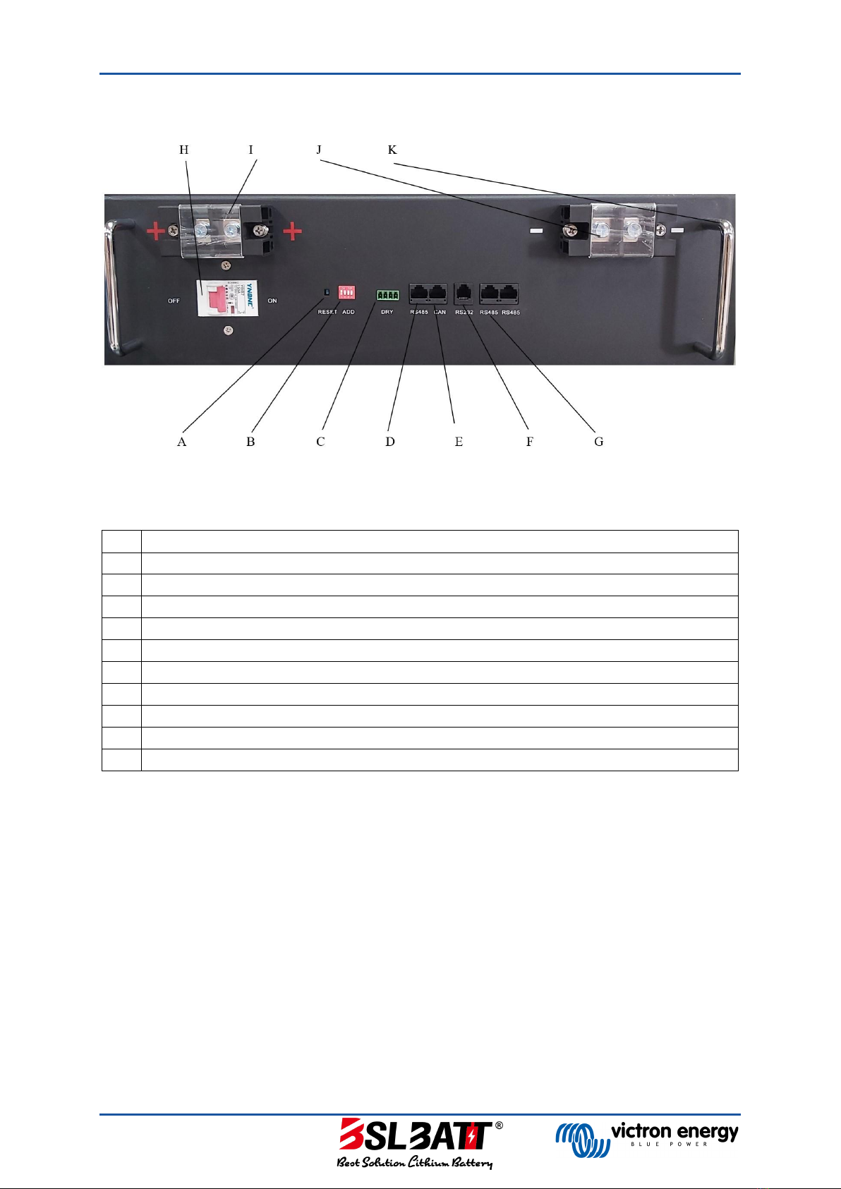
1. Pin-out Diagram .................................................................................................................................... 1
2. Battery Set-up........................................................................................................................................ 3
2.1 General........................................................................................................................................... 3
2.1.1 Turning battery on & O..................................................................................................... 3
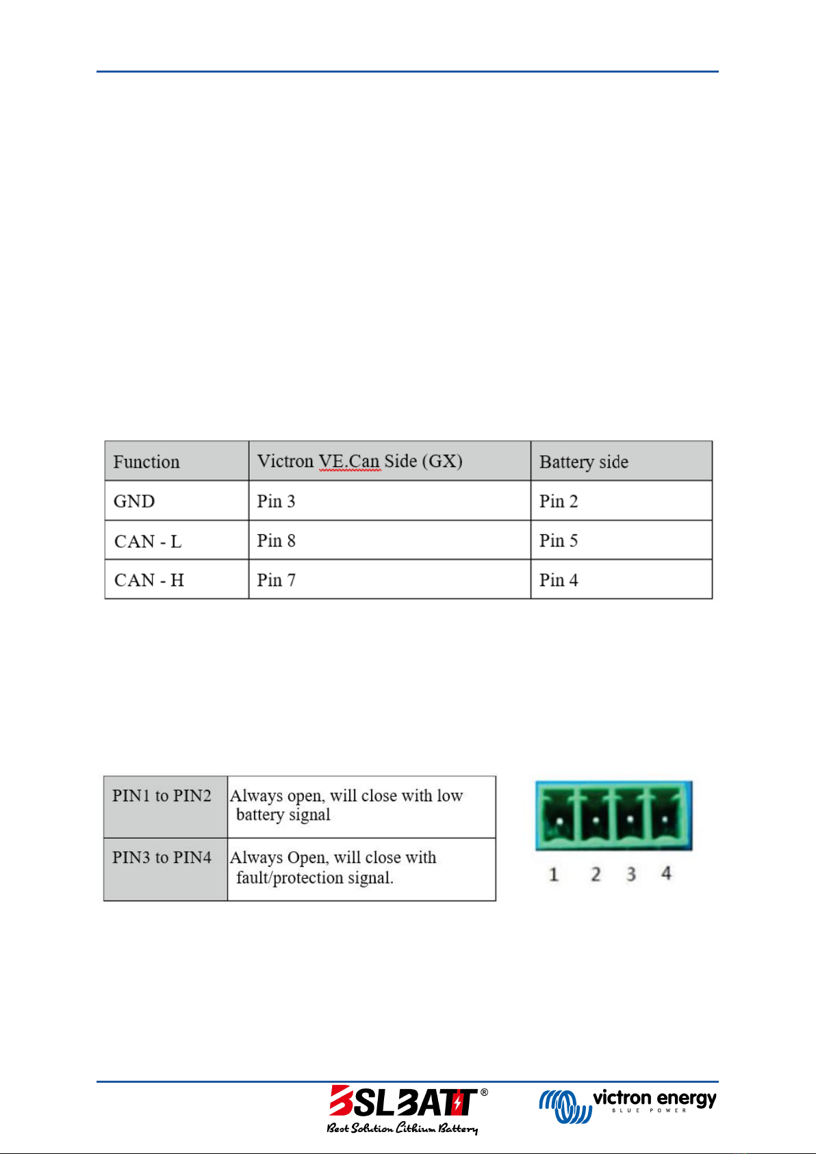
2.1.2 CAN Communication ........................................................................................................... 3
2.1.3 Dry Contacts.......................................................................................................................... 3
2.1.4 Other Ports............................................................................................................................ 3
2.2 Multiple Batteries ......................................................................................................................... 4
2.2.1 Max Number of Parallel Batteries ..................................................................................... 4
2.2.2 Installing Multiple Batteries................................................................................................ 4
2.2.3 Cable Sizing with Multiple Batteries.................................................................................. 4
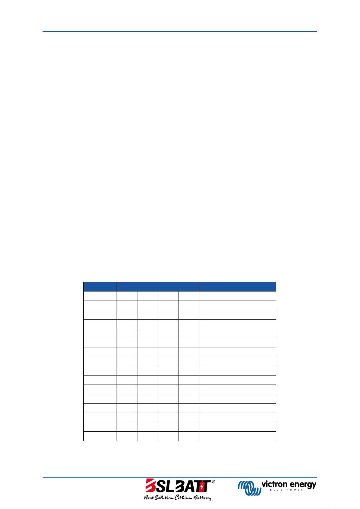
2.2.4 Dip Switch Settings for Multiple Batteries (5.1 kWh, 6.4 kWh, 10.2kWh) .................... 4
2.2.5 Dip Switch Settings for Multiple Batteries (8.2 kWh, 15 kWh)....................................... 5
3. Inverter Set-up....................................................................................................................................... 6
3.1 Batteries Per Inverter Size........................................................................................................... 6
3.1.1 5.1 kWh (100 Ah) .................................................................................................................. 6
3.1.2 6.4 kWh (125 Ah) .................................................................................................................. 6
3.1.3 7 kWh (135 Ah)...................................................................................................................... 6
3.1.4 8.2 kWh (160 Ah) .................................................................................................................. 6
3.1.5 8.8 kWh (172 Ah) .................................................................................................................. 7
3.1.6 10.2 kWh (200 Ah) ................................................................................................................ 7
3.1.7 15 kWh (300 Ah) ................................................................................................................... 7
3.2 Battery Set-up on Victron GX Device ......................................................................................... 8
3.3 Battery Set-up on Victron MPPT Device.................................................................................... 9
4. Inverter Settings (Victron).................................................................................................................. 10
4.1 General Tab ................................................................................................................................. 10
4.2 Grid Tab........................................................................................................................................ 11
4.3 Inverter Tab ................................................................................................................................. 12
4.4 Charger Tab................................................................................................................................. 13
4.5 Assistant Tab (a).......................................................................................................................... 15
4.6 Assistant Tab (b).......................................................................................................................... 16
4.7 Assistant Tab (c) .......................................................................................................................... 17
4.8 Assistant Tab (d).......................................................................................................................... 18
4.9 Assistant Tab (e).......................................................................................................................... 19
4.10 Assistant Tab (f)........................................................................................................................... 20
5. Revision History................................................................................................................................... 21