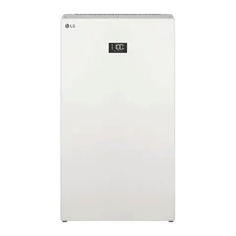
LG RESU3.3 User manual

Installation Manual for RESU LV
RESU3.3 (R4863P3S)
RESU6.5 (R48126P3S)
RESU10 (R48189P3S)
RESU PLUS
LG Chem strongly advises to take due care in following LGC’s product
installation manual. A warranty claim is invalid if damage is caused
by human error, inconsistent with the installation manual.
Version 2.4
Scan the QR code
[Installation Guide]

2
About this manual
This manual describes how to install LG Chem’s RESU®battery pack. Read this manual
before you attempt to install the product, and follow the instructions throughout the
installation process. If you are uncertain about any of the requirements, recommendations,
or safety procedures described in this manual, contact LG Chem immediately for advice and
clarication.
The information included in this manual is accurate at the time of publication. However, the
product specications are subject to change without prior notice. In addition, the illustrations
in this manual are meant to help explain system conguration concepts and installation
instructions. The illustrated items may dier from the actual items at the installation location.

3
Contents
1 Safety ................................................................................................................................. 6
1.1 Symbols on product labels.......................................................................................................6
1.2 Safety Instructions...................................................................................................................7
1.2.1 General Safety Precautions..........................................................................................................7
1.2.2 Battery Handling Guide...............................................................................................................8
1.3 Response to emergency situations...........................................................................................8
1.3.1 Leaking batteries..........................................................................................................................9
1.3.2 Fire ................................................................................................................................................9
1.3.3 Wet batteries.................................................................................................................................9
1.3.4 Damaged batteries......................................................................................................................10
1.4 Qualied installers................................................................................................................. 10
1.5 Contact information............................................................................................................... 10
2 Product Introduction..................................................................................................... 11
2.1 Technical Data ....................................................................................................................... 11
2.1.1 Dimensions and weight ..............................................................................................................11
2.1.2 Performance ...............................................................................................................................12
2.1.3 Charging cable requirements .....................................................................................................12
2.1.4 Network cable requirements ......................................................................................................12
2.1.5 Environmental requirements .....................................................................................................12
2.2 Feature.................................................................................................................................... 14
2.3 RESU lineup .......................................................................................................................... 15
2.4 RESU Plus..............................................................................................................................15
3 Installation Prerequisites .............................................................................................. 17
3.1 Installation materials ............................................................................................................. 17
3.2 Installation location ............................................................................................................... 17
3.3 Tools ....................................................................................................................................... 18
3.4 Safety gear ............................................................................................................................. 19
3.5 Making network cable ........................................................................................................... 19

4
4 Battery Pack Installation .............................................................................................. 21
4.1 Unpacking .............................................................................................................................. 21
4.2 Package items.........................................................................................................................22
4.3 Optional accessories ..............................................................................................................23
4.4 Checks before installation .....................................................................................................23
4.5 Installation clearance.............................................................................................................26
4.6 Securing battery pack to wall................................................................................................26
4.7 Cable connections ..................................................................................................................28
4.7.1 Connecting ground wire ............................................................................................................28
4.7.2 Connecting network cable..........................................................................................................29
4.7.3 Connecting power cables for RESU Plus ..................................................................................30
4.7.4 Connecting charging cables.......................................................................................................30
4.8 Finalizing installation............................................................................................................ 31
5 RESU Plus Installation.................................................................................................. 33
5.1 Unpacking ..............................................................................................................................33
5.2 Package items.........................................................................................................................33
5.3 Securing RESU Plus to wall..................................................................................................34
5.4 Cable connections.................................................................................................................. 35
5.4.1 Connecting charging cables......................................................................................................36
5.4.2 Connecting ground wires..........................................................................................................37
5.4.3 Connecting power cables ...........................................................................................................37
5.4.4 Connecting network cables........................................................................................................38
5.5 Finalizing installation............................................................................................................39
6 CongurationSwitches ................................................................................................. 40
6.1 Conguring Battery pack ......................................................................................................40
6.1.1 Setting for communication interface.........................................................................................40
6.1.2 Setting for battery cell type .......................................................................................................41
6.1.3 Settings for CAN bus pins .........................................................................................................41
6.1.4 Setting for terminal resistors .....................................................................................................41
6.2 Conguring RESU Plus.........................................................................................................42
6.2.1 Setting for communication interface.........................................................................................42
6.2.2 Settings for CAN bus pins .........................................................................................................42
6.2.3 Setting for terminal resistors .....................................................................................................42
Contents

5
Contents
7 Commissioning............................................................................................................... 43
7.1 Status indicators..................................................................................................................... 43
7.1.1 Battery pack................................................................................................................................43
7.1.2 RESU Plus ..................................................................................................................................44
7.2 Commissioning battery pack.................................................................................................44
7.3 Shutting down battery pack................................................................................................... 45
8 Troubleshooting.............................................................................................................. 46
9 FirmwareUpdate ........................................................................................................... 47
9.1 Updating battery pack rmware............................................................................................47
9.2 Updating RESU Plus rmware..............................................................................................49
10 Warranty......................................................................................................................... 50
11 Certications .................................................................................................................. 51
A CompatibleInverters..................................................................................................... 52
B SupportedMemoryCards ............................................................................................ 53

6
1 Safety
NOTE
To use rechargeable batteries, installers are required to comply with standard AS 4086.2
in Australia, VDE-AR-E2510-2 in Germany, and the domestic legislation in other
countries.
1.1 Symbolsonproductlabels
The nameplate is attached to the left side of the battery pack, and the warning label is
attached to the top.
CONNECTION KIT
ON
OFF
The voltage of this battery pack is strong enough to cause electric shock.
Make sure that the battery polarity is connected correctly.
Keep the battery pack away from open amer or ignition sources.
Keep the battery pack away from children.

7
Safety
Read the manual before installing and operating the battery pack.
The battery pack is heavy enough to cause severe injury.
The battery pack may leak corrosive electrolyte.
The battery pack may explode.
The battery pack should not be disposed of with household waste at the
end o s working life.
The battery pack should be disposed of at a proper facility for environmentally
safe recycling.
1.2 Safety Instructions
For safety reasons, installers are responsible for familiarizing themselves with the
contents of this manual and all warnings before performing installation.
1.2.1 General Safety Precautions
WARNING
Failure to observe the precautions described in this section can cause serious injury to
persons or damage to property.
Observe the following precautions:
• Risks of explosion
- Do not subject the battery pack to strong impacts.
- Do not crush or puncture the battery pack.
- Do not dispose of the battery pack in a re.
• Risks of re
- Do not expose the battery pack to temperatures in excess of 60°C.
- Do not place the battery pack near a heat source, such as a replace.
- Do not expose the battery pack to direct sunlight.
- Do not allow the battery connectors to touch conductive objects such as wires.

8
Safety
• Risks of electric shock
- Do not disassemble the battery pack.
- Do not touch the battery pack with wet hands.
- Do not expose the battery pack to moisture or liquids.
- Keep the battery pack away from children and animals.
• Risks of damage to the battery pack
- Do not allow the battery pack to get in contact with liquids.
- Do not subject the battery pack to high pressures.
- Do not place any objects on top of the battery pack.
1.2.2 BatteryHandlingGuide
• Use the battery pack only as directed.
• Do not use the battery pack if it is defective, appears cracked, broken or otherwise
damaged, or fails to operate.
• Do not attempt to open, disassemble, repair, tamper with, or modify the battery pack.
The battery pack is not user serviceable.
• To protect the battery pack and its components from damage when transporting,
handle with care.
• Do not impact, pull, drag or step on the battery pack. Do not subject it to any strong force.
• Do not insert foreign objects into any part of the battery pack.
• Do not use cleaning solvents to clean the battery pack.
1.3 Responsetoemergencysituations
The RESU battery pack comprises multiple batteries that are designed to prevent hazards
resulting from failures. However, LG Chem cannot guarantee their absolute safety.

9
1.3.1 Leakingbatteries
If the battery pack leaks electrolyte, avoid contact with the leaking liquid or gas. Electrolyte
is corrosive and contact may cause skin irritation and chemical burns. If one is exposed to the
leaked substance, do these actions:
Inhalation : Evacuate the contaminated area, and seek medical attention immediately.
Eye contact : Rinse eyes with owing water for 15 minutes, and seek medical attention
immediately.
Skin contact : Wash the aected area thoroughly with soap and water, and seek medical
attention immediately.
Ingestion: Induce vomiting, and seek medical attention immediately.
1.3.2 Fire
In case of a re, make sure that an ABC or carbon dioxide extinguisher is
nearby.
WARNING
The battery pack may catch re when heated above 150°C.
If a re breaks out where the battery pack is installed, do these actions:
1. Extinguish the re before the battery pack catches re.
2. If the battery pack has caught re, do not try to extinguish the re. Evacuate people
immediately.
WARNING
If the battery catches re, it will produce noxious and poisonous gases.
Do not approach.
1.3.3 Wet batteries
If the battery pack is wet or submerged in water, do not try to access it. Contact LG Chem or
your distributor for technical assistance.
Safety

10
1.3.4 Damagedbatteries
Damaged batteries are dangerous and must be handled with extreme caution. They are not
t for use and may pose a danger to people or property. If the battery pack seems to be
damaged, pack it in its original container, and then return it to LG Chem or your distributor.
CAUTION
Damaged batteries may leak electrolyte or produce ammable gas, If you suspect such
damage, immediately contact LG Chem for advice and information.
1.4 Qualiedinstallers
This manual and the tasks and procedures described herein are intended for use by skilled
workers only. A skilled workers is dened as a trained and qualied electrician or installer
who has all of the following skills and experience:
• Knowledge of the functional principles and operation of on-grid systems.
• Knowledge of the dangers and risks associated with installing and using electrical devices
and acceptable mitigation methods.
• Knowledge of the installation of electrical devices
• Knowledge of and adherence to this manual and all safety precautions and best practices.
1.5 Contact information
Use the contacts below for technical assistance. These phone numbers are available only
during business hours on weekdays.
Telephone Email
Europe +49 6196 5719 660 [email protected]
USA +1 888 375 8044 [email protected]
Australia +61 1300 178 064 [email protected]
Koreaandotherregions [email protected]
Safety

11
2 Product Introduction
2.1 Technical Data
2.1.1 Dimensionsandweight
RESU3.3 RESU6.5 RESU10 RESU Plus
Width 452 mm (17.80 in) 452 mm (17.80 in) 452 mm (17.80 in) 216 mm (8.50 in)
Height 120 mm (4.72 in) 120 mm (4.72 in) 227 mm (8.94 in) 120.5 mm (4.74 in)
Depth 402.5 mm (15.85 in) 655.5 mm (25.81 in) 484 mm (19.06 in) 156 mm (6.14 in)
Weight 131 kg (68.3 lb) 52 kg (114.6 lb) 75 kg (165.3 lb) 2 kg (4.4 lb)
1A battery pack’s weight varies slightly depending on its battery cells’ weight.
RESU10
452
227
484
452
RESU3.3
120
402.5
452
120
655.5
RESU6.5
ON
OFF
CONNECTION KIT
247
187
216 120.5
156
RESU Plus

12
2.1.2 Performance
RESU3.3 RESU6.5 RESU10
Nominal voltage 51.8 V 51.8 V 51.8 V
Operating voltage 42 to 58.8 V 42 to 58.8 V 42 to 58.8 V
Nominal capacity 63 A·h 126 A·h 189 A·h
Nominal energy 1) 3.3 kW·h 6.5 kW·h 9.8 kW·h
Standard power 1.1 kW 2.2 kW 3.3 kW
Maximum power 3 kW 4.2 kW 5 kW
Peak power for 3 seconds 3.3 kW 4.6 kW 7 kW
Peak current for 3 seconds 78.6 A 109.5 A 166.7 A
Maximum current 71.4 A at 42 V 100 A at 42 V 119 A at 42 V
Charge current 18.9 A 37.8 A 56.7 A
Discharge current 18.9 A 37.8 A 56.7 A
1) Actual usable energy at the AC output may vary by condition, such as inverter eciency
and temperature
If two battery packs are used, the nominal capacity and energy are equal to the sums of the
two, but the maximum and peak power are equal to those of RESU10.
Faradic charge eciency (25°C/77°F) 99%
Battery round-trip eciency (C/3, 25°C/77°F) 95%
Expected lifetime at 25°C/77°F More than 10 years
Communication interface CAN 2.0B
Cooling Natural convection
2.1.3 Chargingcablerequirements
Conductor cross-sectional area 33 to 50 mm2
Outer diameter 14 to 21 mm
Lug hole size M8
Lug width 21 mm
Maximum cable length 5 m per cable
2.1.4 Networkcablerequirements
Category Cat 5e
Connector 8P8C without any kind of boots
2.1.5 Environmentalrequirements
Available operating temperature −10 to 50 °C (14 to 122 °F)
Optimal operating temperature 15 to 30 °C (59 to 86 °F)
Storage temperature −30 to 60 °C (−22 to 140 °F)
Humidity 5 to 95% (non-condensing)
Altitude Below 2000 m (6562 ft)
Product Introduction

13
Product Introduction
• Short Circuit Current / Duration
RESU 10 RESUplus
Short Circuit Current 2.853kA 2.72kA
Duration 5ms 15ms
• Arc Flash Protection Calculations
In order to protect personnel from the possibility of being injured by an arc ash
hazard, Arc ash calculation of the battery system is estimated with the Incident Energy
Calculations refer to Annex D of NFPA 70E.
RESU 10 RESUplus
Battery System Voltage 58.8V 58.8V
Battery System Internal Resistance 0.0206Ω 0.0216Ω
Bolted Fault Current 2.853kA 2.72kA
Arcing Current 1.4265kA 1.36kA
Clearing Time 4ms 5ms
Arc Flash Incident Energy 0.0015 Cal/cm20.0018 Cal/cm2
Working Distance 450mm(18inch) 450mm(18inch)
Battery system installers must wear PPE(Personal Proactive Equipment) according to
NFPA 70E Article 130, referring to the calculation results above.
WARNING
• When install the battery system, the worker shall wear arc-rated clothing in every occasions and
places to protect him/her from any possible exposure to an electric arc ash.
• The arc-rated clothing that the worker is wearing must assure the worker’s movement and visibility
while covering all ignitable clothing.
• The worker shall wear the non-conductive safety helmet every occasions and places to protect him/
her from any danger of head injury from electric shock or burns due to the contact with energized
electrical conductors or circuit parts resulting from electrical explosion.
• The worker shall wear non-conductive protective equipment for the face, neck, and chin in every
occasions and places to protect him/her from any danger of injury from exposure to electric arcs or
ashes resulting from electrical explosion.
• The worker shall wear non-conductive protective equipment for the eyes in every occasions and
places to protect him/her from any danger of injury from electric arcs, ashes resulting from
electrical explosion.
• The worker shall wear hearing protection within the arc ash boundary.
• The worker shall wear Heavy-duty leather gloves or arc-rated gloves, satisfying the following
regulation level, for arc ash protection. In the case of wearing the rubber gloves for the shock
protection, he/she shall wear additional leather protectors above the gloves.
• The worker shall wear Heavy-duty leather footwear or dielectric footwear or both to provide some
arc ash protection.
• The worker shall inspect Arc-rated apparel before every use.
• Work clothing or arc ash suits that are contaminated or damaged to the extent, impairing the
protective qualities, shall not be used.
• Protective items that become contaminated with grease, oil, or ammable liquids or combustible
materials shall not be used.
• The garment manufacturer's instructions for care and maintenance of arc-rated apparel shall be
followed.
• Arc-rated apparel shall be stored in a manner that prevents physical damage;damage from moisture,
dust, or other deteriorating agents or contamination from ammable or combustible materials.

14
2.2 Feature
The RESU®battery pack has the following features:
Energystorageunit: This battery pack is designed for domestic photovoltaic system
compatibility.
Batterymanagementsystem(BMS): The battery pack’s built-in BMS monitors
its operation and prevents the battery from operating outside design limitations. See
Troubleshootingonpage46.
Easyrmwareupdate: The BMS rmware can be updated to the latest version. See
FirmwareUpdateonpage47.
Expandability:The battery capacity can be increased by adding another battery pack.
See RESU Plus onpage15.
Product Introduction

15
Product Introduction
2.3 RESUlineup
There are three RESU battery pack models.
ON
OFF
CONNECTION KIT
ON
OFF
CONNECTION KIT
ON
OFF
CONNECTION KIT
RESU3.3 RESU6.5 RESU10 RESU13
For details about these models, see Technical data onpage11.
2.4 RESU Plus
The RESU battery pack can be used in combination of up to 2 units.
• RESU3.3 + RESU3.3
• RESU3.3 + RESU6.5
• RESU3.3 + RESU10
• RESU6.5 + RESU6.5
• RESU6.5 + RESU10
• RESU10 + RESU10
• RESU13 + RESU13
(only RESU13s can be used in combination)
ON
OFF
CONNECTION KIT
A unit of RESU Plus, which is sold separately, is required to install two RESU battery packs.
Two battery packs are connected to an inverter via a RESU Plus.

16
Product Introduction
2
3 4
1
1) 1st battery pack 2) 2nd battery pack
3) RESU Plus 4) Inverter
Use this procedure to install two battery packs using the RESU Plus.
1. Secure the RESU Plus to the wall.
2. Secure two battery packs to the wall.
3. Connect power and network cables to the RESU Plus.
4. Connect the power and network cables to the inverter.
5. Connect the power and network cables to the battery packs.

17
3 Installation Prerequisites
3.1 Installation materials
These installation materials shall be prepared by installers.
• Charging cable
• Network cable
• Ground wire
• RJ45 plug
• Silicone sealant or putty
NOTE
Make sure that the cross-sectional area of charging cables is 33 to 50 mm2.
3.2 Installation location
Make sure that the installation location meets the following conditions:
• The building is designed to withstand earthquakes.
• The location is far away from the sea, to avoid salt water and humidity.
• The oor is at and level.
• There are no ammable or explosive materials nearby.
• The optimal ambient temperature is between 15 and 30°C.
• The temperature and humidity stays at a constant level.
• There is minimal dust and dirt in the area.
• There are no corrosive gases present, including ammonia and acid vapor.
NOTE
The RESU battery pack is rated at IP55 and thus can be installed outdoors as well as
indoors. However, if installed outdoors, do not allow the battery pack to be exposed to
direct sunlight and moisture.
NOTE
If the ambient temperature is outside the operating range, the battery pack stops
operating to protect itself. The optimal temperature range for the battery pack to
operate is 15°C to 30°C. Frequent exposure to harsh temperatures may deteriorate the
performance and lifetime of the battery pack.

18
Installation Prerequisites
3.3 Tools
These tools are required to install the battery pack.
14
14
14
Torque screwdriver Phillips-screwdriver bit Hex-key bit
14
14
14
Phillips-head screwdriver Flat-head screwdriver Torque wrench
14
14
14
Wire stripper Cable crimper Voltmeter
14
14
14
Tape measure Drill Sealant gun
Use properly insulated tools to prevent accidental electric shock or short circuits.
Use adjustable tools and measuring instruments that are certied for precision and accuracy.

19
Installation Prerequisites
3.4 Safetygear
Wear the following safety gear when dealing with the battery pack. Installers must meet
the relevant requirements of international standards, such as IEC 60364 or the domestic
legislation.
Insulated gloves Safety goggles Safety shoes
3.5 Makingnetworkcable
Use this method to make a network cable, which is to be connected between the battery pack
and the inverter or the RESU Plus.
1. Cut network cable to the needed length.
2. Strip 2.5 to 5 cm of the outer sheath at one end of the cable.
3. Untwist and separate each pair of wires.
4. Arrange the wires in this order:
1) White with an orange stripe
2) Orange
3) White with a green stripe
4) Blue
5) White with a blue stripe
6) Green
7) White with a brown stripe
8) Brown

20
5. Bring the sorted wires together, and trim them to about 1.4 cm in length.
6. Hold the RJ45 plug with the copper contacts facing up, and insert the wires into the plug,
making sure that they stay aligned and each color goes into its appropriate channel.
7. Put the plug into a cable crimper and squeeze the handles thoroughly.
8. If available, use a LAN cable tester to see if the cable is faulty.
Repeat these steps for the other end of the cable.
Installation Prerequisites
This manual suits for next models
6
Table of contents
Other LG Batteries Pack manuals