LG C2500 User manual

Service Manual Model : C2500
Date: February, 2006 / Issue 1.0
Service Manual
C2500

Service Manual
Personal Cellular Telephone
C2500
Every care has been taken to ensure that contents of this service manual give an accurate representation of
the equipment. However, DARTS TECHNOLOGIES CORP. accepts no responsibility for inaccuracies which
may occur and reserves the right to make changes to the design without prior notice.
WARNING
This service information is designed for experienced repair technicians only and is not designed for use by the general public.
It does not contain warnings or cautions to advise non-technical individuals of potential dangers in attempting to service a
product. Products powered by electricity should be serviced or repaired only by experienced professional technicians. Any
attempt to service or repair the product or products dealt with in thes service information by anyone else could result in
serious injury or death.

1. INTRODUCTION.......................................5
1.1 Purpose of the Manual ................................... 5
1.2 Structure of the Manual....................................5
1.3 Servicing Responsibilities ................................5
2. LEVEL 2.5 SERVICE GUIDELINES.........6
2.1 Introduction ......................................................6
2.2 Level of Repair Guidelines...............................6
2.3 Level of Repair Service Tools and Interfaces ..9
2.4 Features...........................................................9
2.5 Mobile Unit Basic Kit ......................................10
3. OPERATING INSTRUCTIONS ...............11
3.1 General ..........................................................11
3.2 Liquid Crystal Display.....................................11
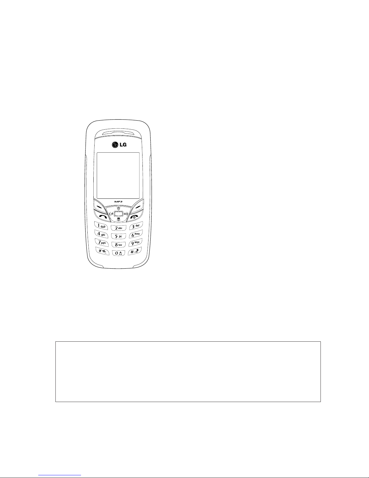
3.3 Location of Controls .......................................13
3.4 Alpha Entry.....................................................14
3.4.1. Character Set / Key Assignments...........14
3.5 Public Man Machine Interface (MMI) .............16
3.5.1. Reading the Phonebook
Memory Location ....................................16
3.5.2. Features for Factory Service ..................16
3.5.3. Tips for Call Option.................................18
3.6 Security Procedure.........................................18
3.7 Troubleshooting .............................................19
4. ASSEMBLY INSTRUCTIONS.................20
4.1 Assembly Structure........................................20
4.2 Antenna sub assembly...................................21
4.3 PCB sub assembly.........................................22
4.4 Top case sub assembly .................................25
4.5 Bottom case sub assembly ............................25
4.6 Main assembly ...............................................27
5. TECHNICAL SPECIFICATION ...............30
5.1 TX Characteristics..........................................30
5.1.1. Frequency Error......................................30
5.1.2. Modulation Phase Error..........................30
5.1.3. Output RF Spectrum due to Modulation .30
5.1.4. Output RF Spectrum due to Switching
Transients ...............................................30
5.1.5. Spurious Emissions at Antenna
Connector ...............................................31
5.1.6. Residual Peak Power .............................33
5.2 Rx Characteristics..........................................34
5.2.1. Sensitivity................................................34
6. Calibration .............................................37
7. BLOCK DIAGRAM .................................44
7.1 C2500 Base band Hardware Typical application
and Block Diagram.........................................44
7.2 C2500 RF Block Diagram ..............................46
8. C2500 PCB PLACEMENT......................47
9. CIRCUIT DIAGRAM ...............................49
10. REPLACEMENT PART LIST................57
CONTENTS

- 3 -
IMPORTANT
This document is intended for use by qualified service personnel only.
Our policy is of continuous development; details of all technical modifications will be included with
service bulletins.
While every endeavor has been made to ensure the accuracy of this document, some errors may
exist. If any errors are found by the reader, please notified it to company

- 4 -
Warnings and Cautions
Please refer to the phone’s user guide for instructions relating to operation, care and maintenance
including important safety information. Note also the following:
Warnings:
1. CARE MUST BE TAKEN ON INSTALLATION IN VEHICLES FITTED WITH ELECTRONIC ENGINE
MANAGEMENT SYSTEMS AND ANTI-SKID BRAKING SYSTEMS. UNDER CERTAIN FAULT
CONDITIONS, EMITTED RF ENERGY CAN AFFECT THEIR OPERATION. IF NECESSARY,
CONSULT THE VEHICLE DEALER/MANUFACTURER TO DETERMINE THE IMMUNITY OF
VEHICLE ELECTRONIC SYSTEMS TO RFENERGY.
2. THE HANDPORTABLE TELEPHONE MUST NOT BE OPERATED IN AREAS LIKELY TO
CONTAIN POTENTIALLY EXPLOSIVE ATMOSPHERES EG PETROL STATIONS (SERVICE
STATIONS), BLASTING AREAS ETC.
3. OPERATION OF ANY RADIO TRANSMITTING EQUIPMENT, INCLUDING CELLULAR
TELEPHONES, MAY INTERFERE WITH THE FUNCTIONALITY OF INADEQUATELY
PROTECTED MEDICAL DEVICES. CONSULT A PHYSICIAN OR THE MANUFACTURER OF THE
MEDICAL DEVICE IF YOU HAVE ANY QUESTIONS. OTHER ELECTRONIC EQUIPMENT MAY
ALSO BE SUBJECT TO INTERFERENCE.
Cautions:
1. Servicing and alignment must be undertaken by qualified personnel only.
2. Ensure all work is carried out at an anti-static workstation and that an anti-static wrist strap is worn.
3. Ensure solder, wire, or foreign matter does not enter the telephone as damage may result.
4. Use only approved components as specified in the parts list.
5. Ensure all components, modules screws and insulators are correctly re-fitted after servicing and
alignment. Ensure all cables and wires are repositioned correctly.

1. INTRODUCTION
- 5 -
1.1. Purpose of the Manual
This service manual contains the information and procedures required for instilling, operating and
servicing the LG GSM Personal Cellular Mobile Telephone system operating on GSM Digital Cellular
Networks.
1.2. Structure of the manual
The manual is structured to provide service engineering personnel with the following information and
procedures:
1. General and technical information - provides a basic understanding of the equipment, kits and
options, together with detailed information for each of the major component parts.
2. Installation and operating information - provides instructions for unpacking, installing and operating
the equipment.
3. Servicing information - provides complete instructions for testing, disassembly, and reassembly of
the product. Step-by-step troubleshooting information is given to enable the isolation and
identification of a malfunction, and thus determine what corrective action should be taken. The test
information enable verification of the integrity of the equipment after any remedial action has been
carried out.
4. Illustrated parts list - provides to enable the identification of all cosmetic and some electrical
components, for the ordering of replacement parts.
1.3. Servicing Responsibilities
The procedures described in this manual must performed by qualified service engineering personnel,
at an authorized service center.
The service engineering personnel are responsible for fault diagnosis and repair of all equipment
described in this manual.
1. INTRODUCTION

2. LEVEL 2 SERVICE GUIDELINES
- 6 -
2.1. Introduction
The document is intended to help you carry out repair up to Level 2 on the C2500 mobile phone.
The repair for International version and Asian variants are identical unless otherwise noted, therefore
the description herein is confined to C2500 only.
2.2. Level of Repair Guidelines
The following description provides an outline of the level of repairs that could be determined at
customers’ premises. The level of repairs are highly dependent on the customer’s resource and
capabilities and are approved by
2.2.1. Level 0
This level DO NOT involved any kinds of repair or disassembly of the mobile unit. The customer ONLY
needs to identify the fault occurred and send back the faulty units with the fault report to DARTS
Mobile Service Center The inventory swap units are available for order.
Level 0 Part No.
2.2.2. Level 1
This level requires the repair or disassembly of the mobile unit up to a certain specified criteria. This
level might requires a specific tools in conducting the Level 1 repair job. All components attached to
the upper and lower casings are replaceable.
2. LEVEL 2 SERVICE GUIDELINES
All repairs have to be carried out in an environment set up
according to ESD regulations defined in international standards.
Please abide by your service contract agreements in determining
the level of repairs that you are capable of conducting.
Only qualified personnel shall perform all the related repair
procedures based on the service contract
DARTS P/N Description SVC Level LG P/N
2284-1870-6000 Swap Unit Complete, C2500 L0

2. LEVEL 2 SERVICE GUIDELINES
- 7 -
DO NOT remove any components on the PCB board.
If the repaired units still DO NOT function properly, customer needs to attach the fault report together
with the units complete with housings and send back to DARTS Mobile Service Center for further
investigations. The components listed below are intended for Level 1 repair spares only.
Level 1 Part No.
2.2.3. Level 2
This level of repair requires the exchange of the mobile unit main board. There will be non-removal of
any components on the faulty main board. The exchanged faulty main boards shall be properly packed
in a plastic bulk with the attached IMEI label and fault report and send back to DARTS Mobile Service
Center for detailed repairs.
DARTS P/N Description SVC Level LG P/N
2207-0030-0003 Vibrator 3V L1 SJMY0007009
228S-2187-0010 BOTTOM CASE Ass'y Silver L1 ACGM0071701
221C-BA03-0102 Battery connector Pitch=2.5mm 3Pin PA08303 L1 ENZY0018701
2285-3187-0000 Antenna Ass'y ( w Louder SPK) L1 SNGF0013601
2206-1110-0001 Receiver Panasonic - EASG1D501E2 L1 SURY0009301
228S-1187-0000 TOP CASE Ass'y LG Silver ( w LENS) L1 ACGK0073101
2211-DP18-1100 Deco. Plate for Side-L L1 MDAC0017601
2211-DP18-2100 Deco. Plate for Side-R L1 MDAC0017701
2211-SE18-0100 SIDEKEY 1 WAY L1 MBJL0032901
2211-SE18-1100 SIDEKEY 2 WAY L1 MBJN0008401
2218-1800-6280 Keypad RUS Silver L1 ABGA0006901
2212-DM18-0000 Metal dome L1 ADCA0051201
2206-5030-0083 MIC. FPT-22718-3 L1 SUMY0005604
2211-BA18-0100 Battery Cover LG L1 MCJA0032301
2213-TR18-0100 RF_SW_CAP rubber Grey L1 MCCF0035601
2214-MF13-3Z80 Screw (M1.6*3.8)°AZN°AWhite L1 GMZZ0020401
2213-TR18-1100 PHONE JACK CAP L1 MCCC0036001
2213-TR18-2100 USB CAP L1 MCCE0029101
225N-TM03-3280 SENSOR VGA TM03-E1-X10 L1

2. LEVEL 2 SERVICE GUIDELINES
- 8 -
Level 2 Part No.
2.2.4. Level 2.5
This level requires the repair or removal of certain specified discrete components of the mobile units’
main board. This level of repair might requires a specific tools and soldering equipments with proper
soldering jigs in conducting the repair job.
Level 2.5 Part No.
DARTS P/N Description SVC Level LG P/N
2218-18B5-0080 PCB Main Board, C2500 L2 SAFY0159101
ONLY THE QUALIFIED PERSONNEL SHALL BE LIABLE TO
PERFORM THIS LEVEL OF REPAIRS UNDER THE SUPERVISION
AND APPROVAL OF DARTS TECHNICAL TRAINER.
DARTS P/N Description SVC Level LG P/N
2221-1341-0082 LCM STN 128x128dot 26P LKC34TML8Y L2.5 SVLY0027001
220B-0010-0000
BACKUP BATT D4.8Xh1.4mm 0.06F XC414-II06
L2.5 SBCL0001003
220S-1020-0081 SIDE KEY 20MA/12V 6P L2.5 ESCY0004301
220S-2010-0081
RF TEST SWITCH 6000MHz 2W 50 OHM MS156
L2.5 ENWY0004101
2212-BC18-0000 BASE BAND COVER FOR ARI L2.5 MCBA0011201
2212-BF18-0000 BASE BAND FRAME FOR ARI L2.5 MCBA0011202
2212-RC18-0000 RF COVER FOR ARI L2.5 MCBA0011301
2212-RF18-0000 RF FRAME FOR ARI L2.5 MCBA0011302
221C-SC06-0182
SIM CARD CONN PITCH=2.54mm 6P 217-010-60 L2.5 ENSY0017201
221C-SP02-0186
SPEK CONN P=3mm 2P CBE-2809-2258H POGOPI
L2.5 ENZY0018401
221C-PG01-0181 POGO PIN 1P CDR-5815-2961 L2.5 ENZY0018501
221J-EP06-0988 EARPHONE JACK 6P L2.5 ENJE0005101
221C-IN05-0185 MINI USB CONN 5P US25R05-SBP L2.5 ENRY0006201
2265-3010-0582 LED R G B HT-372FCH-DT L2.5 EDLS0001001
221C-sk20-0186 Socket 20p CLE9020-0102F L2.5 ENSY0017301

2. LEVEL 2 SERVICE GUIDELINES
- 9 -
2.3. Level of Repair Service Tools and Interfaces
This section provides an overview of the necessary equipments and tools to conduct the specified
levels of repair job accordingly.
The service interface is used for the purpose of communicating with the mobile unit in situation such
as software upgrading and testing process. These service interfaces are listed below:
2.4. Features
The LG Telephone Model C2500 is a high performance small, light handset for business and domestic
use. The following features are provided:
1. Triple Codec which includes Half Rate / Full Rate and Enhanced Full Rate (EFR) speech codec.
2. Tri Band E-GSM900 and DCS1800 operation.
3. GPRS Service.
4. T9 Text Entry.
Level of Repairs Tools & Equipments DARTS P/N LG P/N
0Not required
1
ESD Strap, Tweezer, Power Drill, Air blower,
Flux remover, Disassembly tool, Digital Multimeter
2ESD Strap
As in Level 1 with additional equipment: Soldering and
2.5 desoldering station, Flux paste, Solder wick, Solder lead,
C2500 soldering jigs, CTS 55 GSM Tester, C2500 Testing
jigs, Power supply
DO NOT INTEND TO REMOVE ANY ACTIVE COMPONENTS AS
THIS WILL CAUSE THE MAIN BOARDS TO MALFUNCTION AND
BEYOND THE REPAIR BOUNDARIES
DARTS P/N Description SVC Level LG P/N
RF Cable L2.5
SW D/L cable : ALL

2. LEVEL 2 SERVICE GUIDELINES
- 10 -
5. Voice Ringer.
6. Wireless Application Protocol (WAP) Browser.
7. Backup Battery.
8. Downloadable polyphonic melody ring tones.
9. Clock, Calculator and Currency Converter.
2.5. Mobile Unit Basic Kit
Figure 2.1: Hand portable Main Unit Kit Content
Item Description Part Number
1Handset 2284-1870-A000
2AC Travel Charger 2237-22T0-1003
3Standard Battery (Li-lon 720mAh) 220A-0307-1000

3. OPERATING INSTRUCTIONS
- 11 -
3.1. General
This section provides a brief guide to the operation and facilities available on the telephone handset.
Refer to the Operating Instruction supplied with the telephone for full operational information.
3.2. Liquid Crystal Display
The telephone handset has a graphical chip on glass display. The following icons are available:
1. Top of the screen shows Essential Indicators. (See table below)
2. Next line displays the operator name
3. shows date/time.
4. To enter Menu press left selection key.
5. To use Name in the phone book press right selection key.
3. OPERATING INSTRUCTIONS
Figure 3.1: Crystal Display

3. OPERATING INSTRUCTIONS
- 12 -
Essential indicators
Indicates signal strength and alternate line service.
Shows handset current battery charge strength.
Indicates the phone keypad is locked.
Indicates the profiles alert type is Ring
Indicates the profiles alert type is vibration.
Indicates the profiles alert type is vibration and ring.
Indicates the profiles alert type is vibration then ring.
Indicates the profiles alert type is light only.
The Alarm clock is set on.
Indicates “roaming”.
Indicates missed call.
Indicates Broadcast set on.
Indicates new text messages.
Indicates call diverted is set on
Indicates record function on

3. OPERATING INSTRUCTIONS
- 13 -
3.3. Location of Controls
Figure 3.2: Location of Controls
Hand-free kit connection
Adjust Volume Side key
Power on / charging indicator
B
D
USB connector
Antemma area
Earpiece
Audio Play
Display Screen
C
B
A
Microphone
Speaker
Battery Cover

3. OPERATING INSTRUCTIONS
- 14 -
3.4. Alpha Entry
3.4.1. Character Set / Key Assignments
There are 20 keys on C2500, including 0, 1, 2, 3, 4, 5, 6, 7, 8, 9, *, #, SEND, END, Left-Soft-Key
(LSK), Right-Soft-Key (RSK), 4-way Navigation Key.
The following ID drawing is only used for Keypad Layout’s reference.
Figure 3.3:C2500 Keypad Layout

3. OPERATING INSTRUCTIONS
- 15 -
➢ Key Function List
λ A. Power/End key.
• Switch phone on and off. Also, ends a call or Exit from any function and back to Idle mode.
λ B. Selection Key
• The function of the keys depends on the text shown on the display above the keys.
For example, Menu and Name in Idle mode.
λ C. Navigation Key
• Use for quick access to phone functions in Idle mode.
♦Up key: Access to the Favorites menu.
♦Down key: Access to the Phone book menu
♦Left key: Access to the Profiles menu
♦Right key: Access to the Messages menu
• Scroll through names and numbers stored in the phone book or through the phone’s menus,
submenus, and option list.
λ D. Send/Answer Key
• Make and answer calls; press in Idle mode to see recent dialed calls.
• 0-9 input number and character
λ E. Left Side Key
• Adjust handset volume
λ F. MP3 Play Key
• The shortcut to enter audio player in Idle mode.
• The capture key to take picture in camera mode.

3. OPERATING INSTRUCTIONS
- 16 -
3.5. Public Man Machine Interface (MMI)
3.5.1. Reading the Phonebook Memory Location
# <MEMORY LOCATION> #
Leading zeros can be left out of the location number, e.g. 007 can be 7.
3.5.2. Features for Factory Service
Features Description
By 2945#*# to enter production mode
A. Version[1]
This displays the version of each item.
• Version Info Summary: The software version.
• MCU SW: The protocol Version.
• Melody: Melody version.
• Serial No: Phone Serial number.
• BB Chip: Base band chipset version.
• DSP Code: DSP code compile time.
• DSP Patch: DSP patch version.
• MS Board: MS board version.
Production or service mode • Build No: The SW build time.
B. Resource BIN[2]
This displays the resource BIN of each item.
• AUDIO: The audio resource BIN Version.
• IMAGE: The image resource BIN Version.
• STR: The string resource BIN Version.
• FONT: The font resource BIN Version
C. Echo loop[3]
This menu is to test the analog loop back path from MIC to Receiver.
D. Keypad[4]
This menu is to test all Keypad keys.
E. Vibrator[5]
This menu is to test the Vibrator.
F. Loud Spk[6]
This menu is to test the Loud Speaker.

3. OPERATING INSTRUCTIONS
- 17 -
G. Ring tone[7]
This menu is to test the Ring tone.
H. LED[8]
This menu is to test the LED.
• Main LCM BL on: Main LCM BL is on.
• Main LCM BL off: Main LCM BL is off.
• Keypad LED on: Keypad LED is on.
• Keypad LED off: Keypad LED is off.
I. LCD[9]
This menu is to test primary colors of LCD Module.
J. LCD contrast[10]
This menu is to set the LCD contrast.
• Main LCD [10-1]: Change this value by up and down key.
K. Receiver[11]
This menu is to test the Receiver.
L. Charger[12]
This displays all the ADC values.
• VBAT: Main Battery Voltage.
• BTemp: Battery Temperature.
• VAUX: Headset hook detection voltage.
• Current: Charging current.
• VChgr: Charging voltage.
M. Headset[13]
This menu is to test the analog loop back path from headset MIC to
headset Receiver.
N. RTC[14]
This menu is to test the real time clock. Set a 3-second alarm and
Switch off the MS. After the alarm expires, the MS will power on
automatically.
O. Nand Flash[17]
This menu is to test the Nand flash.
P. CAMERA[18]
This menu is the test Camera module by picture preview and
parameter setting.
Display IMEI By *#06#
Reset to default language *#0000#[SEND]
Set language to Russian *#0007#[SEND]
Set language to English *#0044#[SEND]

3. OPERATING INSTRUCTIONS
- 18 -
3.5.3.Tips for Call Option
A call can be connected to any single caller by pressing Option key. When user press Option key
during active call, user can choose one of those functions from the list:
Hold: put a call on.
Retrieve: reconnect a holding call.
Retrieve All: reconnect all holding call.
Swap: switch between the call on hold and active.
Conference: make a multi-party conversation.
Transfer: transfer a call.
Spilt: to suspend the multi-party call.
End Single: end one of conference call.
End All: end a multi-party call.
End: End a call.
Mute: mute the call during the conversation.
New Call: make a new call during an active call.
Phonebook: shortcut to phonebook menu.
SMS: shortcut to Message menu.
Sound Recorder: shortcut to Sound Recorder submenu.
DTMF: set On / Off for DTMF (Dual Tone Multi-Frequency) tone dialing system.
3.6. Security Procedure
Features Description
PIN 1 and 2 PIN activate, changing and deactivation
PIN control Menu entry to change PIN2/phone code
Phone code
Manufacture defined codes to protect
phone (4 - 8 digits). Changeable by user.
FDN Fixed Dialled Number for limited Dialling
BDN Barred Dialled Number for limited Dialling

3. OPERATING INSTRUCTIONS
- 19 -
3.7. Troubleshooting
The user is given the following information and advised to contact the dealer if the problems persist:
Problem Cause Remedy
Telephone will not Check that the battery pack is fully charged
switch on and correctly connected to the telephone.
Extremely short battery The network in use and the Avoid areas of poor reception. Ensure
life for a new battery condition of the battery pack batteries are fully charged.
pack can affect battery life.
Short battery life for an The battery pack was worn Replace with a new one.
old battery pack out.
The battery level If a battery is deeply Leave to charge for several minutes in
indicator does not discharged it will take a short temperatures between +5°C and + 35°C.
light when charging time before there is sufficient
owner in the telephone to
light the battery level
indicator .
Calls cannot be made The telephone is locked. Unlock the telephone
(Menu: Security: Phone Lock).
Outgoing calls are barred. Disable the outgoing call barring (Menu:
Security: Call Bar).
The telephone is not Move to a coverage area and operate the
registered to a network. telephone after it has registered with a network.
Calls cannot be made Check that SIM supports Fixed Dial Check
from Fixed Dial Store if the Fixed Dial is switched on (Menu:
Security: Fixed Dial). Check the telephone
number is stored in the Fixed Dial.
Calls cannot be received The telephone is not Switch the telephone on.
switched on.
Incoming calls are barred. Disable the incoming call barring (Menu:
Security: Call Bar).
The telephone is not Move to a coverage area and operate the
registered to a network. telephone after it has registered with a
network.
Emergency calls cannot User’s phone is not in a Check that the antenna symbol is
be made GSM coverage area. displayed. Move to coverage are and
operate the telephone when the antenna
symbol is displayed.
Telephone umbers The telephone is locked. Unlock the telephone (Menu: Security:
Cannot be recalled Phone Lock).
Fixed Dial is switched on Switch off Fixed Dial (Menu: Security:
Fixed Dial).
Other manuals for C2500
1
Table of contents
Other LG Cell Phone manuals