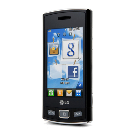
LG Chocolate KE800 User manual

Service Manual Model : KE800
Service Manual
KE800
Date: January, 2007 / Issue 1.0

- 3 -
The information in this manual is subject to change without notice and should not be construed as a
commitment by LGE Inc. Furthermore, LGE Inc. reserves the right, without notice, to make changes to
equipment design as advances in engineering and manufacturing methods warrant.
This manual provides the information necessary to install, program, operate and maintain the KE800.
REVISED HISTORY
DATE ISSUE CONTENTS OF CHANGES S/W VERSION
13 DEC 2006 ISSUE 1 Initial Release

- 4 -

- 5 -
1. INTRODUCTION ...............................7
1.1 Purpose .................................................. 7
1.2 Regulatory Information............................ 7
1.3 ABBREVIATION ..................................... 9
2. PERFORMANCE .............................11
2.1 Hardware Features ................................11
2.2 Technical Specification ..........................12
3. TECHNICAL BRIEF ........................15
3.1 Quad-Band RF EDGE Transceiver
(PMB6272, U602) ..................................15
3.2 Power Amplifier Module (PAM :
SKY77340, U502) ..................................18
3.3 26 MHz Clock (VCTCXO, X601)............19
3.4 Front End Module for Triband
(YGHF-S006T, FL601)...........................19
3.5 Baseband Chip(PMB8876, U101)..........22
3.6 Audio......................................................23
4. Trouble Shooting ...........................25
4.1 Main & Sub PCB Components
Placement ..............................................25
4.2 Key PCB Components Placement.........28
4.3 FPCB Components Placement ..............29
4.4 Power On Trouble..................................30
4.5 Charging Trouble ...................................33
4.6 LCD Display Trouble..............................36
4.7 Camera Trouble .....................................38
4.8 Speaker Trouble ....................................40
4.9 Receiver Trouble....................................42
4.10 Microphone Trouble .............................43
4.11 Vibrator Trouble ...................................45
4.12 Keypad Backlight Trouble (EL driver) ..47
4.13 SIM Detect Trouble ..............................49
4.14 Bluetooth Trouble.................................51
4.15 FM Radio trouble .................................53
4.16 TOUCH PAD Trouble shooting ............55
4.17 Multimedia Microphone Trouble...........58
4.18 18pin Multi-Port Receptacle.................60
4.19 RF PART TROUBLESHOOTING ........64
5. Block Diagram................................77
5.1 Power Block Diagram ............................78
6. SW Download ....................................79
6.1 Download setup .....................................79
6.2 Download procedure..............................80
7. CIRCUIT DIAGRAM ........................85
8. PCB LAYOUT..................................97
9. CALIBRATION ..............................109
9.1 Calibration test equipment setup .........109
9.2 Calibration procedure...........................110
10. EXPLODED VIEW &
REPLACEMENT PART LIST ......115
10.1 Exploded View .................................. 115
10.2 Replacement Parts ............................117
10.3 Accessory ......................................... 141
Table Of Contents

- 6 -

1. INTRODUCTION
- 7 -
1.1 Purpose
This manual provides the information necessary to repair, calibration, description and download the
features of the KE800.
1.2 Regulatory Information
A. Security
Toll fraud, the unauthorized use of telecommunications system by an unauthorized part (for example,
persons other than your company’s employees, agents, subcontractors, or person working on your
company’s behalf) can result in substantial additional charges you’re your telecommunications
services. System users are responsible for the security of own system. There are may be risks of toll
fraud associated with your telecommunications system. System users are responsible for
programming and configuring the equipment to prevent unauthorized use. LGE does not warrant that
this product is immune from the above case but will prevent unauthorized use of common-carrier
telecommunication service of facilities accessed through or connected to it. LGE will not be
responsible for any charges that result from such unauthorized use.
B. Incidence of Harm
If a telephone company determines that the equipment provided to customer is faulty and possibly
causing harm or interruption in service to the telephone network, it should disconnect telephone
service until repair can be done. A telephone company may temporarily disconnect service as long as
repair is not done.
C. Changes in Service
A local telephone company may make changes in its communications facilities or procedure. If these
changes could reasonably be expected to affect the use of the KE800 or compatibility with the network,
the telephone company is required to give advanced written notice to the user, allowing the user to take
appropriate steps to maintain telephone service.
D. Maintenance Limitations
Maintenance limitations on the KE800 must be performed only at the LGE or its authorized agents.
The user may not make any changes and/or repairs expect as specifically noted in this manual.
Therefore, note that unauthorized alternations or repair may affect the regulatory status of the system
and may void any remaining warranty.
1. INTRODUCTION

1. INTRODUCTION
- 8 -
E. Notice of Radiated Emissions
This model complies with rules regarding radiation and radio frequency emission as defined by local
regulatory agencies. In accordance with these agencies, you may be required to provide information
such as the following to the end user.
F. Pictures
The pictures in this manual are for illustrative purposes only; your actual hardware may look slightly
different.
G. Interference and Attenuation
Phone may interfere with sensitive laboratory equipment, medical equipment, etc.Interference from
unsuppressed engines or electric motors may cause problems.
H. Electrostatic Sensitive Devices
ATTENTION
Boards, which contain Electrostatic Sensitive Device (ESD), are indicated by the sign. Following
information is ESD handling:
• Service personnel should ground themselves by using a wrist strap when exchange system boards.
• When repairs are made to a system board, they should spread the floor with anti-static mat which is
also grounded.
• Use a suitable, grounded soldering iron.
• Keep sensitive parts in these protective packages until these are used.
• When returning system boards or parts like EEPROM to the factory, use the protective package as
described.

1. INTRODUCTION
- 9 -
1.3 Abbreviations
For the purposes of this manual, following abbreviations apply:
APC Automatic Power Control
BB Baseband
BER Bit Error Ratio
CC-CV Constant Current °© Constant Voltage
DAC Digital to Analog Converter
DCS Digital Communication System
dBm dB relative to 1 milli watt
DSP Digital Signal Processing
EEPROM Electrical Erasable Programmable Read-Only Memory
ESD Electrostatic Discharge
FPCB Flexible Printed Circuit Board
GMSK Gaussian Minimum Shift Keying
GPIB General Purpose Interface Bus
GSM Global System for Mobile Communications
IPUI International Portable User Identity
IF Intermediate Frequency
LCD Liquid Crystal Display
LDO Low Drop Output
LED Light Emitting Diode
OPLL Offset Phase Locked Loop

1. INTRODUCTION
- 10 -
PAM Power Amplifier Module
PCB Printed Circuit Board
PGA Programmable Gain Amplifier
PLL Phase Locked Loop
PSTN Public Switched Telephone Network
RF Radio Frequency
RLR Receiving Loudness Rating
RMS Root Mean Square
RTC Real Time Clock
SAW Surface Acoustic Wave
SIM Subscriber Identity Module
SLR Sending Loudness Rating
SRAM Static Random Access Memory
PSRAM Pseudo SRAM
STMR Side Tone Masking Rating
TA Travel Adapter
TDD Time Division Duplex
TDMA Time Division Multiple Access
UART Universal Asynchronous Receiver/Transmitter
VCO Voltage Controlled Oscillator
VCTCXO Voltage Control Temperature Compensated Crystal Oscillator
WAP Wireless Application Protocol

2. PERFORMANCE
- 11 -
2.1 Hardware Features
2. PERFORMANCE
Specification Etc.
Form factor Slide
General Network GSM EDGE Tri-band(900/1800/1900) Internal
Target Market Europe Open
Target Operator None
Availability November 2006 1st Launch
Size Dimension (mm) 95 * 46 * 16.4
Weight (g) 93
Display Single Display Pixel 240*320 Color 262K TFT
Size 2.0 inch
Touch Sensor Captive Cypress
Life Time Standby Time 200 hr (PL : 7)
Standby Time 200 hr (PG: 9)
Number of Keys 12 (0~9,*,#),5 Sidekey (Vol Up/Dwon/ CAM /MP3/END)
Key Define Numeric O International Access : HI(+)(long *)
Manner Mode : Profile icon long press
Navigation X Touch Sensor
OK X Touch Sensor
Send X Touch Sensor
End O Side Key
Soft Keys X Touch Sensor
Func Keys X Touch Sensor
Cancel X Touch Sensor
Side Keys 5 END, Volume(Up/Down) ,MP3, CAM
Basic Feature Baseband Infineon S-Gold2 Multimedia No
Speech codec FR/HR/EFR/AMR
Memory 1Gb NOR Flash/ 256Mb SRAM
External MicroSD
Camera 2M CMOS AF
Flash White LED (1)
Speaker 16 Pi , 3.0t
Receiver O
MIC O
Ear Jack 18 Pin, (USB data communication & Charging)
Indicator X
IO Port Share with Ear Jack Port
USB Port Share with Ear Jack Port
IrDA X
Bluetooth O (Ver 2.0) - Handsfree/BPP/A2DP/AVRCP etc
SIM Plug-In Type : 3VOnly
Battery 3.7V > 800 mAh LI-Ion (Inner-Pack)
MIDI MA3 (Infineon support)

2. PERFORMANCE
- 12 -
2.2 Technical Specification
Item Description Specification
GSM900 1) PGSM
TX: 890 + 0.2 x n MHz
RX: 935 + 0.2 x n MHz ( n = 1 ~ 124 )
2) EGSM
1Frequency Band TX: 890 + 0.2 x (n-1024) MHz
RX: 935 + 0.2 x (n-1024) MHz ( n = 975 ~ 1023 )
DCS1800
TX: 1710.2 + 0.2 x (n-512) MHz
RX: 1805.2 + 0.2 x (n-512) MHz (n = 512 ~ 885)
PCS1900
TX: 1850 + ( n-511 ) x 0.2 MHz
RX: 1930 + ( n-511 ) x 0.2 MHz (n = 512 ~ 810)
2Phase Error RMS < 5 degrees
Peak < 20 degrees
3Frequency Error < 0.1ppm
GSM900
Level Power Toler. Level Power Toler.
533 dBm 2dB 13 17 dBm 3dB
631 dBm 3dB 14 15 dBm 3dB
729 dBm 3dB 15 13 dBm 3dB
827 dBm 3dB 16 11 dBm 5dB
925 dBm 3dB 17 9 dBm 5dB
10 23 dBm 3dB 18 7 dBm 5dB
11 21 dBm 3dB 19 5 dBm 5dB
4Power Level 12 19 dBm 3dB
DCS / PCS
Level Power Toler. Level Power Toler.
030 dBm 2dB 8 14 dBm 3dB
128 dBm 3dB 9 12 dBm 4dB
226 dBm 3dB 10 10 dBm 4dB
324 dBm 3dB 11 8 dBm 4dB
422 dBm 3dB 12 6 dBm 4dB
520 dBm 3dB 13 4 dBm 4dB
618 dBm 3dB 14 2 dBm 5dB
716 dBm 3dB 15 0 dBm 5dB
5EDGE 27dBm±2dB @GSM900
Max. Power 26dBm±2dB @DCS/PCS
EDGE RMS EVM : < 9 %
6Modulation Peak EVM : < 30 %
Accuracy 95:th percentile : < 15 %
Origin Offset Suppression(Carrier Suppression) : > 30dB

2. PERFORMANCE
- 13 -
Item Description Specification
GSM900
Offset from Carrier (kHz). Max. [dBc]
100 +0.5
200 -30
250 -33
400 -60
600~ <1,200 -60
1,200~ <1,800 -60
1,800~ <3,000 -63
3,000~ <6,000 -65
7Output RF Spectrum 6,000 -71
(Due to Modulation) DCS / PCS
Offset from Carrier (kHz). Max. [dBc]
100 +0.5
200 -30
250 -33
400 -60
600~ <1,200 -60
1,200~ <1,800 -60
1,800~ <3,000 -65
3,000~ <6,000 -65
6,000 -73
GSM900
Offset from Carrier (kHz) Max. [dBm]
Output RF Spectrum 400 -19
8(Due to Switching) 600 -21
1,200 -21
1,800 -24

2. PERFORMANCE
- 14 -
Item Description Specification
DCS / PCS
Offset from Carrier (kHz). Max. [dBm]
Output RF Spectrum 400 -22
8(Due to Switching) 600 -24
1,200 -24
1,800 -27
9Spurious Emissions Conduction, Emission Status
Radiation, Emission Status

3. TECHNICAL BRIEF
- 15 -
3.1 Quad-Band RF EDGE Transceiver (PMB6272, U602)
The PMB 6272 SMARTiPM is an integrated single chip, quad-band transceiver for GSM850/GSM900
/GSM1800/GSM1900 designed for voice and data transfer applications. The transceiver provides an analog
I/Q baseband interface and consists of a direct conversion receiver and a quad-band polar modulator
transmitter for GSM and EDGE with integrated PGA functionality. Further on a completely integrated SD-
synthesizer with HSCSD and GPRS/EDGE capability, a digitally controlled reference oscillator with three
outputs, a fully integrated quad-band RF oscillator and a three wire bus interface with all necessary control
circuits complete the transceiver.
3. TECHNICAL BRIEF
Figure. 3-1 FUNCTIONAL BLOCK DIAGRAM

3. TECHNICAL BRIEF
- 16 -
(1) Receiver
The constant gain direct conversion receiver contains all active circuits for a complete receiver chain for
GSM/GPRS/EDGE (see Figure3-2). The GSM850/900/DCS1800/ PCS1900 LNAs with balanced inputs are
fully integrated. No interstage filtering is needed. The orthogonal LO signals are generated by a divider-by-
four for GSM850/900 band and a divider-by-two for the DCS1800/PCS1900 band.Down conversion to
baseband domain is performed by low/high band quadrature direct down conversion mixers. The baseband
chain contains a LNB (low noise buffer), channel filter, output buffer and DCoffset compensation. The 3rd
order lowpass filter is fully integrated and provides sufficient suppression of blocking signals as well as
adjacent channel interferers and avoids anti-aliasing through the baseband ADC. The receive path is fully
differential to suppress on-chip interferences. Several gain steps are implemented to cope with the dynamic
range of the input signals. Depending on the baseband ADC dynamic range, single- or multiple gain step
switching schemes are applicable. Furthermore an automatic DC-offset compensation can be used
(depending on the gain setting) to reduce the DC-offset at baseband-output. A programmable gain
correction can be applied to correct for front end- and receiver gain tolerances.
(2) Transmitter
Figure. 3-2 Receiver path Overview
Figure. 3-3 Transmitter architecture Overview

3. TECHNICAL BRIEF
- 17 -
The GMSK transmitter supports power class 4 for GSM850 and GSM900 as well as power class 1 for
DCS1800 and PCS1900. The digital transmitter architecture is based on a very low power fractional-N
Sigma-Delta synthesizer without any external components (see Figure 3-3). The analog I/Q modulation data
from the baseband is converted to digital, filtered and transformed to polar coordinates. The
phase/frequency signal is further on processed by the Sigma-Delta modulation loop. The output of its
associated VCO is divided by four or two, respectively, and connected via an output buffer to the
appropriate single ended output pin. This configuration ensures minimum noise level.
The 8PSK transmitter supports power class E2 for GSM850 and GSM900 as well as for DCS1800 and
PCS1900. The digital transmitter architecture is based on a polar modulation architecture, where the analog
modulation data (rectangular I/Q coordinates) is converted to digital data stream and is subsequently
transformed to polar coordinates by means of a CORDIC algorithm. The resulting amplitude information is
fed into a digital multiplier for power ramping and level control. The ready processed amplitude signal is
applied to a DAC followed by a low pass filter which reconstructs the analog amplitude information. The
phase signal from the CORDIC is applied to the Sigma-Delta fractional-N modulation loop. The divided
output of its associated VCO is fed to a highly linear amplitude modulator, recombining amplitude and phase
information. The output of the amplitude modulator is connected to a single ended output RF PGA for
digitally setting the wanted transmit power.
The PA interface of SMARTiPM supports direct control of standard dual mode power amplifiers (PA’s) which
usually have a power control input VAPC and an optional bias control pin VBIAS for efficiency
enhancement. In GMSK mode, the PA is in saturated high efficiency mode and is controlled via its VAPC
pin directly by the baseband ramping DAC. In this way both up- / down-ramping and output power level are
set. In 8PSK mode, the ramping functionality is assured by an on-chip ramping generator, whereas output
power is controlled by the PGA’s as described above.
(3) RF-Synthesizer
The SMARTiPM contains a fractional-N sigma-delta synthesizer for the frequency synthesis in the RX
operation mode. For TX operation mode the fractional-N sigma-delta synthesizer is used as Sigma-Delta
modulation loop to process the phase/frequency signal. The 26MHz reference signal is provided by the
internal crystal oscillator. This frequency serves as comparison frequency of the phase detector and as
clock frequency for all digital circuitry.The divider in the feedback path of the synthesizer is carried out as a
multi-modulus divider (MMD). The loop filter is fully integrated and the loop bandwidth is about 100 kHz to
allow the transfer of the phase modulation. The loop bandwidth is automatically adjusted prior to each slot
(OLGA2). To overcome the statistical spread of the loopfilter element values an automatic loopfilter
adjustment (ALFA) is performed before each synthesizer startup.The fully integrated quad-band VCO is
designed for the four GSM bands (850, 900, 1800, 1900 MHz) and operates at double or four times transmit
or receive frequency. To cover the wide frequency range the VCO is automatically aligned by a binary
automatic band selection (BABS) before each synthesizer startup.
(4) DCXO
The SMARTiPM contains a fully integrated 26MHz digitally controlled crystal oscillator (DCXO) with three
outputs for the system clock, one output for the GSM baseband and two additional for other subsystems
(GPS, Bluetooth, etc.). The only external part of the oscillator is the crystal itself.The frequency tuning is
performed along the selected subrange by programming the frequency control word (XO_TUNE) via the
three wire bus (“3Wbus”).

3. TECHNICAL BRIEF
- 18 -
(5) Front End module control
Implemented in the SMARTiPM are two outputs for direct control of front end modules with two logic input
pins to select RX- and TX-mode as well as low- and highband operation.
3.2 Power Amplifier Module (PAM : SKY77340, U502)
The SKY77340 Power Amplifier Module (PAM) is designed in a compact form factor for quad-band cellular
handsets comprising GSM850/900, DCS1800, PCS1900, supporting GMSK and linear EDGE modulation.
Class 12 General Packet Radio Service (GPRS) multi-slot operation is also supported. (Class 10 is used in
KE800)
The module consists of a GSM850/900 PA block and a DCS1800/PCS1900 PA block, impedance matching
circuitry for 50Ω input and output impedances, and a Multi-function Power Amplifier Control (MFC) block. A
custom CMOS integrated circuit provides the internal MFC function and interface circuitry. RF input and
output ports are internally matched to 50Ω to reduce the number of external components. Extremely low
leakage current (2.5uA, typical) maximizes handset standby time. Band select (BS) circuitry selects GSM
transmit frequency band (logic 0) and DCS/PCS transmit frequency band (logic 1). MODE circuitry selects
GMSK modulation (logic 0) or EDGE modulation (logic 1). VRAMP controls the out power for GMSK
modulation and provides bias optimization for EDGE modulation depending on the state of MODE control.
The integrated multi-function control (MFC) provides envelope amplitude control in GMSK mode, reducing
sensitivity to input drive, temperature, power supply, and process variation. In EDGE mode, the MFC
configures the PA for fixed gain, and provides the ability to optimize the PA bias operation at different power
levels. This circuitry regulates PA bias conditions, reducing sensitivity to temperature, minimize battery
drain.
Figure. 3-4 SKY77340 Functional Block Diagram

3. TECHNICAL BRIEF
- 19 -
3.3 26 MHz Clock (VCTCXO, X601)
The 26 MHz clock(X601) consists of a TCXO(Temperature Compensated Crystal Oscillator) which
oscillates at a frequency of 26 MHz. It is used within the PMB6272, base band chipset (U101, PMB8876)
3.4 Front End Module for Triband(YGHF-S006T, FL601)
Figure 3-5 VCTCXO CIRCUIT DIAGRAM
620
R508
VCONT 1
26MHz
X501
2
GND
3OUT
VCC
4
0.1u
C529
2V7_VCXO
120p
C530
22p
C533
AFC
Figure 3-6 FEM Functional Block Diagram

3. TECHNICAL BRIEF
- 20 -
Item Unit Condition EGSM Band
Min. Tpy. Max.
MHz Passband Frequency Range 880 915
MHz Bandwidth 35
dB Insertion Loss 1.3 1.5
dB Attenuation at 2fo(Tx) 30 35
Tx mode 3fo(Tx) 30 35
VSWR at ANT Port 1.3 1.5
VSWR at Tx Port 1.3 1.5
Isolation
dB Tx(EGSM) -> Rx(EGSM) 35 45
Rx(EGSM) -> ANT 30 40
MHz Passband Frequency Range 925 960
MHz Bandwidth 35
dB Insertion Loss 3.0 3.3
Attenuation 0 - 915 MHz 25 30
dB 980 - 1030 MHz 25 30
1030 - 6000 MHz 20 25
RX mode VSWR at ANT port 1.8 2.0
VSWR at Rx port 1.9 2.2
dB Isolation
Tx(EGSM) -> ANT 30 35
dB Amplitude Balance 1.0
Deg Phase Balance -10 10
0hm Output Balance Impedance 150ohm//56nH
Common mA Current Consumption 1.0
VControl Voltage 2.5 3.0
<GSM>
Item Unit Condition DCS Band
Min. Tpy. Max.
MHz Passband Frequency Range 1710 1785
MHz Bandwidth 75
dB Insertion Loss 1.4 1.6
dB Attenuation at 2fo(Tx) 28 33
Tx mode 3fo(Tx) 30 35
VSWR at ANT Port 1.4 1.6
VSWR at Tx Port 1.4 1.6
Isolation
dB Tx(DCS) -> Rx(DCS) 30 35
Rx(DCS) -> ANT 30 35
MHz Passband Frequency Range 1805 1880
MHz Bandwidth 75
dB Insertion Loss 3.3 3.6
Attenuation 0 - 1705 MHz 25 30
dB 1705 - 1785 MHz 12 18
1920 - 1980 MHz 15 20
1980 - 6000 MHz 20 25
RX mode VSWR at ANT Port 2.0 2.3
VSWR at Rx Port 2.2 2.5
dB Isolation
Tx(DCS) -> ANT 30 35
dB Amplitude Balance 2.0
Deg Phase Balance -15 15
0hm Output Balance Impedance 150ohm//15nH
Common mA Current Consumption 1.0
VControl Voltage 2.5 3.0
<DCS>

3. TECHNICAL BRIEF
- 21 -
Item Unit Condition DCS Band
Min. Tpy. Max.
MHz Passband Frequency Range 1850 1910
MHz Bandwidth 60
dB Insertion Loss 1.6 1.8
dB Attenuation at 2fo(Tx) 28 33
Tx mode 3fo(Tx) 28 33
VSWR at ANT Port 1.6 1.8
VSWR at Tx Port 1.6 1.8
Isolation
dB Tx(PCS) -> Rx(PCS) 30 35
Rx(PCS) -> ANT 30 35
MHz Passband Frequency Range 1930 1990
MHz Bandwidth 60
dB Insertion Loss 3.3 3.6
Attenuation 0 - 1830 MHz 30 35
dB 1830 - 1910 MHz 10 18
2010 - 2070 MHz 10 18
2070 - 6000 MHz 25 30
RX mode VSWR at ANT Port 2.0 2.3
VSWR at Rx Port 2.2 2.5
dB Isolation
Tx(PCS) -> ANT 25 30
dB Amplitude Balance 2.0
Deg Phase Balance -15 15
0hm Output Balance Impedance 150ohm//15nH
Common mA Current Consumption 1.0
VControl Voltage 2.5 3.0
<PCS>
Other manuals for Chocolate KE800
3
Table of contents
Other LG Cell Phone manuals