LG LAEC015 User manual

CHASSIS :
MODEL :
CAUTION
BEFORE SERVICING THE CHASSIS, READ THE SAFETY PRECAUTIONS IN THIS MANUAL.
SERVICE MANUAL
Copyright © 2021 LG Electronics Inc. All rights reserved. Only training and service purposes.
Any reproduction, duplication, distribution (including by way of email, facsimile or other electronic means),
publication, modification, copying or transmission of this Service Manual is STRICTLY PROHIBITED unless you
have obtained the prior written consent of the LG Electronics entity from which you received this Service Manual.
The material covered by this prohibition includes, without limitation, any text, graphics or logos in this Service
Manual.
P/NO : MFL63261649 (2112-REV00)
LAEC015 LAEC015-GN
DWA2A
LG Digital Signage

- 2 - Copyright © LG Electronics Inc. All rights reserved.
Only training and service purposes.
CONTENTS
CONTENTS .............................................................................................. 2
PRECAUTION........................................................................................... 3
SERVICING PRECAUTIONS.................................................................... 4
SPECIFICATION ....................................................................................... 6
BLOCK DIAGRAM.................................................................................... 9
EXPLODED VIEW .................................................................................. 11
DISASSEMBLE GUIDE ......................................................... APPENDIX1
TROUBLE SHOOTING GUIDE .............................................. APPENDIX2
SOFTWARE UPDATE GUIDE ................................................ APPENDIX3

- 3 - Copyright © LG Electronics Inc. All rights reserved.
Only training and service purposes.
WARNINGFORTHESAFETY-RELATEDCOMPONENT.
• There are some special components used in monitor that
are important for safety. These parts are marked
on the Exploded View. It is essential that these critical
parts should be replaced with the manufacturer' s
specified parts to prevent electric shock, fire or other
hazard.
• Do not modify original design without obtaining written
permission from manufacturer or you will void the
original parts and labor guarantee.
WARNING
CAUTION ELECTRIC SHOCK POSSIBLE !
• Handle the wires and connectors of the inverter. Circuit
with extreme caution. If the wires are pressed together
they can cause a short and may burn or cause a fire.
Leakage Current Hot Check Circuit
• Replaceable batteries
CAUTION
RISK OF EXPLOSION IF BATTERY IS REPLACED BY
AN INCORRECT TYPE.
DISPOSE OF USED BATTERIES ACCORDING TO
THE INSTRUCTIONS.
REPLACE ONLY WITH THE SAME OR EQUIVALENT
TYPE.
ADVARSEL
Lithiumbatteri - Eksplosionsfare ved fejlagtig
håndtering.
Udskiftning må kun ske med batteri af samme
fabrikat og type.
Levér det brugte batteri tilbage til leverandøren.
ATTENTION
II y a danger d’explosion s’il y a remplacement incorrect
de la batterie.
Remplacer uniquement avec une batterie du même
type ou d’un type équivalent
recommandé par le constructeur.
Mettre au rebut les batteries usagées conformément
aux instructions du fabricant.
VORSICHT
Explosionsgefahr bei unsachgemäßem Austausch der
Batterie
Entsorgung gebrauchter Batterien nach Anleitung
PRECAUTION
1.5 Kohm/10W
0.15µF
To Instrument's
exposed
METALLIC PARTS
Good Earth Ground
such as WATER PIPE,
CONDUIT etc.
AC Volt-meter
When the load is 25A between Earth and 2nd Ground
for 1 second, Resistance must be less than 0.1 ohms
*Base on Adjustment standard
CAUTION
Use only an insulated screwdriver to prevent electric
shock.

- 4 - Copyright © LG Electronics Inc. All rights reserved.
Only training and service purposes.
other electrical connection.
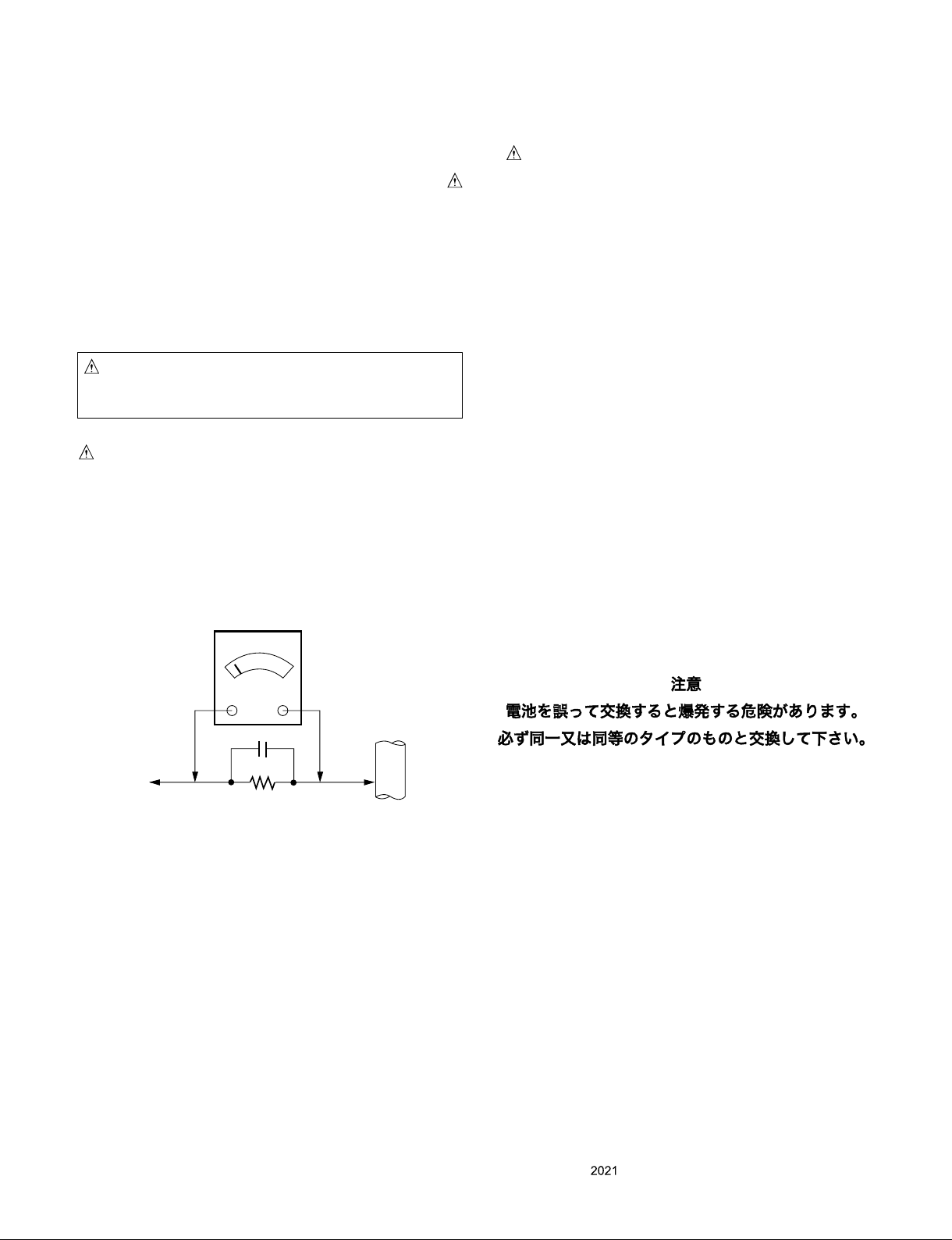
c. Connecting a test substitute in parallel with an electrolytic
capacitor in the receiver.
explosion hazard.
correctly installed.
7. Always connect the test receiver ground lead to the receiver
lead.
unit under test.
devices.
installed.
SERVICING PRECAUTIONS

- 5 - Copyright © LG Electronics Inc. All rights reserved.
Only training and service purposes.
IC Remove/Replacement
Some chassis circuit boards have slotted holes (oblong) through
which the IC leads are inserted and then bent flat against the
circuit foil. When holes are the slotted type, the following technique
should be used to remove and replace the IC. When working with
boards using the familiar round hole, use the standard technique
as outlined in paragraphs 5 and 6 above.
Removal
1. Desolder and straighten each IC lead in one operation by gently
prying up on the lead with the soldering iron tip as the solder
melts.
2. Draw away the melted solder with an anti-static suction-type
solder removal device (or with solder braid) before removing the
IC.
Replacement
1. Carefully insert the replacement IC in the circuit board.
2. Carefully bend each IC lead against the circuit foil pad and
solder it.
3. Clean the soldered areas with a small wire-bristle brush.
(It is not necessary to reapply acrylic coating to the areas).
"Small-Signal" Discrete Transistor
Removal/Replacement
1. Remove the defective transistor by clipping its leads as close as
possible to the component body.
2. Bend into a "U" shape the end of each of three leads remaining
on the circuit board.
3. Bend into a "U" shape the replacement transistor leads.
4. Connect the replacement transistor leads to the corresponding
leads extending from the circuit board and crimp the "U" with
long nose pliers to insure metal to metal contact then solder
each connection.
Power Output, Transistor Device
Removal/Replacement
1. Heat and remove all solder from around the transistor leads.
2. Remove the heat sink mounting screw (if so equipped).
3. Carefully remove the transistor from the heat sink of the circuit
board.
4. Insert new transistor in the circuit board.
5. Solder each transistor lead, and clip off excess lead.
6. Replace heat sink.
Diode Removal/Replacement
1. Remove defective diode by clipping its leads as close as
possible to diode body.
2. Bend the two remaining leads perpendicular y to the circuit
board.
3. Observing diode polarity, wrap each lead of the new diode
around the corresponding lead on the circuit board.
4. Securely crimp each connection and solder it.
5. Inspect (on the circuit board copper side) the solder joints of
the two "original" leads. If they are not shiny, reheat them and if
necessary, apply additional solder.
Fuse and Conventional Resistor
Removal/Replacement
1. Clip each fuse or resistor lead at top of the circuit board hollow
stake.
2. Securely crimp the leads of replacement component around
notch at stake top.
3. Solder the connections.
CAUTION: Maintain original spacing between the replaced
component and adjacent components and the circuit board to
prevent excessive component temperatures.
Circuit Board Foil Repair
Excessive heat applied to the copper foil of any printed circuit
board will weaken the adhesive that bonds the foil to the circuit
board causing the foil to separate from or "lift-off" the board. The
following guidelines and procedures should be followed whenever
this condition is encountered.
At IC Connections
To repair a defective copper pattern at IC connections use the
following procedure to install a jumper wire on the copper pattern
side of the circuit board. (Use this technique only on IC
connections).
1. Carefully remove the damaged copper pattern with a sharp
knife. (Remove only as much copper as absolutely necessary).
2. carefully scratch away the solder resist and acrylic coating (if
used) from the end of the remaining copper pattern.
3. Bend a small "U" in one end of a small gauge jumper wire and
carefully crimp it around the IC pin. Solder the IC connection.
4. Route the jumper wire along the path of the out-away copper
pattern and let it overlap the previously scraped end of the good
copper pattern. Solder the overlapped area and clip off any
excess jumper wire.
At Other Connections
Use the following technique to repair the defective copper pattern
at connections other than IC Pins. This technique involves the
installation of a jumper wire on the component side of the circuit
board.
1. Remove the defective copper pattern with a sharp knife.
Remove at least 1/4 inch of copper, to ensure that a hazardous
condition will not exist if the jumper wire opens.
2. Trace along the copper pattern from both sides of the pattern
break and locate the nearest component that is directly
connected to the affected copper pattern.
3. Connect insulated 20-gauge jumper wire from the lead of the
nearest component on one side of the pattern break to the lead
of the nearest component on the other side.
Carefully crimp and solder the connections.
CAUTION: Be sure the insulated jumper wire is dressed so the
it does not touch components or sharp edges.

- 6 - Copyright © LG Electronics Inc. All rights reserved.
Only training and service purposes.
SPECIFICATION
1. Application range
2. General Specication
1 Input
-
tion
-
tion
- RGB444
IR Receiver O
Brightness sensor O
O
2 Output
Chain
-
tion
Built-in
-12dB
Audio Out Output type
Output level
Optical Audio out O

- 7 - Copyright © LG Electronics Inc. All rights reserved.
Only training and service purposes.
3-
cial
Fea-
Board-in
-
sor
Board-in
-
able
none
4
signal
Operating
5 LG Code
6
7
8 ± 3sec during 24 hours
sec
11
12 Environ-
Condition
Operation
deg
Operation
deg
5
13 Absolute
rating
Current

- 8 - Copyright © LG Electronics Inc. All rights reserved.
Only training and service purposes.
Fre-
Cycle
-
play
Front
Resolution
1 128 88 All inputs
628 1 4 23
2 - 65 48.363 1344 24 136
- 768 3 6
3 74.5 44.772 1664 64 128
748 3 5
4 - 85.86 47.7 1366 72 144 216 1366 x 768
- 768 1 3 23
5 1688 48 112 248
1 3 38
6 - 146.25 176
3 6
7 148.5 67.5 88 44 88
1125 4 5 46
8 67.5 176 88
8 72
3. Signal Timing (Supporting Resolution)
3.1. HDMI/DP (PC Mode)
3.2. HDMI/DP (DTV Mode)
Resolution
1 31.5 O
2 31.25 O
3 37.5 O
4 45 O
5 28.1 O
6 33.75 O
7 56.25 O
8 67.432 O
67.5 O
67.5 O

Copyright © LG Electronics Inc. All rights reserved.
Only training and service purposes.
BLOCK DIAGRAM
1. Main Board(M16PP board)
LAEC015-GN
USB 2.0
M16++
HDMI2
DP
RX1
RX2
HDMI1
HDMI Switch IC
TxA
TxB
MICOM
(TI)
I2C I2C
DTA2010, EYE Sensor
FPGA(Arria 5)
Temp Sensor
NVRAM (1Mb)
UTP
IR/Brightness
Sensor
IR
eMMC
EYE_SDA/SCL
Wafer 51P
DDR3 ×2
Vby1
FHD
eMMC
M0
M1
I2C
I2C
PHY
I2C
I2S/AUDIO
USB 2.0
USB 2.0
8GB
Rx3
Rx2
Rx1
DP_Rx0
1,920 x 1,080 60P
TX DP
I2C
Level
Shift
+5V +3.3V
EEPROM_VCC
EEPROM_P/U
RTC
PCF8523
EEPROM
32Kb
HDMI3
Audio In
MAX3232
RS-232C IN
RS-232C OUT
R1IN ROUT1
DOUT1 DIN1
R2IN
DOUT2 DIN2
ROUT2
M1
M4
M4
M1
SN74LV
UART_TX
UART_RX
MICOM
SEL[1:0]
SEL[1:0] Connection Connection
Clone
DDR4 ×2
SPDIF OUT
SPDIF
DC
ON/OFF
Audio
AMP
SPK (External)
`18W (9W x2EA)
8Key
Power.Set, <, >
Up, Down, Menu, Input
802.11ac
Power controller
Board(LH)
SPI

Copyright © LG Electronics Inc. All rights reserved.
Only training and service purposes.
2. FPGA board(Arria5)
FPGA IC
DDR3(4Gbit) X 2EA
DDR3(4Gbit) X 2EA
512 Mbit
(QSPI)
Ethernet PHY
(x 4EA)
Ethernet PHY
(x 4EA)
LAN X 4EA
LAN X 4EA
Vx1 In
Vx1 60Hz
J-TAG
(JTAG DEBUG 8P)
TCK/TDI/TMS/TDO
LAN_RESET
M16++
I2C BANK 7A
FPGA_RESET
QSPI Update
Wafer
(27Mhz)
(50 Mhz)
4EA
(25Mhz)
BANK 4A
BANK 8D
4EA
(25Mhz)
MDIO0
MDC0
#0/3_GTXCLK
#0/3_TXD0~3
#0/3_PHY_INT
#0/3_TXEN
BANK 3A
FPPDATA1/2/3/4
TCK/TDI/TMS/TDO
#0/3_MDI0/4_P/N
#0/3_LED_LINK/ACT
BANK 7B
#0/3_RXCLK
#0/3_RXD0/3
+3.3V_NORMAL
#0/3_ETH_PHYRSTB
Control Jack
I2C / GPIO
HTPDN_o
LOCKn_OUT
+3.3V_NORMAL
FPGA_rst_n_#1ST (In)
Vx1 Clock Out
Vx1 Rx
+3.3V_NORMAL
Rx_rst_n(Vx1)
+3.3V_NORMAL
Tx_rst_n(Vx1)
Vx1 Tx

Copyright © LG Electronics Inc. All rights reserved.
Only training and service purposes.
120
450
540
470 460
545
570
510
480
220
210
200
EXPLODED VIEW
Many electrical and mechanical parts in this chassis have special safety-related characteristics. These
parts are identified by in the EXPLODED VIEW.
It is essential that these special safety parts should be replaced with the same components as
recommended in this manual to prevent Shock, Fire, or other Hazards.
Do not modify the original design without permission of manufacturer.
IMPORTANT SAFETY NOTICE

No. Picture
110
111
112
113
114
115
120
170
180
190
200
210
220
230
240
250
260
270
280
290
300
310
320
330
340
350
360
370
380
390
400
410
420

No. Picture
430
440
450
460
470
480
490
510
540
545
570
610
620
630
640
650
660
AC6
AR1
HR1
HR2
HR3
HS1
HS2
HS3
HW1

DISASSEMBLY
Copyright ⓒ2021 LG Electronics Inc. All rights reserved.
Only training and service purposes.

1. Disassemble Step
■Dismount LED Display Module
LED Display Module
Step1. Power off the LED display.
Step2. Hold the 2pcs handles, push the lock inward and pull the handles toward outside, and then take it up.
Step3. Take the tool up and horizontally fit it closely to the display surface. Please pay more attention to the direction.
Step4. Pull the handles towards the center.
Copyright ⓒ2021 LG Electronics Inc. All rights reserved.
Only training and service purposes.

1. Disassemble Step
■Dismount LED Display Module
LED Display Module
Step4. Pull the handles towards the center.
Step5. Ensure the magnet is locked. Take down the LDM carefully.
Step6. Put down the LDM and tool together carefully onto an anti-static soft pad.
(such as white foam which used to protect the parts in the flight case)
Step7. Push the lock toward inside and pull the handles toward outside and lift the tool up carefully.
Copyright ⓒ2021 LG Electronics Inc. All rights reserved.
Only training and service purposes.

1. Disassemble Step
■SET Disassemble
SET Disassemble
Step1. All the LMDs (LED Panel) have labels stuck on the back side. Please remove all LDMs by paying attention to their numbers.
Step2. Disconnect the sensor box module and the connected cable.
Copyright ⓒ2021 LG Electronics Inc. All rights reserved.
Only training and service purposes.

1. Disassemble Step
■SET Disassemble
SET Disassemble
Step3. Uninstall Screws
Uninstall 11 pcs fasten Uninstall 16 pcs M4 flat head screws
Copyright ⓒ2021 LG Electronics Inc. All rights reserved.
Only training and service purposes.

1. Disassemble Step
■SET Disassemble
SET Disassemble
Step4. Uninstall M4 Screws
Copyright ⓒ2021 LG Electronics Inc. All rights reserved.
Only training and service purposes.

1. Disassemble Step
■SET Disassemble
SET Disassemble
Step5. Unfasten with a hexagonal plate.
Copyright ⓒ2021 LG Electronics Inc. All rights reserved.
Only training and service purposes.
This manual suits for next models
1
Table of contents
Other LG Digital Signage manuals
Popular Digital Signage manuals by other brands

Space Pole
Space Pole SPK200 installation guide

EYEZONE
EYEZONE B1080PX Series user manual

Kintec Digital Technology
Kintec Digital Technology KDS‐0702 operating instructions

IBASE Technology
IBASE Technology SI-60E-M user manual

Advanced Kiosks
Advanced Kiosks Outdoor Monolith owner's manual

peerless-AV
peerless-AV KIP540B manual