1. List of functions
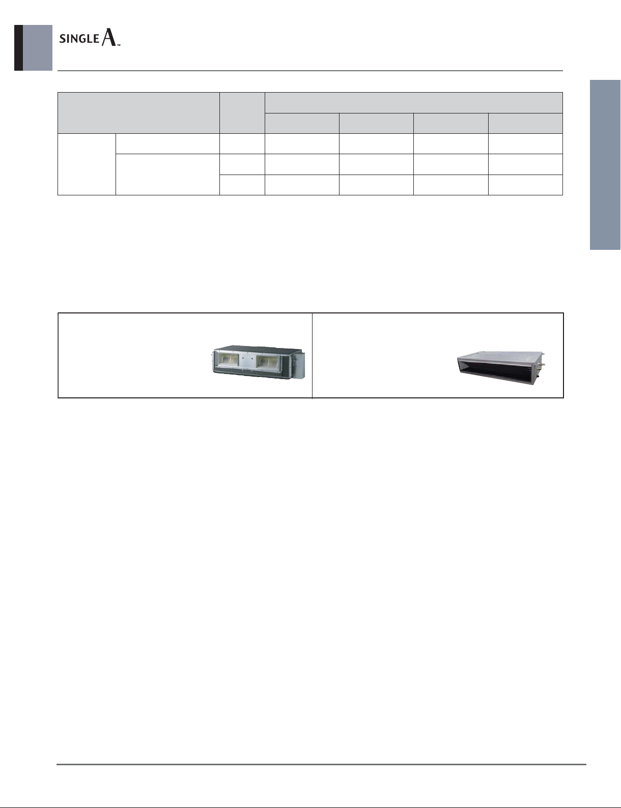
Ceiling concealed duct - Middle static pressure
_ 1
Indoor Units
Note
1. * : These functions need to connect the wired remote controller.
2. ** : It is included by default when the product is manufactured.
3. For synchro operation, some functions and accessories are not
available. Check the outdoor unit’s PDB.
O : Applied X : Not applied
Accessory model name : Installed at field, ordered and purchased
separately by the corresponding model name, supplied with sepa-
rate package
Category Functions
ABNW18GBHC0 [UB18C NH0]
ABNW24GBHC0 [UB24C NH0]
Air flow
Air purifying
Installation
Reliability
Convenience
Individual
control
Network
Solution
Special
function kit
Others
2
X
X
X
X
3 / 3 / 3
X
X / X
X
X
X
X
O
ABDPG
O
X
X
X
O
O
O
X
X
O
O
X
O
O
O
O
O
PQRCVSL0/PQRCVSL0QW/PREMTB001/PREMTBB01
X
PQRCVCL0Q / PQRCVCL0QW**
X
PQWRHQ0FDB
X
O
PQDSA / PDRYCB000
PDRYCB400
PDRYCB300
X
ABZCA
X
X
X
X
X
PQRSTA0
PZCWRCG3
Air supply outlet
Airflow direction control (left & right)
Airflow direction control (up & down)
Auto swing (left & right)
Auto swing (up & down)
Airflow steps (fan/cool/heat)
Chaos wind(auto wind)
Jet cool/heat
Swirl wind*
Triple filter (Deodorizing)
Plasma air purifier
Allergy Safe filter
Long-life prefilter (washable / anti-fungus)
Drain pump
E.S.P. control*
Electric heater
High ceiling operation*
Auto Elevation Grille
Hot start
Self diagnosis
Auto changeover
Auto cleaning
Auto operation(artificial intelligence)
Auto Restart
Child lock*
Forced operation
Group control*
Sleep mode
Timer(on/off)
Timer(weekly)*
Two thermistor control*
Wired remote controller
Premium wired remote controller
Simple wired remote controller
Simple Wired remote controller(for hotel use)
Wireless remote controller*
General central controller (Non LGAP)
Network Solution(LGAP)
Simple Dry contact (outside AC 220V power source)
2 Points Dry Contact (For setback)
Dry contact for Thermostat
PI 485(for Indoor Unit)
Zone controller
CTI(Communication transfer interface)
Electronic thermostat
Telecom shelter controller
Independent Power Module
CO2Sensor
Remote temperature sensor
Group control wire


![LG LZ-H080GBA2 [ARVU053ZEA2] Installation and operation manual](/data/manuals/w3/a/w3a1/sources/lg-arvu053zea2-manual.jpg "LG LZ-H080GBA2 [ARVU053ZEA2] Installation and operation manual")