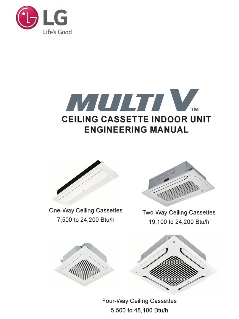
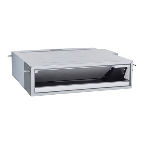
LG MULTI V ARNU073TAA4 User manual

CEILING CASSETTE INDOOR UNIT
INSTALLATION MANUAL
One-Way Models
• ARNU073TUD4
• ARNU093TUD4
• ARNU123TUD4
• ARNU183TTD4
• ARNU243TTD4
Four-Way 2'x 2'Models
• ARNU053TRD4
• ARNU073TRD4
• ARNU093TRD4
• ARNU123TRD4
• ARNU153TQD4
• ARNU183TQD4
Two-Way Models
• ARNU183TSA4
• ARNU243TSA4
Four-Way 3'x 3'Models
• ARNU073TAA4
• ARNU093TAA4
• ARNU123TAA4
• ARNU153TAA4
• ARNU183TAA4
• ARNU243TAA4
• ARNU283TAA4
• ARNU363TAA4
• ARNU423TAA4
• ARNU483TAA4

For continual product development, LG Electronics U.S.A., Inc. reserves the right to change specifications without notice.
© LG Electronics U.S.A., Inc.
PROPRIETARY DATA NOTICE
For more technical materials such as submittals, catalogs, engineering,
installation, best practices, and owner’s manuals, visit www.lghvac.com.
Do not throw away, destroy, or lose this manual.
Please read carefully and store in a safe place for future reference.
Content familiarity is required for proper installation.
The instructions included in this manual must be followed to prevent product malfunction, property damage, injury, or death to the user or
other people. Incorrect operation due to ignoring any instructions will cause harm or damage. The level of seriousness is classified by the
symbols described by the summary list of safety precautions on page 4.
This document, as well as all reports, illustrations, data, information,
and other materials are the property of LG Electronics U.S.A., Inc., and are
disclosed by LG Electronics U.S.A., Inc. only in confidence.

3
Installation Manual
Due to our policy of continuous product innovation, some specifications may change without notification.
©LG Electronics U.S.A., Inc., Englewood Cliffs, NJ. All rights reserved. “LG” is a registered trademark of LG Corp.
TABLE OF CONTENTS
Safety Instructions ...................................................................................................................................................................................................... 4-7
Unit Nomenclature...........................................................................................................................................................................................................8
Introduction.................................................................................................................................................................................................................9-11
General Data ............................................................................................................................................................................................................ 12-26
6SHFL¿FDWLRQV ........................................................................................................................................................................................................ 12-17
(OHFWULFDO'DWD .............................................................................................................................................................................................................18
'LPHQVLRQV........................................................................................................................................................................................................... 19-24-
5HIULJHUDQW3LSLQJ'LDJUDPV ................................................................................................................................................................................. 25-26
General Installation Guidelines.............................................................................................................................................................................. 27-33
/RFDWLRQ6HOHFWLRQ ................................................................................................................................................................................................. 27-28
5HTXLUHG&OHDUDQFHV...................................................................................................................................................................................................28
8QSDFNDQG,QVSHFW.....................................................................................................................................................................................................29
,QVWDOO&DVVHWWH)UDPH........................................................................................................................................................................................... 30-33
Refrigerant Piping ................................................................................................................................................................................................... 33-38
3LSLQJ0DWHULDOVDQG+DQGOLQJ.....................................................................................................................................................................................33
3LSH6XSSRUWV............................................................................................................................................................................................................ 34-
3LSLQJ3UHSDUDWLRQ................................................................................................................................................................................................. 35-37
3LSH&RQQHFWLRQV,QVXODWLQJWKH5HIULJHUDQW3LSLQJ ..................................................................................................................................................38
General Condensate Piping.................................................................................................................................................................................... 39-40
Install Decorative Cover.......................................................................................................................................................................................... 41-43
Install Branch Duct.................................................................................................................................................................................................. 44-46
Wiring ....................................................................................................................................................................................................................... 47-66
*HQHUDO,QIRUPDWLRQ6HSDUDWLQJ:LULQJDQG&DEOHV ..................................................................................................................................................47
3RZHU:LULQJ&RPPXQLFDWLRQ&DEOH&RQQHFWLRQV....................................................................................................................................................48
3RZHU6XSSO\3RZHU:LULQJ6SHFL¿FDWLRQV...............................................................................................................................................................49
&RPPXQLFDWLRQV&DEOH6SHFL¿FDWLRQV .................................................................................................................................................................. 50-52
&RQQHFWLRQ3URFHGXUH........................................................................................................................................................................................... 53-54
2QH:D\7778)UDPHV....................................................................................................................................................................................... 55-57
7ZR:D\76)UDPH............................................................................................................................................................................................... 58-60
)RXU:D\&DVVHWWH)UDPHV................................................................................................................................................................................... 61-65
)RXU:D\7574)UDPHV ................................................................................................................................................................................. 62-63
)RXU:D\7$)UDPHV......................................................................................................................................................................................... 64-65
&RQWUROOHUDQG2SW:DOO0RXQWHG6HQVRU,QVWDOODWLRQ.................................................................................................................................................66
Controls Setup......................................................................................................................................................................................................... 67-72
Installation Checklist............................................................................................................................................................................................... 73-74

4
MULTI V Ceiling Cassette Indoor Units
Due to our policy of continuous product innovation, some specifications may change without notification.
©LG Electronics U.S.A., Inc., Englewood Cliffs, NJ. All rights reserved. “LG” is a registered trademark of LG Corp.
The instructions below must be followed to prevent product malfunction, property damage, injury or death to the user or other people. Incor-
rect operation due to ignoring any instructions will cause harm or damage. The level of seriousness is classified by the symbols below.
SAFETY INSTRUCTIONS
WARNING
Do not install or remove the unit by yourself (customer).
Ask the dealer or an authorized technician to install the unit.
,PSURSHULQVWDOODWLRQE\WKHXVHUPD\UHVXOWLQZDWHUOHDNDJH¿UH
H[SORVLRQHOHFWULFVKRFNSK\VLFDOLQMXU\RUGHDWK
For replacement of an installed unit, always contact an
authorized LG service provider.
7KHUHLVULVNRI¿UHHOHFWULFVKRFNH[SORVLRQDQGSK\VLFDOLQMXU\RU
GHDWK
The outdoor unit is shipped with refrigerant and the service
valves closed. Do not open service valves on the unit
until all non-condensables have been removed from the
piping system and authorization has been obtained from the
commissioning agent.
7KHUHLVDULVNRISK\VLFDOLQMXU\RUGHDWK
Do not run the compressor with the service valves
closed.
7KHUHLVULVNRIH[SORVLRQSK\VLFDOLQMXU\RUGHDWK
Periodically check that the outdoor unit is not damaged.
7KHUHLVULVNRIH[SORVLRQSK\VLFDOLQMXU\RUGHDWK
Replace all control box and panel covers.
,IFRYHUSDQHOVDUHQRWLQVWDOOHGVHFXUHO\GXVWZDWHUDQGDQLPDOVPD\
HQWHUWKHXQLWFDXVLQJ¿UHHOHFWULFVKRFNDQGSK\VLFDOLQMXU\RUGHDWK
Always check for system refrigerant leaks after the unit has
been installed or serviced.
([SRVXUHWRKLJKFRQFHQWUDWLRQOHYHOVRIUHIULJHUDQWJDVPD\OHDGWR
LOOQHVVRUGHDWK
Do not install the unit using defective hanging, attaching,
or mounting hardware.
7KHUHLVULVNRISK\VLFDOLQMXU\RUGHDWK
Wear protective gloves when handling equipment.
6KDUSHGJHVPD\FDXVHSHUVRQDOLQMXU\
Dispose the packing materials safely.
• 3DFNLQJPDWHULDOVVXFKDVQDLOVDQGRWKHUPHWDORUZRRGHQSDUWV
PD\FDXVHSXQFWXUHZRXQGVRURWKHULQMXULHV
• 7HDUDSDUWDQGWKURZDZD\SODVWLFSDFNDJLQJEDJVVRWKDWFKLOGUHQ
PD\QRWSOD\ZLWKWKHPDQGULVNVXIIRFDWLRQDQGGHDWK
'RQRWLQVWDOOWKHXQLWLQDQ\ORFDWLRQH[SRVHGWRRSHQÀDPH
or extreme heat. Do not touch the unit with wet hands.
7KHUHLVULVNRI¿UHHOHFWULFVKRFNH[SORVLRQDQGSK\VLFDOLQMXU\RUGHDWK
Install the unit considering the potential for earthquakes.
,PSURSHULQVWDOODWLRQPD\FDXVHWKHXQLWWRIDOOUHVXOWLQJLQSK\VLFDO
LQMXU\RUGHDWK
Do not change the settings of the protection devices.
,IWKHSUHVVXUHVZLWFKWKHUPDOVZLWFKRURWKHUSURWHFWLRQGHYLFHLV
VKRUWHGDQGIRUFHGWRRSHUDWHLPSURSHUO\RUSDUWVRWKHUWKDQWKRVH
VSHFL¿HGE\/*DUHXVHGWKHUHLVULVNRI¿UHHOHFWULFVKRFNH[SORVLRQ
DQGSK\VLFDOLQMXU\RUGHDWK
If the air conditioner is installed in a small space, take mea-
sures to prevent the refrigerant concentration from exceed-
ing safety limits in the event of a refrigerant leak.
&RQVXOWWKHODWHVWHGLWLRQRI$6+5$($PHULFDQ6RFLHW\RI+HDWLQJ
5HIULJHUDWLQJDQG$LU&RQGLWLRQLQJ(QJLQHHUV6WDQGDUG,IWKHUH-
IULJHUDQWOHDNVDQGVDIHW\OLPLWVDUHH[FHHGHGLWFRXOGUHVXOWLQSHUVRQDO
LQMXULHVRUGHDWKIURPR[\JHQGHSOHWLRQ
INSTALLATION
DANGER
'RQRWXVHRUVWRUHÀDPPDEOHJDVRUFRPEXVWLEOHVQHDUWKHXQLW
7KHUHLVULVNRISURGXFWIDLOXUH¿UHH[SORVLRQDQGSK\VLFDOLQMXU\RUGHDWK
TABLE OF SYMBOLS
DANGER 7KLVV\PEROLQGLFDWHVDQLPPLQHQWO\KD]DUGRXVVLWXDWLRQZKLFKLIQRWDYRLGHGZLOOUHVXOWLQGHDWKRUVHULRXVLQMXU\
WARNING 7KLVV\PEROLQGLFDWHVDSRWHQWLDOO\KD]DUGRXVVLWXDWLRQZKLFKLIQRWDYRLGHGFRXOGUHVXOWLQGHDWKRUVHULRXVLQMXU\
CAUTION 7KLVV\PEROLQGLFDWHVDSRWHQWLDOO\KD]DUGRXVVLWXDWLRQZKLFKLIQRWDYRLGHGPD\UHVXOWLQPLQRURUPRGHUDWHLQMXU\
7KLVV\PEROLQGLFDWHVVLWXDWLRQVWKDWPD\UHVXOWLQHTXLSPHQWRUSURSHUW\GDPDJHDFFLGHQWVRQO\
7KLVV\PEROLQGLFDWHVDQDFWLRQWKDWVKRXOGQRWEHSHUIRUPHG

5
Installation Manual
Due to our policy of continuous product innovation, some specifications may change without notification.
©LG Electronics U.S.A., Inc., Englewood Cliffs, NJ. All rights reserved. “LG” is a registered trademark of LG Corp.
SAFETY INSTRUCTIONS
INSTALLATION – CONTINUED
Properly insulate all cold surfaces to prevent “sweating.”
&ROGVXUIDFHVVXFKDVXQLQVXODWHGSLSHFDQJHQHUDWHFRQGHQVDWHWKDW
PD\GULSDQGFDXVHDVOLSSHU\ÀRRUFRQGLWLRQDQGRUZDWHUGDPDJHWR
ZDOOV
When installing the unit in a hospital, mechanical room, or
VLPLODUHOHFWURPDJQHWLF¿HOG(0)VHQVLWLYHHQYLURQPHQW
SURYLGHVXႈFLHQWSURWHFWLRQDJDLQVWHOHFWULFDOQRLVH
,QYHUWHUHTXLSPHQWSRZHUJHQHUDWRUVKLJKIUHTXHQF\PHGLFDOHTXLS
PHQWRUUDGLRFRPPXQLFDWLRQHTXLSPHQWPD\FDXVHWKHDLUFRQGLWLRQHU
WRRSHUDWHLPSURSHUO\7KHXQLWPD\DOVRDIIHFWVXFKHTXLSPHQWE\FUHDW-
LQJHOHFWULFDOQRLVHWKDWGLVWXUEVPHGLFDOWUHDWPHQWRULPDJHEURDGFDVW-
LQJ
Do not use the product for special purposes such as pre-
serving foods, works of art, wine coolers, or other precision
air conditioning applications. This equipment is designed to
provide comfort cooling and heating.
7KHUHLVULVNRISURSHUW\GDPDJH
Do not make refrigerant substitutions. Use R410A only.
,IDGLIIHUHQWUHIULJHUDQWLVXVHGRUDLUPL[HVZLWKRULJLQDOUHIULJHUDQWWKH
XQLWZLOOPDOIXQFWLRQDQGEHGDPDJHG
Do not install the unit in a noise sensitive area.
When connecting refrigerant tubing, remember to allow for
pipe expansion.
,PSURSHUSLSLQJPD\FDXVHUHIULJHUDQWOHDNVDQGV\VWHPPDOIXQFWLRQ
Take appropriate actions at the end of HVAC equipment life
to recover, recycle, reclaim or destroy R410A refrigerant ac-
cording to applicable U.S. Environmental Protection Agency
(EPA) rules.
Periodically check that the outdoor unit is not damaged.
7KHUHLVDULVNRIHTXLSPHQWGDPDJH
Install the unit in a safe location where no one can step on or
fall onto it. Do not install the unit with defective hanging,
attaching, or mounting hardware.
7KHUHLVULVNRIXQLWDQGSURSHUW\GDPDJH
Install the drain hose to ensure adequate drainage.
7KHUHLVDULVNRIZDWHUOHDNDJHDQGSURSHUW\GDPDJH
'RQRWVWRUHRUXVHÀDPPDEOHJDVFRPEXVWLEOHVQHDUWKH
unit.
7KHUHLVULVNRISURGXFWIDLOXUH
Always check for system refrigerant leaks after the unit has
been installed or serviced.
/RZUHIULJHUDQWOHYHOVPD\FDXVHSURGXFWIDLOXUH
The outdoor unit is shipped with refrigerant and the service
valves closed. Do not open service valves on the unit un-
til all non-condensables have been removed from the piping
system and authorization to do so has been obtained from
the commissioning agent.
7KHUHLVDULVNRIUHIULJHUDQWFRQWDPLQDWLRQUHIULJHUDQWORVVDQGHTXLS
PHQWGDPDJH
CAUTION
Be very careful when transporting the product.
• 'RQRWDWWHPSWWRFDUU\WKHSURGXFWZLWKRXWDVVLVWDQFH
• 6RPHSURGXFWVXVHSRO\SURS\OHQHEDQGVIRUSDFNDJLQJ 'RQRWXVHSRO\SURS\OHQHEDQGVWROLIWWKHXQLW
• 6XVSHQGWKHXQLWIURPWKHEDVHDWVSHFLILHGSRVLWLRQV
• 6XSSRUWWKHXQLWDPLQLPXPRIIRXUSRLQWVWRDYRLGVOLSSDJHIURPULJJLQJDSSDUDWXV

6
MULTI V Ceiling Cassette Indoor Units
Due to our policy of continuous product innovation, some specifications may change without notification.
©LG Electronics U.S.A., Inc., Englewood Cliffs, NJ. All rights reserved. “LG” is a registered trademark of LG Corp.
SAFETY INSTRUCTIONS
WIRING
DANGER
High voltage electricity is required to operate this system.
Adhere to the National Electrical Codes and these
instructions when wiring.
,PSURSHUFRQQHFWLRQVDQGLQDGHTXDWHJURXQGLQJFDQFDXVHDFFLGHQWDO
LQMXU\RUGHDWK
Always ground the unit following local, state, and National
Electrical Codes.
7XUQWKHSRZHURႇDWWKHQHDUHVWGLVFRQQHFWEHIRUHVHUYLFLQJ
the equipment.
(OHFWULFVKRFNFDQFDXVHSK\VLFDOLQMXU\RUGHDWK
Properly size all circuit breakers or fuses.
WARNING
The information contained in this manual is intended for use
E\DQLQGXVWU\TXDOL¿HGH[SHULHQFHGFHUWL¿HGHOHFWULFLDQ
familiar with the U.S. National Electric Code (NEC) who is
equipped with the proper tools and test instruments.
)DLOXUHWRFDUHIXOO\UHDGDQGIROORZDOOLQVWUXFWLRQVLQWKLVPDQXDOFDQ
UHVXOWLQHTXLSPHQWPDOIXQFWLRQSURSHUW\GDPDJHSHUVRQDOLQMXU\RU
GHDWK
Ensure the unit is connected to a dedicated power source
that provides adequate power.
,IWKHSRZHUVRXUFHFDSDFLW\LVLQDGHTXDWHRUWKHHOHFWULFZRUNLVQRW
SHUIRUPHGSURSHUO\LWPD\UHVXOWLQ¿UHHOHFWULFVKRFNSK\VLFDOLQMXU\RU
GHDWK
Refer to local, state, and federal codes, and use power wires
RIVXႈFLHQWFXUUHQWFDSDFLW\DQGUDWLQJ
:LUHVWKDWDUHWRRVPDOOPD\JHQHUDWHKHDWDQGFDXVHD¿UH
6HFXUHDOO¿HOGZLULQJFRQQHFWLRQVZLWKDSSURSULDWHZLUH
strain relief.
,PSURSHUO\VHFXULQJZLUHVZLOOFUHDWHXQGXHVWUHVVRQHTXLSPHQWSRZHU
OXJV,QDGHTXDWHFRQQHFWLRQVPD\JHQHUDWHKHDWFDXVHD¿UHDQG
SK\VLFDOLQMXU\RUGHDWK
Properly tighten all power connections.
/RRVHZLULQJPD\RYHUKHDWDWFRQQHFWLRQSRLQWVFDXVLQJD¿UHSK\VLFDO
LQMXU\RUGHDWK
Do not cut, lengthen or shorten the communications and power cable between any dry contact unit and its connected indoor
unit. Do not install the unit in a location where the communications and power cable cannot be safely and easily connected
between the two units. Do not allow strain on this cable.
3RRUFDEOHFRQQHFWLRQVFDQFDXVHHTXLSPHQWPDOIXQFWLRQ

7
Installation Manual
Due to our policy of continuous product innovation, some specifications may change without notification.
©LG Electronics U.S.A., Inc., Englewood Cliffs, NJ. All rights reserved. “LG” is a registered trademark of LG Corp.
OPERATION
DANGER
'RQRWSURYLGHSRZHUWRRURSHUDWHWKHXQLWLILWLVÀRRGHG
or submerged.
7KHUHLVULVNRI¿UHHOHFWULFVKRFNSK\VLFDOLQMXU\RUGHDWK
Use a dedicated power source for this product.
7KHUHLVULVNRI¿UHHOHFWULFVKRFNSK\VLFDOLQMXU\RUGHDWK
Do not operate the disconnect switch with wet hands.
7KHUHLVULVNRI¿UHHOHFWULFVKRFNSK\VLFDOLQMXU\RUGHDWK
Periodically verify the hanging bolts and other hardware
securing the unit have not deteriorated.
,IWKHXQLWIDOOVIURPLWVLQVWDOOHGORFDWLRQLWFDQFDXVHSURSHUW\GDPDJH
SURGXFWIDLOXUHSK\VLFDOLQMXU\RUGHDWK
If refrigerant gas leaks out, ventilate the area before operat-
ing the unit.
,IWKHXQLWLVPRXQWHGLQDQHQFORVHGORZO\LQJRUSRRUO\YHQWLODWHGDUHD
DQGWKHV\VWHPGHYHORSVDUHIULJHUDQWOHDNLWPD\FDXVH¿UHHOHFWULF
VKRFNH[SORVLRQSK\VLFDOLQMXU\RUGHDWK
SAFETY INSTRUCTIONS
&OHDQXSWKHVLWHDIWHULQVWDOODWLRQLV¿QLVKHGDQGFKHFN
that no metal scraps, screws, or bits of wiring have been left
inside or surrounding the unit.
Do not use this equipment in mission critical or special-
purpose applications such as preserving foods, works of art,
wine coolers or refrigeration. This equipment is designed to
provide comfort cooling and heating.
Provide power to the compressor crankcase heaters at least
six (6) hours before operation begins.
6WDUWLQJRSHUDWLRQZLWKDFROGFRPSUHVVRUVXPSVPD\UHVXOWLQVHYHUH
EHDULQJGDPDJHWRWKHFRPSUHVVRUV.HHSWKHSRZHUVZLWFKRQGXULQJ
WKHRSHUDWLRQDOVHDVRQ
Do not block the inlet or outlet.
8QLWPD\PDOIXQFWLRQ
Securely attach the electrical cover to the indoor unit. Non-
VHFXUHGFRYHUVFDQUHVXOWLQ¿UHGXHWRGXVWRUZDWHULQWKH
service panel.
Periodically verify the equipment mounts have not deterio-
rated.
,IWKHEDVHFROODSVHVWKHXQLWFRXOGIDOODQGFDXVHSURSHUW\GDPDJHRU
SURGXFWIDLOXUH
Do not allow water, dirt, or animals to enter the unit.
7KHUHLVULVNRIXQLWIDLOXUH
WARNING
Do not allow water, dirt, or animals to enter the unit.
7KHUHLVULVNRIXQLWIDLOXUH¿UHHOHFWULFVKRFNSK\VLFDOLQMXU\RUGHDWK
Avoid excessive cooling and periodically perform ventilation
to the unit.
,QDGHTXDWHYHQWLODWLRQLVDKHDOWKKD]DUG
Do not touch the refrigerant piping during or after opera-
tion.
,WFDQFDXVHEXUQVRUIURVWELWH
Do not operate the unit with the panel(s) or protective
FRYHUVUHPRYHGNHHS¿QJHUVDQGFORWKLQJDZD\IURP
moving parts.
7KHURWDWLQJKRWFROGDQGKLJKYROWDJHSDUWVRIWKHXQLWFDQFDXVH
SK\VLFDOLQMXU\RUGHDWK
Periodically check power cable and connection for damage.
&DEOHPXVWEHUHSODFHGE\WKHPDQXIDFWXUHULWVVHUYLFHDJHQWRUVLPLODU
TXDOL¿HGSHUVRQVLQRUGHUWRDYRLGSK\VLFDOLQMXU\DQGRUHOHFWULFVKRFN
Do not open the inlet grille of the unit during operation.
Do not operate the unit with the panels or guards re-
moved. Do not open the inlet grille of the unit during op-
eration. Do not insert hands or other objects through the
inlet or outlet when the unit is powered. Do not touch the
HOHFWURVWDWLF¿OWHULIWKHXQLWLQFOXGHVRQH7KHXQLWFRQWDLQV
sharp, rotating, hot, and high voltage parts that can cause
SHUVRQDOLQMXU\DQGRUHOHFWULFVKRFN
7KHXQLWFRQWDLQVVKDUSURWDWLQJKRWDQGKLJKYROWDJHSDUWVWKDWFDQ
FDXVHSHUVRQDOLQMXU\DQGRUHOHFWULFVKRFN
Ensure no power is connected to the unit other than as
directed in this manual. Remove power from the unit before
removing or servicing the unit.
7KHUHLVULVNRIXQLWIDLOXUH¿UHHOHFWULFVKRFNSK\VLFDOLQMXU\RUGHDWK
Securely attach the electrical cover to the unit.
1RQVHFXUHGHOHFWULFDOFRYHUVFDQUHVXOWLQEXUQVRUHOHFWULFVKRFNGXHWR
GXVWRUZDWHULQWKHVHUYLFHSDQHO
CAUTION
To avoid physical injury, use caution when cleaning or servicing the air conditioner.

8
MULTI V Ceiling Cassette Indoor Units
Due to our policy of continuous product innovation, some specifications may change without notification.
©LG Electronics U.S.A., Inc., Englewood Cliffs, NJ. All rights reserved. “LG” is a registered trademark of LG Corp.
Cassette Indoor Units Nomenclature
ARN U07 3TA A
Generation
4 = Fourth
TT = 1-Way Ceiling Cassette
TU = 1-Way Ceiling Cassette
TS = 2-Way Ceiling Cassette
TA = 4-Way Ceiling Cassette
TQ = 4-Way Ceiling Cassette
TR = 4-Way Ceiling Cassette
Electrical Ratings
3 = 208–230V/60Hz/1Phase
Nominal Capacity
(Nominal cooling capacity in Btu/h)
Type
U = Inverter Heat Pump
Family
ARN = Multi V Indoor Unit (Refrigerant R410A)
4
Feature
A, C, L, R = Standard
05 = 5,500
07 = 7,500
09 = 9,600
12 = 12,300
15 = 15,400
18 = 19,100
24 = 24,200
28 = 28,000
36 = 36,200
42 = 42,000
48 = 48,000
UNIT NOMENCLATURE
Chassis/Model Type

9
Installation Manual
Due to our policy of continuous product innovation, some specifications may change without notification.
©LG Electronics U.S.A., Inc., Englewood Cliffs, NJ. All rights reserved. “LG” is a registered trademark of LG Corp.
INTRODUCTION
Ceiling Cassette Indoor Units
This manual describes how to install the LG One-Way, Two-Way, and
Four-Way Ceiling Cassette indoor units (IDU) for Multi V Variable
Refrigerant Flow (VRF) heat pump and heat recovery systems. The
table on the next page lists the available models. Refer to LG’s Multi
V Ceiling Cassette Indoor Unit Engineering Manual for complete
detailed engineering data and selection procedures.
Safety
Safety of personnel is the primary concern during all procedures.
Read and understand the safety summary at the front of this manual.
Read and understand this installation procedure before beginning
installation. Use the appropriate tools and accessories during instal-
lation. Plan the work and do not work alone, if possible. Know
how to obtain emergency medical and fire fighting assistance.
Installation Personnel
This equipment is intended for installation by personnel trained
in the required construction, mechanical, electrical, and/or other
disciplines.
• Connecting cable (power and control)
• Pipes - vapor line and liquid line, with insulation
• 3/8" or 1/2" Threaded hanger rods
• 3/8" or 1/2" nuts, flat washers, and lock/split washers
• Insulated drain hose
• Additional drain hose
• Level
• Screwdriver
• Electrical lineman pliers
• Electric drill
• Holesaw
• Drill
• Flaring tool set
• Tubing cutter
• Tube/pipe reamer
• Torque wrenches
• Allen wrench
• Gas-leak detector
• Thermometer
WARNING
,QVWDOODWLRQZRUNPXVWEHSHUIRUPHGE\WUDLQHGSHUVRQQHODQGLQ
DFFRUGDQFHZLWKQDWLRQDOZLULQJVWDQGDUGVDQGDOOQDWLRQDOVWDWHORFDO
RURWKHUDSSOLFDEOHFRGHV,PSURSHULQVWDOODWLRQFDQUHVXOWLQ¿UHHOHFWULF
VKRFNSK\VLFDOLQMXU\RUGHDWK
3OHDVHUHDGLQVWUXFWLRQVEHIRUHLQVWDOOLQJWKLVSURGXFW%HFRPHIDPLOLDU
ZLWKWKHXQLW¶VFRPSRQHQWVDQGFRQQHFWLRQVDQGWKHRUGHURILQVWDOODWLRQ
,QFRUUHFWLQVWDOODWLRQFDQGHJUDGHRUSUHYHQWSURSHURSHUDWLRQ
Figure 1: One-Way TU, TT Frame.
Figure 2: Two-Way TS Frame.
Wired Remote Controller
(Optional)
Air
Intake
Air Outlet
Figure 3: Four-Way TQ, TR Frame.
Wired Remote Controller (Optional)
Filter
Return Air
Supply Air
RemoteController
TEMP
Required Tools (field provided)
Required Parts (field provided)
Air Outlet
Air Intake
Wired Remote Controller
(Optional)
Filter
Figure 4: Four-Way TA Frame.
Air
Intake
Air Outlet
Wired Remote Controller
(Optional)
Air Filter

10
MULTI V Ceiling Cassette Indoor Units
Due to our policy of continuous product innovation, some specifications may change without notification.
©LG Electronics U.S.A., Inc., Englewood Cliffs, NJ. All rights reserved. “LG” is a registered trademark of LG Corp.
Included Parts (Depends on Model)
Part Quantity Image Part Quantity Image
Drain Hose One (1) Cable Ties Four (4)
Metal
Clamp Two (2)
Conduit Bracket
(Appearances
Will Vary
Depending on
Model)
One (1)
Insulation
for Fittings
One (1)
Set
Washers for
Hanging
Bracket
Eight (8)
Paper Pattern
for Installation One (1)
Table 1: Included Items.
For Vapor Piping For Liquid Piping
INTRODUCTION
Table 2: Grille / Panel Accessory Table (Sold Separately).
For Cassette Type Description Model No. Quantity
One-Way Grille Kit for 7 to 12 MBh Indoor Units PT-UUC1
One (1)
Grille Kit for 18 and 24MBh Indoor Units PT-UTC
Two-Way Grille Kit PT-USC
Four-Way (2' x 2') Grille Kit for TR and TQ Frame Indoor Units PT-QCHW0
Four-Way (3' x 3') Standard Panel PT-AAGW0
Premium Panel PT-AFGW0S
)RURWKHUDYDLODEOHDFFHVVRULHVVHHWKH&HLOLQJ&DVVHWWH,QGRRU8QLW(QJLQHHULQJ0DQXDORUWKHDSSOLFDEOHRQHZD\WZRZD\RUIRXUZD\FHLOLQJ
FDVVHWWHVXEPLWWDORQZZZOJKYDFFRP

11
Installation Manual
Due to our policy of continuous product innovation, some specifications may change without notification.
©LG Electronics U.S.A., Inc., Englewood Cliffs, NJ. All rights reserved. “LG” is a registered trademark of LG Corp.
Table 3: Multi V Cassette Indoor Units.
INTRODUCTION
Unit Model Number
Ceiling Cassette One-Way ARNU073TUD4
ARNU093TUD4
ARNU123TUD4
ARNU183TTD4
ARNU243TTD4
Ceiling Cassette: Two-Way
ARNU183TSA4
ARNU243TSA4
Ceiling Cassette: Four-Way (2' x 2')
ARNU053TRD4
ARNU073TRD4
ARNU093TRD4
ARNU123TRD4
ARNU153TQD4
ARNU183TQD4
&HLOLQJ&DVVHWWH)RXU:D\ƍ[ƍ ARNU073TAA4
ARNU093TAA4
ARNU123TAA4
ARNU153TAA4
ARNU183TAA4
ARNU243TAA4
ARNU283TAA4
ARNU363TAA4
ARNU423TAA4
ARNU483TAA4

12
MULTI V Ceiling Cassette Indoor Units
Due to our policy of continuous product innovation, some specifications may change without notification.
©LG Electronics U.S.A., Inc., Englewood Cliffs, NJ. All rights reserved. “LG” is a registered trademark of LG Corp.
R410A Refrigerant
R410A refrigerant has a higher operating pressure in comparison to R22 refrigerant. All piping system materials installed must have a higher
resisting pressure than the materials traditionally used in R22 systems.
R410A refrigerant is an azeotrope of R32 and R125, mixed at 50:50, so the ozone depletion potential (ODP) is 0.
WARNING
'RQRWSODFHWKHUHIULJHUDQWF\OLQGHULQGLUHFWVXQOLJKW5HIULJHUDQWF\OLQGHUZLOOH[SORGHFDXVLQJVHYHUHLQMXU\RUGHDWK
• %HFDXVH5$LVDFRPELQDWLRQRI5DQG5WKHUHTXLUHGDGGLWLRQDOUHIULJHUDQWPXVWEHFKDUJHGLQLWVOLTXLGVWDWH,IWKHUHIULJHUDQWLV
FKDUJHGLQLWVJDVHRXVVWDWHLWVFRPSRVLWLRQFKDQJHVDQGWKHV\VWHPZLOOQRWZRUNSURSHUO\
• 'RQRWKHDWSLSLQJPRUHWKDQQHFHVVDU\GXULQJLQVWDOODWLRQ3LSLQJZLOOEHFRPHVRIWDQGIDLOZKHQSUHVVXUL]HG
• 'RQRWXVHDQ\SLSLQJWKDWKDVQRWEHHQDSSURYHGIRUXVHLQKLJKSUHVVXUHUHIULJHUDQWV\VWHPV3LSLQJZDOOWKLFNQHVVPXVWFRPSO\ZLWK
WKHDSSOLFDEOHORFDOVWDWHDQGIHGHUDOFRGHVIRUWKHSVLGHVLJQSUHVVXUHRI5$,QDGHTXDWHSLSLQJZLOOIDLOZKHQSUHVVXUL]HG
GENERAL DATA

13
Installation Manual
Due to our policy of continuous product innovation, some specifications may change without notification.
©LG Electronics U.S.A., Inc., Englewood Cliffs, NJ. All rights reserved. “LG” is a registered trademark of LG Corp.
Model No. ARNU073TUD4 ARNU093TUD4 ARNU123TUD4 ARNU183TTD4 ARNU243TTD4
Cooling Mode Performance
Capacity (Btu/h) 7,500 9,600 12,300 19,100 24,200
Max. Power Input1(W) 40 40 40 70 70
L/M/H Power Input at Factory Default (W) 16 / 18 / 20 18 / 20 / 22 20 / 22 / 24 24 / 28 / 38 26 / 33 / 51
Heating Mode Performance
Capacity (Btu/h) 8,500 10,900 13,600 21,500 24,200
Max. Power Input1(W) 40 40 40 70 70
L/M/H Power Input at Factory Default (W) 16 / 18 / 20 18 / 20 / 22 20 / 22 / 24 24 / 28 / 38 26 / 33 / 51
Entering Mixed Air
Cooling Max (°F WB) 76 76 76 76 76
Heating Min (°F DB) 59 59 59 59 59
Unit Data
Refrigerant Type2R410A R410A R410A R410A R410A
Refrigerant Control EEV EEV EEV EEV EEV
Sound Pressure3dB(A) (H/M/L) 32 / 29 / 25 35 / 34 / 32 38 / 35 / 32 40 / 37 / 35 43 / 40 / 36
Net Unit Weight (lbs.) 33 33 33 42 42
Shipping Weight (lbs.) 40 40 40 49 49
Grille Weight (lbs) 10 10 10 13 13
Grille Shipping Weight (lbs) 16 16 16 20 20
Communication Cable4(No. x AWG) 2 x 18 2 x 18 2 x 18 2 x 18 2 x 18
Fan
Type Cross Flow Cross Flow Cross Flow Cross Flow Cross Flow
Quantity 11111
Motor/Drive Brushless Digitally Controlled / Direct
Airflow Rate H/M/L (CFM) 290 / 258 / 226 325 / 304 / 290 353 / 325 / 290 470 / 427 / 385 515 / 470 / 406
Piping
Liquid Line (in., O.D.) 1/4 Flare 1/4 Flare 1/4 Flare 1/4 Flare 3/8 Flare
Vapor Line (in., O.D.) 1/2 Flare 1/2 Flare 1/2 Flare 1/2 Flare 5/8 Flare
Condensate Line (in., I.D.) 11111
Table 4: One-Way Ceiling Cassette (TU and TT Frames) Indoor Unit General Data.
GENERAL DATA
6SHFL¿FDWLRQV
EEV: Electronic Expansion Valve
3RZHUZLULQJLV¿HOGVXSSOLHGDQGPXVWFRPSO\ZLWKWKHDSSOLFDEOHORFDODQGQDWLRQDO
codes. See page 18 for detailed electrical data.
This unit comes with a dry nitrogen charge.
All capacities are net with a combination ratio between 95-105%.
5DWHGFDSDFLW\LVFHUWL¿HGXQGHU$+5,6WDQGDUG5DWLQJVDUHVXEMHFWWRFKDQJH
ZLWKRXWQRWLFH&XUUHQWFHUWL¿HGUDWLQJVDUHDYDLODEOHDWZZZDKULGLUHFWRU\RUJ
1Max. power input is rated at maximum setting value.
2Take appropriate actions at the end of HVAC equipment life to recover, recycle, reclaim or
destroy R410A refrigerant according to applicable regulations (40 CFR Part 82, Subpart F)
under section 608 of CAA.
3Sound Pressure levels are tested in an anechoic chamber under ISO Standard 3745.
4Communication cable between Main ODU to IDUs / HRUs to be 18 AWG, 2-conductor,
twisted, stranded, shielded. Ensure the communication cable shield is properly grounded
to the Main ODU chassis only. Do not ground the ODU to IDUs / HRUs communication
cable at any other point. Wiring must comply with all applicable local and national codes.

14
MULTI V Ceiling Cassette Indoor Units
Due to our policy of continuous product innovation, some specifications may change without notification.
©LG Electronics U.S.A., Inc., Englewood Cliffs, NJ. All rights reserved. “LG” is a registered trademark of LG Corp.
GENERAL DATA
6SHFL¿FDWLRQV
Model No. ARNU183TSA4 ARNU243TSA4
Cooling Mode Performance
Capacity (Btu/h) 19,100 24,200
Max. Power Input1(W) 70 70
L/M/H Power Input at Factory Default (W) 24 / 29 / 34 25 / 30 / 40
Heating Mode Performance
Capacity (Btu/h) 21,500 27,300
Max. Power Input1(W) 70 70
L/M/H Power Input at Factory Default (W) 24 / 29 / 34 25 / 30 / 40
Entering Mixed Air
Cooling Max (°F WB) 76 76
Heating Min (°F DB) 59 59
Unit Data
Refrigerant Type2R410A R410A
Refrigerant Control EEV EEV
Sound Pressure3dB(A) (H/M/L) 35 / 33 / 31 40 / 37 / 33
Net Unit Weight (lbs.) 39.9 39.9
Shipping Weight (lbs.) 49.6 49.6
Grille Weight (lbs) 10.3 10.3
Grille Shipping Weight (lbs) 14.3 14.3
Communication Cable4(No. x AWG) 2 x 18 2 x 18
Fan
Type Turbo Fan Turbo Fan
Quantity 11
Motor/Drive Brushless Digitally Controlled / Direct
Airflow Rate H/M/L (CFM) 459 / 424 / 353 601 / 530 / 459
Piping
Liquid Line (in., O.D.) 1/4 Flare 3/8 Flare
Vapor Line (in., O.D.) 1/2 Flare 5/8 Flare
Condensate Line (in., I.D.) 11
Table 5: Two-Way Ceiling Cassette (TS Frames) Indoor Unit General Data.
EEV: Electronic Expansion Valve
3RZHUZLULQJLV¿HOGVXSSOLHGDQGPXVWFRPSO\ZLWKWKHDSSOLFDEOHORFDODQGQDWLRQDO
codes. See page 18 for detailed electrical data.
This unit comes with a dry nitrogen charge.
All capacities are net with a combination ratio between 95-105%.
5DWHGFDSDFLW\LVFHUWL¿HGXQGHU$+5,6WDQGDUG5DWLQJVDUHVXEMHFWWRFKDQJH
ZLWKRXWQRWLFH&XUUHQWFHUWL¿HGUDWLQJVDUHDYDLODEOHDWZZZDKULGLUHFWRU\RUJ
1Max. power input is rated at maximum setting value.
2Take appropriate actions at the end of HVAC equipment life to recover, recycle, reclaim or
destroy R410A refrigerant according to applicable regulations (40 CFR Part 82, Subpart F)
under section 608 of CAA.
3Sound Pressure levels are tested in an anechoic chamber under ISO Standard 3745.
4Communication cable between Main ODU to IDUs / HRUs to be 18 AWG, 2-conductor,
twisted, stranded, shielded. Ensure the communication cable shield is properly grounded
to the Main ODU chassis only. Do not ground the ODU to IDUs / HRUs communication
cable at any other point. Wiring must comply with all applicable local and national codes.

15
Installation Manual
Due to our policy of continuous product innovation, some specifications may change without notification.
©LG Electronics U.S.A., Inc., Englewood Cliffs, NJ. All rights reserved. “LG” is a registered trademark of LG Corp.
GENERAL DATA
6SHFL¿FDWLRQV
Model No. ARNU053TRD4 ARNU073TRD4 ARNU093TRD4 ARNU123TRD4 ARNU153TQD4 ARNU183TQD4
Cooling Mode Performance
Capacity (Btu/h) 5,500 7,500 9,600 12,300 15,400 19,100
Max. Power Input1(W) 30 30 30 30 30 30
L/M/H Power Input at Factory
Default (W) 11 / 12 / 13 11 / 12 / 13 12 / 13 / 14 13 / 15 / 17 18 / 21 / 24 19 / 22 / 25
Heating Mode Performance
Capacity (Btu/h) 6,100 8,500 10,900 13,600 17,100 21,500
Max. Power Input1(W) 30 30 30 30 30 30
L/M/H Power Input at Factory
Default (W) 11 / 12 / 13 11 / 12 / 13 12 / 13 / 14 13 / 15 / 17 18 / 21 / 24 19 / 22 / 25
Entering Mixed Air
Cooling Max. (°F WB) 76 76 76 76 76 76
Heating Min. (°F DB) 59 59 59 59 59 59
Unit Data
Refrigerant Type2R410A R410A R410A R410A R410A R410A
Refrigerant Control EEV EEV EEV EEV EEV EEV
Sound Pressure3dB(A) (H/M/L) 29 / 27 / 26 29 / 27 / 26 30 / 29 / 27 32 / 30 / 27 36 / 34 / 32 37 / 35 / 34
Net Unit Weight (lbs.) 29 29 32 32 35 35
Shipping Weight (lbs.) 34 34 38 38 40 40
Grille Weight (lbs) 777777
Grille Shipping Weight (lbs) 999999
Communication Cable4
(No. x AWG) 2 x 18 2 x 18 2 x 18 2 x 18 2 x 18 2 x 18
Fan
Type Turbo Turbo Turbo Turbo Turbo Turbo
Quantity 111111
Motor/Drive Brushless Digitally Controlled / Direct
Airflow Rate H/M/L (CFM) 265 / 247 / 212 265 / 247 / 212 283 / 265 / 251 307 / 283 / 247 388 / 353 / 328 396 / 388 / 353
Piping
Liquid Line (in., O.D.) 1/4 Flare 1/4 Flare 1/4 Flare 1/4 Flare 1/4 Flare 1/4 Flare
Vapor Line (in., O.D.) 1/2 Flare 1/2 Flare 1/2 Flare 1/2 Flare 1/2 Flare 1/2 Flare
Condensate Line (in., I.D.) 111111
Table 6: Four-Way Ceiling Cassette (2' x 2' TR and TQ Frames) Indoor Unit General Data.
EEV: Electronic Expansion Valve
3RZHUZLULQJLV¿HOGVXSSOLHGDQGPXVWFRPSO\ZLWKWKHDSSOLFDEOHORFDODQGQDWLRQDO
codes. See page 18 for detailed electrical data.
This unit comes with a dry nitrogen charge.
All capacities are net with a combination ratio between 95-105%.
5DWHGFDSDFLW\LVFHUWL¿HGXQGHU$+5,6WDQGDUG5DWLQJVDUHVXEMHFWWRFKDQJH
ZLWKRXWQRWLFH&XUUHQWFHUWL¿HGUDWLQJVDUHDYDLODEOHDWZZZDKULGLUHFWRU\RUJ
1Max. power input is rated at maximum setting value.
2Take appropriate actions at the end of HVAC equipment life to recover, recycle, reclaim or
destroy R410A refrigerant according to applicable regulations (40 CFR Part 82, Subpart F)
under section 608 of CAA.
3Sound Pressure levels are tested in an anechoic chamber under ISO Standard 3745.
4Communication cable between Master ODU to IDUs / HRUs to be 18 AWG, 2-conductor,
twisted, stranded, shielded. Ensure the communication cable shield is properly grounded
to the Master ODU chassis only. Do not ground the ODU to IDUs / HRUs communica-
tion cable at any other point. Wiring must comply with all applicable local and national
codes.

16
MULTI V Ceiling Cassette Indoor Units
Due to our policy of continuous product innovation, some specifications may change without notification.
©LG Electronics U.S.A., Inc., Englewood Cliffs, NJ. All rights reserved. “LG” is a registered trademark of LG Corp.
GENERAL DATA
6SHFL¿FDWLRQV
Table 7: Four-Way Ceiling Cassette (3' x 3' TA Frames) Indoor Unit General Data.
EEV: Electronic Expansion Valve
3RZHUZLULQJLV¿HOGVXSSOLHGDQGPXVWFRPSO\ZLWKWKHDSSOLFDEOHORFDODQGQDWLRQDO
codes. See page 18 for detailed electrical data.
This unit comes with a dry nitrogen charge.
All capacities are net with a combination ratio between 95-105%.
5DWHGFDSDFLW\LVFHUWL¿HGXQGHU$+5,6WDQGDUG5DWLQJVDUHVXEMHFWWRFKDQJH
ZLWKRXWQRWLFH&XUUHQWFHUWL¿HGUDWLQJVDUHDYDLODEOHDWZZZDKULGLUHFWRU\RUJ
Low ambient performance with LGRED° heat technology is included in Multi V 5 air source
units produced after February 2019.
1Max power Input is rated at maximum setting value.
2Take appropriate actions at the end of HVAC equipment life to recover, recycle, reclaim or
destroy R410A refrigerant according to applicable regulations (40 CFR Part 82, Subpart F)
under section 608 of CAA.
3Sound Power levels are tested in an anechoic chamber under ISO Standard 9614.
4Communication cable between Main ODU to IDUs / HRUs to be 18 AWG, 2-conductor,
twisted, stranded, shielded. Ensure the communication cable shield is properly grounded
to the Main ODU chassis only. Do not ground the ODU to IDUs / HRUs communication
cable at any other point. Wiring must comply with all applicable local and national codes.
Model No. ARNU073TAA4 ARNU093TAA4 ARNU123TAA4 ARNU153TAA4 ARNU183TAA4
Cooling Mode Performance
Capacity (Btu/h) 7,500 9,600 12,300 15,400 19,100
Max. Power Input1(W) 79 79 79 79 79
L/M/H Power Input at Factory Default (W) 10.9 / 16.1 / 23.3 10.9 / 17.6 / 24.7 13.3 / 19.2 / 26.1 14.8 / 20.4 / 28.5 16.1 / 23.3 / 31.1
Heating Mode Performance
Capacity (Btu/h) 8,500 10,900 13,600 17,100 21,500
Max Power Input1(W) 79 79 79 79 79
L/M/H Power Input at Factory Default (W) 10.9 / 16.1 / 23.3 10.9 / 17.6 / 24.7 13.3 / 19.2 / 26.1 14.8 / 20.4 / 28.5 16.1 / 23.3 / 31.1
Entering Mixed Air
Cooling Max (°F WB) 76 76 76 76 76
Heating Min (°F DB) 59 59 59 59 59
Unit Data
Refrigerant Type2R410A R410A R410A R410A R410A
Refrigerant Control EEV EEV EEV EEV EEV
Sound Power3dB(A) (H/M/L) 41 / 38 / 36 42 / 39 / 36 42 / 40 / 37 43 / 40 / 38 44 / 41 / 38
Net Unit Weight (lbs.) 59.5 59.5 59.5 59.5 59.5
Shipping Weight (lbs.) 71.7 71.7 71.7 71.7 71.7
Grille Weight (lbs) 15.7 15.7 15.7 15.7 15.7
Grille Shipping Weight (lbs) 20.5 20.5 20.5 20.5 20.5
Communication Cable4(No. x AWG) 2 x 18 2 x 18 2 x 18 2 x 18 2 x 18
Fan
Type Full 3D Turbo Fan Full 3D Turbo Fan Full 3D Turbo Fan Full 3D Turbo Fan Full 3D Turbo Fan
Quantity 11111
Motor/Drive Brushless Digitally Controlled / Direct
Airflow Rate H/M/L/LL (CFM) 653 / 556 / 468 / 397 670 / 576 / 468 / 397 687 / 599 / 515 / 426 711 / 615 / 547 / 468 735 / 653 / 556 / 483
Piping
Liquid Line (in., O.D.) 3/8 Flare 3/8 Flare 3/8 Flare 3/8 Flare 3/8 Flare
Vapor Line (in., O.D.) 5/8 Flare 5/8 Flare 5/8 Flare 5/8 Flare 5/8 Flare
Condensate Line (in., I.D.) 11111

17
Installation Manual
Due to our policy of continuous product innovation, some specifications may change without notification.
©LG Electronics U.S.A., Inc., Englewood Cliffs, NJ. All rights reserved. “LG” is a registered trademark of LG Corp.
GENERAL DATA
6SHFL¿FDWLRQV
Table 8: Four-Way Ceiling Cassette (3' x 3' TA Frames) Indoor Unit General Data, continued.
EEV: Electronic Expansion Valve
3RZHUZLULQJLV¿HOGVXSSOLHGDQGPXVWFRPSO\ZLWKWKHDSSOLFDEOHORFDODQGQDWLRQDO
codes. See page 18 for detailed electrical data.
This unit comes with a dry nitrogen charge.
All capacities are net with a combination ratio between 95-105%.
5DWHGFDSDFLW\LVFHUWL¿HGXQGHU$+5,6WDQGDUG5DWLQJVDUHVXEMHFWWRFKDQJH
ZLWKRXWQRWLFH&XUUHQWFHUWL¿HGUDWLQJVDUHDYDLODEOHDWZZZDKULGLUHFWRU\RUJ
Low ambient performance with LGRED° heat technology is included in Multi V 5 air source
units produced after February 2019.
1Max power Input is rated at maximum setting value..
2Take appropriate actions at the end of HVAC equipment life to recover, recycle, reclaim or
destroy R410A refrigerant according to applicable regulations (40 CFR Part 82, Subpart F)
under section 608 of CAA.
3Sound Power levels are tested in an anechoic chamber under ISO Standard 9614.
4Communication cable between Main ODU to IDUs / HRUs to be 18 AWG, 2-conductor,
twisted, stranded, shielded. Ensure the communication cable shield is properly grounded
to the Main ODU chassis only. Do not ground the ODU to IDUs / HRUs communication
cable at any other point. Wiring must comply with all applicable local and national codes.
Model No. ARNU243TAA4 ARNU283TAA4 ARNU363TAA4 ARNU423TAA4 ARNU483TAA4
Cooling Mode Performance
Capacity (Btu/h) 24,200 28,000 36,200 42,000 48,100
Max. Power Input1(W) 199 199 199 199 199
L/M/H Power Input at Factory Default (W) 24.7 / 31.1 / 40.0 26.1 / 35.2 / 45.5 31.1 / 43.4 / 64.7 43.4 / 64.7 / 85.8 53.1 / 66.8 / 100
Heating Mode Performance
Capacity (Btu/h) 27,300 31,500 40,600 43,800 51,200
Max Power Input1(W) 199 199 199 199 199
L/M/H Power Input at Factory Default (W) 24.7 / 31.1 / 40.0 26.1 / 35.2 / 45.5 31.1 / 43.4 / 64.7 43.4 / 64.7 / 85.8 53.1 / 66.8 / 100
Entering Mixed Air
Cooling Max (°F WB) 76 76 76 76 76
Heating Min (°F DB) 59 59 59 59 59
Unit Data
Refrigerant Type2R410A R410A R410A R410A R410A
Refrigerant Control EEV EEV EEV EEV EEV
Sound Power3dB(A) (H/M/L) 47 / 45 / 42 48 / 46 / 42 51 / 48 / 44 54 / 51 / 48 56 / 52 / 50
Net Unit Weight (lbs.) 59.5 59.5 59.5 59.5 59.5
Shipping Weight (lbs.) 71.7 71.7 71.7 71.7 71.7
Grille Weight (lbs) 15.7 15.7 15.7 15.7 15.7
Grille Shipping Weight (lbs) 20.5 20.5 20.5 20.5 20.5
Communication Cable4(No. x AWG) 2 x 18 2 x 18 2 x 18 2 x 18 2 x 18
Fan
Type Full 3D Turbo Fan Full 3D Turbo Fan Full 3D Turbo Fan Full 3D Turbo Fan Full 3D Turbo Fan
Quantity 1111 1
Motor/Drive Brushless Digitally Controlled / Direct
Airflow Rate H/M/L/LL (CFM) 813 / 742 / 670 / 576 855 / 771 / 687 / 599 988 / 838 / 735 / 653 1,091 / 988 / 838 / 751 1,158 / 1,000 / 908 / 838
Piping
Liquid Line (in., O.D.) 3/8 Flare 3/8 Flare 3/8 Flare 3/8 Flare 3/8 Flare
Vapor Line (in., O.D.) 5/8 Flare 5/8 Flare 5/8 Flare 5/8 Flare 5/8 Flare
Condensate Line (in., I.D.) 1111 1

18
MULTI V Ceiling Cassette Indoor Units
Due to our policy of continuous product innovation, some specifications may change without notification.
©LG Electronics U.S.A., Inc., Englewood Cliffs, NJ. All rights reserved. “LG” is a registered trademark of LG Corp.
GENERAL DATA
Electrical Data
Model Voltage
Range MCA (A) MOP (A) Rated Amps
(A)
Power Supply Power Input (W)
Hz Volts Phase Max.
Cooling
Max.
Heating
L / M / H at
Factory Default
One-Way Ceiling Cassette Indoor Units
ARNU073TUD4
187-253
0.23
15
0.18
60 208-230 1
40 40 16 / 18 / 20
ARNU093TUD4 0.23 0.18 40 40 18 / 20 / 22
ARNU123TUD4 0.23 0.18 40 40 20 / 22 / 24
ARNU183TTD4 0.38 0.30 70 70 24 / 28 / 38
ARNU243TTD4 0.38 0.30 70 70 26 / 33 / 51
Two-Way Ceiling Cassette Indoor Units
ARNU183TSA4 187-253 0.84 15 0.30 60 208-230 1 70 70 24 / 29 / 34
ARNU243TSA4 0.84 0.30 70 70 25 / 30 / 40
Four-Way Ceiling Cassette (2'x 2') Indoor Units
ARNU053TRD4
187-253
0.25
15
0.20
60 208-230 1
30 30 11 / 12 / 13
ARNU073TRD4 0.25 0.20 30 30 11 / 12 / 13
ARNU093TRD4 0.25 0.20 30 30 12 / 13 / 14
ARNU123TRD4 0.25 0.20 30 30 13 / 15 / 17
ARNU153TQD4 0.25 0.20 30 30 18 / 21 / 24
ARNU183TQD4 0.25 0.20 30 30 19 / 22 / 25
Four-Way Ceiling Cassette (3' x 3') Indoor Units
ARNU073TAA4
187-253
2.09
15
1.67
60 208-230 1
79 79 10.9 / 16.1 / 23.3
ARNU093TAA4 2.09 1.67 79 79 10.9 / 17.6 / 24.7
ARNU123TAA4 2.09 1.67 79 79 13.3 / 19.2 / 26.1
ARNU153TAA4 2.09 1.67 79 79 14.8 / 20.4 / 28.5
ARNU183TAA4 2.09 1.67 79 79 16.1 / 23.3 / 31.1
ARNU243TAA4 2.09 1.67 199 199 24.7 / 31.1 / 40.0
ARNU283TAA4 2.09 1.67 199 199 26.1 / 35.2 / 45.5
ARNU363TAA4 2.09 1.67 199 199 31.1 / 43.4 / 64.7
ARNU423TAA4 2.09 1.67 199 199 43.4 / 64.7 / 85.8
ARNU483TAA4 2.09 1.67 199 199 53.1 / 66.8 / 100
MCA : Minimum Circuit Ampacity.
MOP : Maximum Overcurrent Protection.
Units are suitable for use on an electrical system where voltage supplied to unit terminals
is within the listed range limits.
Select wire size based on the larger MCA value.
Instead of a fuse, use the circuit breaker.
Max. power input is rated at maximum setting value.
Table 9: Ceiling Cassette Indoor Units Electrical Data.
(OHFWULFDO'DWD

19
Installation Manual
Due to our policy of continuous product innovation, some specifications may change without notification.
©LG Electronics U.S.A., Inc., Englewood Cliffs, NJ. All rights reserved. “LG” is a registered trademark of LG Corp.
GENERAL DATA
'LPHQVLRQV±78)UDPHZLWK3788&*ULOOH
43-5/16
19-11/161-3/8
34-11/16 (Air outlet Hole)
6-5/8
4-3/16
8-1/8
10-11/16
3-13/16
5-1/4
2-1/4
17-13/16
1-1/16
12-5/8
39-13/16
3-7/16
33-11/16
Unit: inches
Note: All measurements
have a tolerance of ±1/4 in.
2-3/4Ø
1/8Ø
2-3/4
2-5/8
Outdoor air knockout
12
13-7/8
37-1/2

20
MULTI V Ceiling Cassette Indoor Units
Due to our policy of continuous product innovation, some specifications may change without notification.
©LG Electronics U.S.A., Inc., Englewood Cliffs, NJ. All rights reserved. “LG” is a registered trademark of LG Corp.
GENERAL DATA
'LPHQVLRQV±77)UDPHZLWK3787&*ULOOH
13/16 2-9/16
7-1/16
9-3/4
2-1/4
3-1/2
3-13/16
6-7/8
5-3/16
1-1/4
17-3/4
55-15/16
19-11/16
1-5/16
47-1/4 (Air Outlet Hole)
2-9/16
52-7/16
46-7/16
Unit: inches
Note: All measurements
have a tolerance of ±1/4 in.
15-3/8
2-3/4Ø
1/8Ø
2-5/8
Outdoor air knockout
13-7/8
12
50-1/4
Other manuals for MULTI V ARNU073TAA4
1
This manual suits for next models
22
Table of contents
Other LG Fan manuals

LG
LG Multi V 5 Installation and operation manual

LG
LG PRCKD21E User manual

LG
LG ABNW18GBHC0 Product guide

LG
LG PTVK420 User manual

LG
LG V-net PQDSBCGCD0 User manual

LG
LG GEN2 Series User manual

LG
LG FC481 Series User manual

LG
LG LZ-H0806BA1 User manual

LG
LG Multi V ARNU073TUD4 Installation and operation manual

LG
LG ARNU363DDA4 User manual