LG KM113.27UU User manual

2020/07/23 page 1
INSTALLATION MANUAL
Safety regulations
Installation
Operation
KM113.27UU 2xRS485
A SET FOR THE APPLICATION OF AN
OUTDOOR COMPRESSOR CONDENSATION UNIT FOR A
NON-ORIGINAL EVAPORATION / HVAC UNIT
DESIGNED FOR OUTDOOR UNITS
LG Electronics, model series „UU**“
Version 2020/07/23

2020/07/23 page 2
TABLE OF CONTENTS
Chapter
Page
1
SAFETY
3
2
TECHNICAL PARAMETERS
3
3
DESCRIPTION OF APPLICATION
4
3.1
Guaranteed compatibility of the communication module with compr. unit
4
3.2
Permitted capacity of the heat exchanger in the HVAC equipment
5
3.3
System design
5
Application overview diagram KM113.27UU (fig. 1)
6
Complete terminal diagram KM113.27UU (fig. 2)
6
4
INSTALLATION –CONNECTION TO THE AIR-CONDITIONING SYSTEM
7
4.1
Mechanical installation
7
4.2
Installation –connection of refrigerant temperature sensors (fig. 3.1 - 3.4)
7
4.3
Connection to an outdoor compressor unit - power supply, communication
8
Connection diagram of KM113.27UU to an outdoor compression unit (fig. 4)
9
4.4
Connection to an outdoor compression unit –power limitation module
9
Connection diagram of MOV-UU to an outdoor compression unit and
KM113.27UU (fig. 5)
10
5
CONNECTION TO SUPERIOR I&C HVAC SYSTEM
10
5.1
Control –descriptions, priorities
10
5.2
Inputs for external control - digital, analogue
10
Control diagram –Power request for analogue input (fig. 6)
11
Logic input control diagram (fig. 7)
12
5.3
Outputs –information about the operational status of the equipment
12
5.4
Control /communication MODBUS (fig. 8)
13
6
CONFIGURATION AND CONNECTION CHECK
14
6.1
Setting the power code and MODBUS communication address (fig. 9)
14
6.2
Introductory information sequence
15
6.3
Inspection of inputs / outputs –tests
15
6.4
Inspection of settings during operation
16
WARRANTY CARD
17

2020/07/23 page 3
1. SAFETY
The equipment was designed to pose minimum risks during installation and for the operator during use.
However, it is technically impossible to eliminate all risks and therefore, it is absolutely necessary to observe
the below specified instructions.
MANIPULATION AND HANDLING
Upon delivery make sure that the equipment does not show any visible signs of damage and matches the
parameters in the accompanying documentation.
SYMBOLS
Read the user’s guide before use.
INSTALLATION
The equipment may only be installed by a professional person possessing the necessary electrical an
air-condition system qualification and skills.
The equipment may only be put into operation by a professional person possessing the necessary
electrical and air-condition system qualification and skills.
OPERATION
The operator uses information display,which installed under a transparent cover. The user is not allowed to
interfere with the equipment in any way.
2. TECHNICAL PARAMETERS
Technical parameters:
Lead wire terminals
Spring terminal WAGO max wire cross section 2.5 mm2
Power supply
230 V ~ AC ±10 %/50 Hz from the connected outdoor unit
Voltage category II
Recommended cable CYKY-O 2x1.5
Power input
Maximum 5 W
Power supply of separate module KM113.27UU
12 V DC ±10 %/max. 120 mA, The supply must be
separated by double insulation (SELV)
Communication with outdoor unit
Two wires at the low voltage system (connected with
230VAC) Recommended cable JQTQ 2x0.8
Other connected devices
Must be separated by double insulation (SELV)
Parameters of Log. input (control)
12 VDC/5 mA voltage (passive-switch by free contact)
Analogue input parameters
10 VDC voltage with interconnected 0V potential, load
20 kohm
Input temperature
DALLAS digital sensor, 3 m long (lengths 6 m and 10 m
accessories to order)
Log. output parameters
Contact relay with load of 50 VAC/DC, maximum 200 mA
Communication Modbus
RS485 serial line, 9.6 kbps, 8 bits, no parity, 1 stop bit
Communication MOV-UU
RS485 serial line
Using the electronic module KM113.27UU
Designed for installation with top layer overlap minimum 1
mm
Mechanical parameters
Width x Height x Depth
238 x 231 x 115 mm (vertical installation on the wall)
Protection
IP65 based on the used cable glands, outside use
Work position
vertical
Mechanical durability
IK06
Temperature
-25 °C to +55 °C
Humidity
0 to 90 % without vapor condensation
Maximum altitude
2000 MAMSL

2020/07/23 page 4
Degree of pollution
2
Storage conditions
Temperature
-25 °C to +60 °C
Humidity
0 to 90 % without vapor condensation
3. DESCRIPTION OF APPLICATION
The communication module is designed for external control of an outdoor compressor unit called LG Electronics
in applications where the unit serves as the source of cold/heat in HVAC systems.
The superior HVAC control system defines the operational mode and power requirements.
The communication module is installed in a plastic box including the necessary power supply. The delivered
system includes refrigerant temperature sensors installed at the input and output of the heat exchanger in the
HVAC equipment.
The KM113.27UU module has 1 analogy input, 4 digital inputs, 2 digital outputs and 2 communication ports
(RS485) for controlling the compressor unit. The “MODBUS“ input/output is intended for communication with
the superior I&C system. The „POWER“ output is intended for direct synchronous reduction of the compressor
unit output according to the current power requirement.
3.1 Guaranteed compatibility of the communication module with compr. unit
Cooling performance
2.6 kW
3.5 kW
5.3 kW
7.1 kW
8 kW
Outside unit
(R32, made in 2020)
UUA1.UL0*
UUB1.U20
UUB1.U20
UUC1.U40
UUC1.U40
Outside unit
(R410A, made in
2019)
UU09W.UL0*
UU12W.UL0*
UU18W.UE4
UU24W.U44
UU30W.U44
Cooling performance
10 kW
12.5 kW
14 kW
15 kW
19 kW
23 kW
Outside unit
(R32, made in 2020)
UUD1.U30
UUD1.U30
UUD1.U30
UUD1.U30
UUD3.U30
UUD3.U30
UUD3.U30
UUD3.U30
Outside unit
(R410A, made in
2019)
UU36.U30*
UU42W.U32*
UU48W.U32*
UU60W.U32*
UU37W.U30*
UU43W.U32*
UU49W.U32*
UU61W.U32*
UU70W.U34
UU85W.U74
*can’t be applied MOV-UU

2020/07/23 page 5
3.2 Permitted capacity of the heat exchanger in the HVAC equipment
Cooling performance
Heat exchanger capacity –kW
kW
(kBtu/h)
Cooling mode
Heat pump mode
2.5
9
2.0
2.5
2.5
3.2
3.5
12
2.6
3.5
3.3
4.0
5.0
18
3.5
5.0
4.1
6.0
7.1
24
5.1
7.1
6.1
7.5
8.0
30
7.2
8.0
7.6
9.0
10.0
36
7.9
10.0
9.1
11.2
12.5
42
10.1
12.5
11.3
14.0
14.0
48
12.6
14.0
14.1
15.8
15.0
60
14.1
15.0
15.9
16.8
19.0
70
14.9
19.0
16.9
22.4
23.0
85
19.1
23.0
22.5
27.0
The capacity of the heat exchanger is determined under the following conditions:
Cooling mode: air temperature in front of the exchanger 27 °C, outside air temperature 35 °C
condensing temperature 45 °C, subcooling 15 K, evaporating temperature 8 °C, superheating 3 K
length of refrigerant connecting pipe 7.5 m, elevation 0 m
Heat pump mode: air temperature in front of the exchanger 20 °C, outside air temperature 7 °C
hot steam temperature °C, condensing temperature 49 °C, subcooling 5 K
length of refrigerant connecting pipe 7.5 m, elevation 0 m
3.3 SYSTEM DESIGN
The design of the compressor unit - HVAC unit –I&C system is absolutely essential for proper function.
Although this manual does not address the overall design of the system, we recommend that you check, among
other things, when commissioning a system with a communication module:
1. Size (volume) of applied heat exchanger in HVAC
2. The amount of air passing through the heat exchanger in the HVAC
3. Speed of air flow through the heat exchanger in HVAC
4. The correct amount of refrigerant in the system with regard to the length of the piping and the size of
the heat exchanger in the HVAC
5. Air temperature in front of the heat exchanger. Permitted operating air temperature ranges - see the
documentation of the respective compressor unit (usually 18 to 35 °C in "cooling" mode and 10 to
24 °C in "heat pump" mode)
6. Function of the I&C system - the request for cooling or heating must not be activated if a sufficient air
flow through the heat exchanger in the HVAC is not ensured
7. Function of the I&C system in the "DEFROST" operating mode - the system must enable reliable
removal of icing from the outdoor unit and at the same time solve the low air temperature behind the
heat exchanger in the HVAC
The power request sent by the external I&C system is interpreted by the module as a temperature difference
with respect to the required value. It is assumed that this requirement is in accordance with the real physical
state of the heat exchanger - with decreasing power demand, the ability of the heat exchanger to transfer
power decreases (smaller temperature difference, smaller amount of air, etc.).
The communication module in no way interferes with the control logic of the external condensing unit.
Algorithms for controlling the speed of the invert compressor, condensing/evaporating pressure, etc. are
included in the software of the specific LG compressor unit. The evaporation/condensing pressure
(temperature) usually changes only in a relatively narrow range.
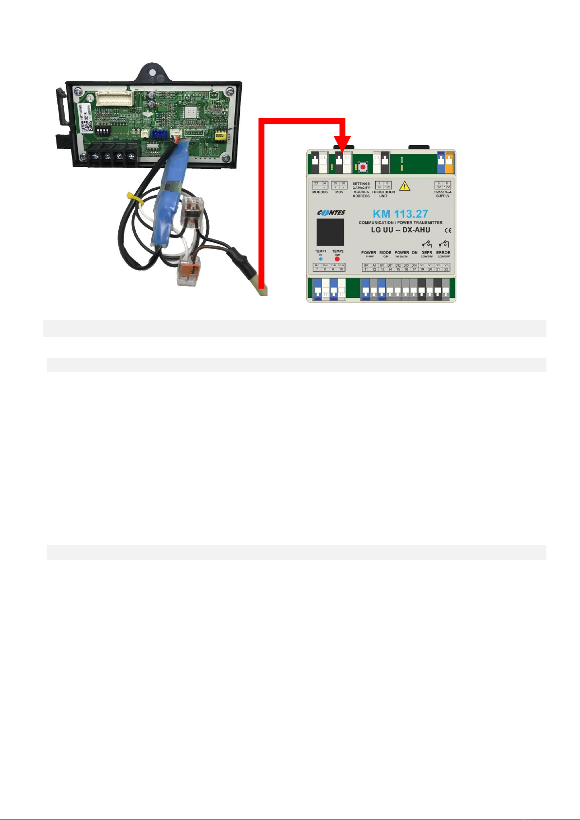
If the technical solution requires changing the evaporating/condensing pressure (temperature), it is
NECESSARY to use a combination of the KM113.27UU communication module with the MOV-UU power limitation
module and the corresponding compressor unit that allows this control.
When using MOV-UU, the algorithm of the compressor unit for changing the evaporating pressure/temperature
of approx. 14 to 6 °C (approx. 11 to 8 bar) is activated according to the setting of power code C1 to C7. In the
heat pump mode, according to the setting of power code H1 to H7, the algorithm of the compressor unit for
activating the condensing pressure/temperature of approx. 33 to 49 °C (approx. 19 to 29 bar) is activated.
Attention, this temperature is variable according to the specific installation conditions (the above values apply
to a pipe length of 7.5 m, elevation 0 m).

2020/07/23 page 6
Fig.1 –Application overview diagram KM113.27UU –COMPRESSOR UNIT UU** - HVAC –SYSTEM
I&C
Fig.2 - Complete terminal diagram KM113.27UU
Communication KM113.27UU-UU**
Communication KM113.27UU-MOV-UU
Power supply KM113.27UU-UU**
Module
MOV-UU
Outdoor unit UU**
APPLICATION OVERVIEW DIAGRAM
KM113.27UU-UU** - HVAC - I&C
Communication MODBUS I&C
Communication - I/O I&C
Air outlet
I&C system
for HVAC
Temperature sensors on
refrigerant piping
Air inlet
R410A / R32 refrigerant piping
HVAC unit
Outdoor unit
I&C
Power
supply
Te
m
p.
se
ns
or
IN
Te
m
p.
se
ns
or
O
U
T
P
O
W
E
R
co
nt
ro
l
0-
1
0
V
Fu
nc
ti
on
se
le
ct
Po
w
er
se
le
ct
St
ar
t
(O
N)
/
St
op
D
ef
ro
st
si
gn
ali
ng
Er
ro
r
si
gn
ali
ng
Supply

2020/07/23 page 7
4. INSTALLATION –CONNECTION TO THE AIR-CONDITIONING SYSTEM
4.1 MECHANICAL INSTALLATION
The communication box is to be installed near to the heat exchanger in
the HVAC system –refrigerant temperature sensors at the exchanger in
the HVAC system are connected to the module (standard cable length of
refrigerant temperature sensors on the evaporator is 3 m, sensors with a
length of 6 m - accessories on request).
The plastic box allows the module to be installed in indoor or outdoor
environments providing that safety installation procedures are observed
(the box integrity is not compromised; suitable cable glands are used). If
the box is installed outdoor, it is necessary to protect the box from direct
UV radiation (shaded area). In this case, we recommend using a box
with increased UV resistance (KM113.27UU-UV).
Preparation:
Remove the front cover from the installation box –loosen the 4 threaded
locks at the cover corners. Now you may access the connection terminals of the communication module and the
power supply source.
Have cable glands suitable for your intended application ready.
Attach the communication box to a suitable vertical plane (use the holes and covers at the rear of the box).
4.2 INSTALLATION –connection of refrigerant temperature sensors
Attach thermal sensors TEMP1 (blue)
and TEMP2 (red) to suitable locations on
the heat exchanger in the HVAC
system. The blue sensor is designed for
“input” of the refrigerant into the heat
exchanger, that is the small diameter
pipes, and the “red” sensor is designed
for “output” of the refrigerant from the
heat exchanger - large diameter pipes.
To properly attach sensors to Cu pipes
use, for example fastening clamps to
ensure proper heat transfer to the
sensor –see Fig.
After the sensors are attached make sure to insulate them thermally from the environment.
Description: 1 –the most sensitive spot of the sensor
2 –maximizes the contact between the sensor and the pipe

2020/07/23 page 8
Installation description:
Create a loop on the sensor cable in order to prevent collection of water/humidity in the sensor connection.
Notice:
Incorrect installation of temperature sensors may result in incorrect control of the cooling process.
Incorrect installation of temperature sensors may permanently damage the refrigerant sensors.
CONNECTION OF REFRIGERANT TEMPERATURE SENSORS TO KM113.27UU MODULE
Connect the temperature sensors TEMP1 and TEMP2 to the relevant terminals on the module. Observe color
coding of the sensors –blue sensor to “TEMP1 terminals - white wire to white terminal (No. 8), red sensor to
“TEMP2“ – white wire to white terminal (No. 10)!
Sensors are delivered with standard cable length of 3 m (sensors with longer cable length on request).
Notice:
When the temperature sensor is connected incorrectly or is defective the safety function of the communication
module is activated and the system generates corresponding error message (see the list of error messages of
the applied LG unit).
4.3 CONNECTION TO AN OUTDOOR COMPRESSOR UNIT –POWER SUPPLY,
COMMUNICATION
Connect a suitable power cable between the power terminals of the outdoor compressor unit (see the diagram
of the given unit) and the “supply” terminals in the communication box (terminal source “230 VAC” - “L, N”).
Connect suitable (shielded) communication cable between the outdoor compressor unit (see the diagram of the
used unit –usually terminals “N“ and “SIG“) and terminals “TO OUTDOOR UNIT” of the KM113.27UU (terminals
2+3).

2020/07/23 page 9
Fig.4 - Connection diagram of KM113.27UU to an outdoor compression unit (POWER SUPPLY +
COMMUNICATION)
4.4 Connection to an outdoor compression unit –power limitation module
The power limitation function (evaporative pressure-temperature / condensing
pressure-temperature change request) is only available for combinations of
KM113.27UU and a compressor unit that supports this function (see LG manufacturer's
specifications).
Make sure that the compressor unit is without voltage!
There is a risk of electric shock and damage to the device when installing the
module under voltage!
Install the MOV-UU power limitation module in the outdoor compressor unit - the module is connected to the
CN-CENTRAL connector on the PCB of the compressor unit.
Connect a suitable (shielded) communication cable between the MOV-UU terminals and the "MOV" terminals of
the KM113.27UU module (terminals 29 + 30).
COMMUNICATION (3), N (2)
POWER SUPPLY: L (1), N (2)

2020/07/23 page 10
Attention, it is necessary to observe the polarity/color of the terminals (e.g. white wire to the white terminal).
Fig.5 - Connection diagram of MOV-UU to an outdoor
compression unit UU-- and KM113.27UU
(e.g. for UU18W.UE4 unit)
5. CONNECTION TO SUPERIOR I&C HVAC SYSTEM
5.1 Control –descriptions, priorities
As for the external control the communication module allows you to use:
1/ “MODBUS“ communication protocol (only KM113.27UU)
2/ request on capacity through the use of 0…10V signal
3/ request on capacity through the use of contact inputs (3 max)
The communication module respects priority of external signals as follows:
If the MODBUS communication sends at least one record from the recorded registries only commands from
MODBUS will be respected (logic and analogue signals are ignored) until the power supply is turned off.
In the analogue signal is above the power output “1” the analogue input for the power value will be accepted as
the control input.
In the analogue signal is not active, the control through logic signals is respected (contacts).
MODBUS PROTOCOL CONTROL (MONITORING) (see separate section for description)
5.2 INPUTS FOR EXTERNAL CONTROL –digital, analogue
OPERATION ACTIVATION (ON-OFF)
Input terminals “ON” – Logic input (voltage-free contact).
When the contact "0V + D4" is closed (terminals 13 + 17) the operation of the device is allowed, when it is
opened the operation is stopped.
The current status of this input is indicated on the display by the size of the letter showing the selected
operational mode.
Example:
“cO … 24 … 24“ = operational mode “cooling “, operation is not allowed
“CO … 24 … 24“ = operational mode “cooling“, operation is allowed

2020/07/23 page 11
OPERATIONAL MODE REQUEST “COOLING=C“, “HEAT PUMP=H“
Input terminals “MODE C/H” - Logic input (voltage-free contact)
When the contact “0V+DI1“ is closed (terminals 13+14), the communication module sends a request to switch
the compressor unit from “cooling” mode to the “heat pump” mode = H“.
When the contact is off/open the communication module will send a request to switch the operational mode
from “heat pump” back to the “cooling mode = C“.
“POWER LEVEL REQUEST”
A request for power level may be executed through an analogue signal 0…10VDC or through 3 logic inputs
(voltage free contacts).
To directly influence the output (change of evaporating temperature in cooling mode/change of condensing
temperature in heat pump mode) it is necessary to install a capacity limitation module at the same time.
1. Input terminals “POWER 0…10V“
(terminals 11+12) –analogue signal
0…10V (0V = no request for power
level, 10V = maximum power level
request). The current power request is
shown on the right side of the display
module using 8 codes (“C0…C7“ or
rather “H0…H7“).
The power request algorithm requires at
least "C1"/"H1" code (i.e. at least 1.5V) to
activate the compressor unit.
The power request algorithm requires at
least "C0"/"H0" code (that means maximum
1.3V) to stop the compressor unit.
Fig.6 –Control diagram –Power request for analogue input
(Operational mode through logic input)
\
Power control
Level 1 to 7
Cool / Heat
Start / Stop
I&C

2020/07/23 page 12
2. Input terminals “POWER
1ST,2ST,3ST“ – logic inputs
(voltage free contacts):
no contact closed = no power
request
contact POWER 1ST closed
(terminals 13+15)=low power
request (displays shows C1/H1)
contact POWER 2ST closed
(terminals 13+16)=higher power
request (displays shows C4/H4)
both contacts POWER 1ST+2ST
closed (terminals 13+15+16) =
maximum power request (C7/H7)
The power request algorithm requires
at least "C1/H1" code to activate the
equipment (compressor unit).
The power request algorithm requires
at least "C0" / "H0" code to stop the
equipment (compressor unit).
Fig.7 –Logic input control diagram
5.3 OUTPUTS –INFORMATION ABOUT THE OPERATIONAL STATUS OF THE
EQUIPMENT
DEFROST
Logic output “DEFROST” (terminals 19+20).
The contact is closed if the equipment is in the “defrost” mode and at the same time the display module shows
an information message “d F”
The contact opens when the defrost mode is completed and when the refrigerant temperature in the heat
exchanger reaches at least 20°C.
During regular operational status the contact is off/open.
ERROR
Logic output “ERROR“(terminals 21+22).
The contact is off/open if the equipment diagnostics identified a defect or the equipment is not powered - no
supply voltage.
The defect code is also shown on the module display using the variable communicated by the MODBUS.
Defects identified by the communication module: Er .. 2 thermometer error “blue”
Er .. 6 thermometer error “red”
Er .. 99 Modbus communication error
Er .. 5 Communication error with the outdoor unit
Er .. XX outdoor unit errors
List of error codes of the outdoor unit –see the servicing manual of the applied LG equipment.
If more than one error has occurred at the same time, only the code of the first error is shown on the display.
During regular operational status the contact is on/closed.
Notice:
To restart the device after errors occur, it is NECESSARY to perform a "RESET" of the compressor unit device,
i.e.disconnect the device from the power supply.
Cool / Heat
Power level
0,1,4,7
Stop / Start
I&C

2020/07/23 page 13
5.4 CONTROL /COMMUNICATION MODBUS
In order to control up to 23 modules from the superior
system you may use the MODBUS communication as an
option to control or monitor the equipment.
Input/output “MODBUS“ (terminals 23+24)
The address for MODBUS communication is set using the
“SETTINGS” button. The setting procedure to be found in
paragraph 6.1.
MODBUS COMMUNICATION PARAMETERS
Serial line: 9.6 kbps, 8 bits, no parity, 1 stop bit
Station address: hex91 - hex9E (default hex91)
Supported functions - 3 (Multi_Read)
- 6 (Single_Write)
- 16 (Multi_Write)
Fig.8 –MODBUS communication wiring diagram for
controlling multiple modules
READING REGISTRIES
Name
Address
(decadically)
Properties/description
VERSION
4096
Software version
ERROR
4097
Errors according to the device’s self-diagnostics (see the service manual
of the LG device), (error 99 + Modbus communication error)
TEMP1
4098
Refrigerant input temperature to the exchanger +15 °C (blue sensor,
smaller diameter)
TEMP2
4099
Refrigerant output temperature to the exchanger +15 °C (red sensor,
bigger diameter)
DEFROST
4100
1 = active defrost mode of the outdoor unit
RECORDING REGISTRIES
Name
Address
(decadically)
Properties/description
POWER
4101
The value of the required power 0 to 7 corresponds with analogue input
FUNCTION
4102
Bit 0
0 = cooling; 1 = heating (heat pump)
Bit 1+2
Power value 0,1,2,3 (this value is used to control the power only if
the value in the registry is = 0)
Bit 3
0 = OFF; 1 = ON
Bit 6
1 = RESET
I&C

2020/07/23 page 14
POWER
7
6
5
4
3
2
1
0
A2
A1
A0
FUNCTION
7
6
5
4
3
2
1
0
RESET
OFF/ON
L1
L0
C/H
The RESET function is used for example when you need to transfer the control of hardware to signals without
the need to shut down the power supply to the unit.
When the communication is activated through the first record it is necessary to communicate more
often than during 1 minute.
(the recommended communication frequency is once every 1 to 10 second)
If writing is not repeated, the situation will be considered as a MODBUS communication error (error
Er 99).
Notice: If an error is active (ER--), the registers are automatically set to “0”.
Reading the values of the read registers is possible at any time without time limit and does not affect the
control by HW signals.
6. CONFIGURATION AND CONNECTION CHECK
6.1 Setting the power code and MODBUS communication address
Fig.9 –Adjustment mode activation diagram
The power code and address for external control (MODBUS)
are set using the “SETTINGS” button (CAPACITY +
MODBUS).
Setting procedure:
ENTERING THE “SETTINGS” MODE
1. Press the SETTINGS button while turning on the power to the
module
-Entering the setting mode is indicated on the display by a
character
ENTERING THE “POWER CODE SETTING” MODE
2. Hold the SETTINGS button for 5 s.
-The display shows the set power code in kW.
-The power code can be changed by shortly pressing the SETTINGS button. It changes cyclically
according to the following table

2020/07/23 page 15
Cooling
power
kW
1.5
2
2.6
3.5
4.5
5
6
7
Btu
05
07
09
12
15
18
21
24
kW
8
10
12
14
16
19
23
28
Btu
30
36
42
48
60
70
85
90
ENTERING THE “MODBUS ADDRESS SETTING” MODE
3. Hold the SETTINGS button for 5 s.
-The display shows the set address for MODBUS communication. This address is also usable for LG
central control systems.
The MODBUS address can be changed by briefly pressing the SETTINGS button. It changes
cyclically from 90 to A7. (90 = service communication; 91,…, A7 = MODBUS communication)
Address
90
91
92
93
94
95
96
97
99
9A
9B
9C
9D
9E
9F
A0
A1
A2
A3
A4
A5
A6
A7
4. Hold the SETTINGS button for 5 s to return to point 2.
If you do not press the SETTINGS button for 10 seconds, the last set value is automatically saved, the setting
mode is exited and the initial information sequence appears on the display.
Attention! After changing the settings, it is necessary to restart the outdoor unit (restore power). If
the outdoor compressor unit is not restarted, the changes are not accepted by the unit.
6.2 INTRODUCTORY INFORMATION SEQUENCE
Turn on the power supply –the display will show the introductory sequence:
1st cycle - basic hardware and software setting information –example:
“LG –UU –16 –So –4.4 “
Explanation –module designed to communicate with LG compressor unit, model series UU, pre-set cooling
power 16 kW (outdoor unit UUD1, UUD3, UU60W, UU61W), software version 4.4
2nd cycle - basic hardware and software setting information –example:
“LG –UU –16 –So –4.4 “
Explanation –module designed to communicate with LG compressor unit, model series UU, pre-set cooling
power 16 kW (outdoor unit UUD1, UUD3, UU60W, UU61W), software version 4.4.
After these introductory sequences the display will show the current status of the requests - example
“C0 - 18 - 22“
Explanation: operational cooling mode, no power request, current temperature of the refrigerant pipes at the
input to the heat exchanger in the HVAC system –18 °C (blue sensor), output temperature 22 °C (red sensor).
refrigerant temperature display range MIN = -9, MAX= 99.
Notice:
If the introductory sequence does not correspond with your installation (the power code does not match the
connected outdoor unit), set the corresponding sequence following the procedure described in the item 4.4
above.
6.3 INSPECTION OF INPUTS / OUTPUTS –TESTS
WARNING! All the described functionality tests may ONLY be done by an authorized person. Incorrect test
performance may result in equipment breakdown. Make sure that the test will not damage the equipment or
endanger persons near the equipment!

2020/07/23 page 16
INPUT TESTS
1. Test for the presence of the refrigerant temperature sensor at the input to the heat exchanger (terminals
TEMP1, blue) - if the sensor is defective or the connection is incorrect, “Er-02” error flashes on the LED
display. If the sensor is connected correctly that is the white wire is connected to the white terminal, the
relevant LED illuminates (left, blue underneath the displays on the PCB).
2. Test for the presence of the refrigerant temperature sensor at the output from the heat exchanger
(terminals TEMP2, red) - if the sensor is defective or the connection is incorrect, “Er-06” error flashes on
the LED display. If the sensor is connected correctly that is the white wire is connected to the white
terminal, the relevant LED illuminates (right, red underneath the displays on the PCB).
Both thermometers are the same and therefore exchangeable in terms of the functionality. Color coding is
only used to identify the purpose and use.
3. An analogue input test is carried out by applying DC voltage of 0-10V to the "POWER 0..10V" terminals. The
display shows C0, C1 ... C7. Because we need 7 positions for the 0-10V range, the voltage change by 1
level corresponds to 1.4V (approximately).
4. Test of the logic (contact) input for power switching - disconnect the analogue voltage and test the logic
inputs. Use a suitable conductor and gradually connect the "POWER 1ST / 2ST / 3ST" terminals. When
connecting the "0V" (No.13) terminals with the "DI2” (No.15) terminal, the power level 1 is activated - the
display shows C1. When connecting the "0V" (No.13) terminals with the "DI3” (No. 16) terminal, the power
level 2 is activated - the display shows C4. When connecting the "0V” (No.13) terminals with the "DI2”
(No.15) and at the same time the “D13” (No. 16) terminal, the power level 3 is activated - the display
shows C7.
5. Test of the logic (contact) input for operating mode switching - disconnect all power requirements and
connect the "MODE C / H" terminals using a suitable conductor. When connecting the "0V” (No. 13)
terminals with the "DI1” (No. 14) terminal, the heat pump mode is activated - the display shows “H0”. Now
connect the power request - the corresponding request ("H1" ...) appears on the display.
OUTPUTS TESTS
6. Fault /error message test - for example, if you disconnect the TEMP1 temperature sensor, an error occurs
and it is shown on the display “Er-02 - Er-02 - Er-02……”, and the output ERROR opens the contact (No.
21+22).
7. Test of the DEFROST output function starts when the power supply is connected. The DEFROST output
(No.19 + 20) closes for approximately 1s.
Notice: This output is necessary for correct operation of the “HVAC-compressor unit" working in the "heat
pump" mode. The superior HVAC control system must ensure the appropriate response of the HVAC
system.
After testing, check the tightness of bushings and reinstall the cover of the installation box and inspect visually
for tightness.
6.4 Inspection of settings during operation
During operation, without deactivating the supply voltage, the set power code, the address for central control
(MODBUS) and the last 10 device error states can be verified.
1. Hold the SETTINGS button for approx. 5 s.
The display shows the set power code in kW.
2. Hold the SETTINGS button for approx. 5 s.
The display shows the set address for MODBUS communication. This address is usable (same) for LG
central control systems.

2020/07/23 page 17
Warranty card
Equipment specifications
Product
communication box to control outdoor compressor
condensation unit LG Electronics.
model series “UU**„
Model
KM113.27UU
Scope of delivery –accessories
Communication module
Power supply (12VDC), switch,
Refrigerant temperature sensor “BLUE” (TEMP1)
Refrigerant temperature sensor “Red” (TEMP2)
Installation box, auxiliary terminals,
Cable glands (6pcs),
Installation manual
Serial number
Date of sale
Seller
Installation date
Installation performed by
The manufacturer provides a 24-month warranty covering the quality of the product starting on the day of sale. The warranty
covers defects of the purchased product,which appear during the warranty period. In order to keep your warranty valid the
installation must be performed by an authorized person and the “Warranty form” must be properly filled out. The client shall
always claim the given warranty rights at his own seller.
Service contacts
Manufacturer (branch)
CONTES, spol. s r.o.
Mikuleckého 1314
147 00, Praha 4
Telephone
261 710 655
Distributor
Jílovišťská 691
155 31, Praha 5
244 402 140
info@ran-klima.cz
Seller’s service
Table of contents
Other LG Inverter manuals

LG
LG LG N1C-V5 Series User manual

LG
LG LG A1C-A5 Series User manual

LG
LG N2W-L5 Series User manual

LG
LG LG N1C(W)-L5 Series User manual

LG
LG MonoX ACe Assembly instructions

LG
LG LG340N1C-A5 User manual

LG
LG Mono X Plus Series User manual

LG
LG LG S1C-G3 Series User manual

LG
LG LGES-5048 User manual

LG
LG LGXXXN2W-L5 User manual
Popular Inverter manuals by other brands

Lenze
Lenze i510-Cabinet manual

AEG
AEG Si 150 Operation and safety notes

SamplexPower
SamplexPower PST-600-12 owner's manual

Maywah Energy
Maywah Energy MaySun-1200W-B manual

Orbit
Orbit AC/DC-1200 Series User's guide and technical reference manual

Xantrex
Xantrex Prosine PS2.5 and Installation and operation guide